Keywords
|
| Atomiser, BMS/FSSS, LDO, HFO, Van diffuser, Firing, Furnace, Angle, Mixing. |
INTRODUCTION
|
| Air cooled oil gun is used to fire oil in furnace .we are using three types of oil gun .they are Pressurized type, Concentric type and Parallel type. Mostly parallel type oil gun is preferred than others. Firing, firing angle and atomising style is common for both parallel and concentric type, but steam and oil flow piping arrangement is different. Repairing of concentric oil gun is not very easy job, whereas in parallel type it is very easy.pressurised oil gun is old model. It was used before the development of parallel and concentric type. In this type we have to pressurize the oil upto approximately 25 kg/cm2 and also we can not get desired firing angle. |
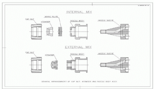
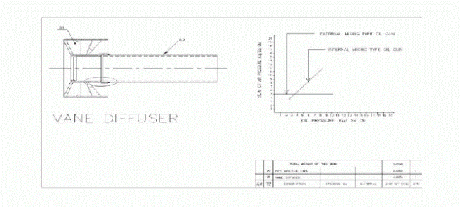
| Two types of mixing are being used in both concentric and parallel type oil gun .They are internal and external mixing. Generally external type is recommended to use .because we have to maintain differential pressure (DP) between oil and steam in internal type and steam pressure should be 1.5Kg/cm2 higher than oil pressure. Whereas in parallel type steam pressure must be 5 kg/cm2 (fixed) and we can vary oil pressure upto requirement. Firing angle can be changed by changing atomiser of oil gun. Van diffuser is used for flame stabilization. Flame diameter and length can be adjusted by van diffuser. |
 |
DESCRIPTION
|
| Combustion is rapid combination of oxygen with fuel. The oxygen comes from air which contains about 21% by volume. The basic requirements for the efficient combustion of fuel oil is that it should be “Atomized” in to fine particles or droplets for easy ignition and effectively mixed with correct quantity of oxygen in the air. Mixing and burning exactly the right amount of fuel oil and oxygen so that nothing is left over attains perfect combustion. Good combustion requires a proper fuel and air mixture and an initial and sustained ignition source. For effective atomization it is essential that the fuel oil viscosity is low enough for the fuel oil to be divided in to finer particles for effective mixing with oxygen in the air. |
| Atomiser is capable of firing Light Fuel Oil (LFO) with compressed air atomization and Heavy Fuel Oil (HFO) with steam atomisation. The air-cooled design is robust, simple and replaces successfully the cumbersome Auto Retract mechanism. The oil guns can be left always in the firing position and the cooling air provided protects the atomiser parts from overheating. |
THE OIL GUN ASSEMBLY
|
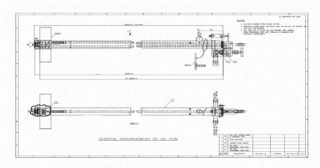
| The complete oil gun assembly consists of two major sub-assemblies the stationary part and removable part. |
| The stationary part is made up of |
| a) Guide Pipe & Diffuser Assembly. |
| b) Stationary union assembly and connecting tube. |
| The stationary part is bolted on to the Wind box by means of mounting plates or flange. The entire assembly can be removed from the Wind box compartment after the removal of the mounting plate bolts. |
| NOTE: when removing or inserting the assembly, a steel rod or capped pipe should be inserted in the guide pipe to ensure alignment of the seal tube and diffuser with the wind box nozzles. |
| The guide pipe assembly is welded to the mounting flange. The diffuser is attached to the guide pipe by two links and pivoting extension lever (the burner tilt linkages). A flexible metal seal tube is welded onto the diffuser at the front. The back end of the flexible seal tube slides inside the guide pipe over a short distance. This arrangement adapts the oil gun to the tilting feature of the windbox nozzles. |
 |
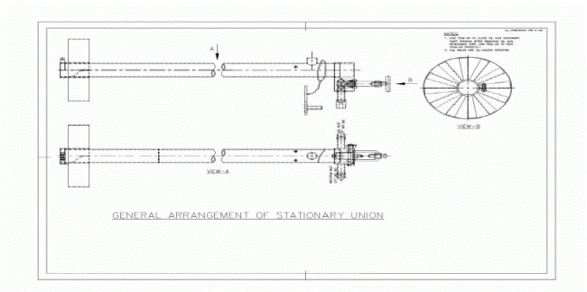
| The stationary union is welded to a tube called connecting tube. The stationary union provides connection for admission of oil and atomising agent and at the same time couples the removable part. The gun engagement limit switch is actuated by the actuator lever when the oil gun removable part is engaged onto the stationary part and coupled. The limit switch contacts serve to indicate the control system that the oil gun is engaged in position and is ready for firing. |
| The connecting tube with stationary union is inserted into the guide pipe and welded to it to maintain the specified distance from the diffuser plane. |
| The removable part of the gun consists of the removable union, two parallel oil gun pipes with flexible portion and nozzle assembly. The purpose of the parallel arrangement of the oil gun pipes is to separate fuel and atomising agent till the mixing point in the atomiser and to minimize temperature effect of one medium on the other. The length of the removable oil gun pipes (Dimension K or KF) is predetermined to ensure proper location of the atomiser with respect to the diffuser. |
| NOTE: The oil gun tip Vs diffuser relationship should be checked on all guns prior to initial operation. |
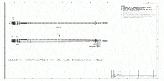 |
| Guides on the outer oil gun pipe maintain the concentric position of the oil gun with respect to stationary part. The flexible tubing adapts the gun to vertical tilting of the wind box nozzle and serves to absorb the differences in expansion between the pipes. |
| While replacing damaged flexible hose take Utmost care to avoid weld slag inclusions and to maintain the accurate K or KF dimensions. |
 |
| The atomising nozzle assembly consists of Spray Plate (Atomiser), which is secured to the nozzle body by means of a cap nut. The atomising agent (Compressed air / Steam) enters the oil gun through the lower part of the stationary union and the oil enters the upper part. They are carried separately through the entire length of the gun by means of two parallel oil gun pipes. |
| Oil is admitted to outer holes in the spray through the outer row of the holes in the nozzle body. The Atomising agent (compressed air / Steam) passes through the inner holes of the Nozzle body. Oil pass through the outer holes of the spray plate and mixes with the atomising agent which passes through the inner radial holes of spray plate. In this process oil gets atomised.Atomised oil is discharged in to the furnace in the form of a spray. Spray angle can be changed by using different spray plates. |
COOLING AIR ARRANGEMENT
|
| The cap nut that holds the atomiser part in the oil gun nozzle body has been provided with holes. The air that flows through the holes remove the heat effectively and keep the atomiser parts cool. The cooling air admission stub is arranged on the connecting tube, near the stationary union. |
| The cooling air flows through the connecting tube, guide pipe, flexible seal tube and escapes into the furnace through the holes in the cap nut. The diffuser hup has been carefully dimensioned to direct the cooling air fully through the holes of the cap nut. The cooling air is tapped from scanner / oil gun cooling fan and an independent ducting system distributes the air to individual oil guns. |
OPERATION
|
| 1. Oil gun operation is controlled by the BMS/FSSS, which provides for proper operating sequences (gun engagement, valve opening and closing etc), monitors operating conditions (pressures, flow, gun and valves positions, etc.,) and provides for automatic shutdown upon unsatisfactory conditions. |
| 2. Regardless of above and supplementary to any features provided by a control system, the following basic rules always apply. |
| i. Prior To Initial Firing |
| a. Purge the furnace for at least five minutes. |
| b. Check fan and damper regulating equipment manually for proper operation through the entire range. |
| ii. Make sure that ignitors adjacent to the oil guns to be lit off are operating properly. Always use an ignitor to ignite oil gun. Never attempt to light off one oil gun from another gun in service. |
| iii. Use proper setting of the secondary air dampers. The secondary air from the wind box is distributed over the auxiliary air and oil compartment by means of individual dampers. Equally important to the distribution of air is the total amount of air. The best determination of the proper amount of air is by means of flue gas analysis through Orsat measurements. |
| iv. Before inserting an oil gun, inspect the gun for the correct tip for the type of atomization selected and for proper assembly of nozzle plates. Make sure that the stationary union gaskets are in place. When lighting off a gun, make sure (by visual observation) ignition takes place immediately after opening the oil supply valve. If ignition does not take place or is very unstable, shut off the oil and remove the gun after scavenging. Do not attempt to relight same gun until the cause of non-ignition has been detected and corrected. |
| v. When burning heavy fuel of oil, temperature of oil should be high enough to keep the oil viscosity between 90- 130 SSU (15-20 centistokes). Refer viscosity chart of the Fuel oil used to determine the temperature of oil. Prior to placing heavy oil guns in service, the oil should be recirculated for preheating. Make sure that the recirculation valves are closed / partially throttled before placing the first oil gun in service. |
| vi. When putting an oil gun in service, always admit the atomizing agent (compressed air / steam) to the gun before the oil. |
| vii. After removing an oil gun from service, scavenge the gun through both sides. After scavenging, close all the valves. Do not leave idle guns inserted without cooling air, when there is fire in the furnace. |
| NOTE: Before scavenging an oil gun place the adjacent ignitor in Service. If the adjacent ignitor is not available, do not scavenge the gun, but remove the gun from the pipe and clean it manual. |
 |
PRE-COMMISSIONING CHECKS
|
| 1. All the oil guns shall measure K ± or KF ± 3mm exactly; Inspect; correct and / or report. |
| 2. Inspect and correct, if necessary, the B-dimension of the set up tool for ïÃâñ1mm tolerance. Set up tool is simply a long pipe with dummied removable union and handle. Dimension-B is the length of the pipe portion. The face of the pipe free end corresponds to the cap nut face of the oil gun. Dimensions B equals to KF + 46.5mm for Air Cooled Oil Guns. |
| 3. Check for any damages to the flexible seal tube assembly and oil gun assembly hoses. |
| 4. Ensure that the limit switch position has been properly aligned for correct actuation when oil gun removable part is engaged. |
| 5. Check for any damages to the limit switch. |
| 6. Before mounting the oil gun stationary part with wind box, engage the set up tool into the stationary union along with copper clad asbestos gaskets. Inspect for correct disposition of the set up tool face with respect to the diffuser hub for required tolerance; correct it, if required, by breaking the shop weld between connecting tube and guide pipe (Refer to assembly drawing). |
| 7. After mounting the oil gun stationary part with wind box, inspect for correct disposition of diffuser with respect to the wind box nozzle outlet plane. Correct it, if required, by breaking the shop weld between the guide pipe flange and guide pipe. (Refer to assembly drawing). |
| 8. Ensure that the atomiser nozzles of correct designation, as written down in the technical data section and assembly drawing, have been supplied. |
| 9. See that the oil and atomising air connection hoses are connected to the appropriate ports at the stationary union. Plug the unused ports by welding. |
| 10. Take care to lay the oil, atomising air / steam connection hoses in freely hanging U-shape without any sharp bend near the end fittings. |
| 11. After cooling air connections are made to all oil guns and with all oil guns mounted in position, measure the cooling air pressure at the tapping provided on the connecting pipe, with FD & ID fans running at 30% load. It shall measure not less than 20mm wc, approximately. |
| 12. Ensure that the end caps are available to close the stationary union opening when oil guns are removed for maintenance and end caps shall be properly tied to the individual oil gun stationary part. |
TROUBLE SHOOTING
|
| IF ATOMIZATION IS POOR |
| 1) ATOMISER NOZZLES ARE BLOCKED INTERNALLY |
| a. Before commissioning, steam blow / purge oil and atomising air / steam lines. |
| b. Remove pipe scale, welding slag and sand used for pipe bending etc., from oil and air / steam holes / slot / passages. |
| c. Use compressed air / steam to clear any debris. |
| d. Remove any inside carbonized deposits. |
| e. Remove carbon growth on atomizer, face or cap nut. |
| f. Use paraffin or kerosene or both to wash away heavy oil films or loose carbon deposit. |
| g. Use soft metal scrapper to remove heavy carbon deposits. |
| h. Do not use hardened scrapper which will spoil metal to metal sealing surfaces. |
| i. Do not use abrasive blast equipment or muffle furnace for cleaning atomizer parts. |
| 2) BADLY WORN ATOMISER |
| a. Check nozzle holes sizes using go and no go pin gauges. The no go pin is normally 101.5% of top limit for the particular nozzle. |
| b. The atomiser face should be square and flat. If not, correct the same by lapping with fine carborundum paste. |
| III. ATOMISER PARTS BADLY DAMAGED |
| a. Damaged while hammering out of cap nut. Atomiser components should be handled gently. It shall not be manhandled. |
| b. Dropped onto floor producing dents on sealing face. |
| c. Damaged while cleaning with unsatisfactory tools. |
| d. Sealing face lapped on a convex or concave instead of flat lapping plate. |
| e. Atomiser worn by clearing on unapproved blast cleaning equipment. |
| f. Surface hardness affected by use of muffle furnace to clean off surface carbon. |
| g. Sealing face of oil gun / sprayer end left exposed to damage. |
| h. Gun end lapped convex by inexperienced fitter. |
| i. Cap nut of oil gun damaged while removing jammed atomiser. |
| j. Cleaning cap nut with unsatisfactory tools. |
| k. It is false economy to use damaged atomiser parts. |
| IV. IMPROPER ASSEMBLY OF ATOMISER PARTS |
| a) Oil leakage from cap nut due to |
| • Cap nut not tightened; |
| • Dirt between metal to metal seal surface; |
| • Assembly of damage atomiser parts / cap nut / gun end. |
| b) Carbon growths on atomiser face and cap nut. Further worsening of atomisation due to oil spray impinging on carbon growths on cap nut resulting in large oil droplets or streams of oil – Dripping of oil from atomiser. |
| c) Atomiser is not sealed satisfactorily against oil gun / sprayer and, allowing air cross flow and restricting fuel oil flow. |
| d) To disassemble the oil gun easily without damage to atomiser parts such as Back plate, Spray plate and Gun follow the procedure below. Hold the Gun rigidly across the flats adjacent to the cap nut, Loosen cap nut and undo 1 or 2 turns. Using a piece of wood or soft metal, tap the atomiser back into the nut. This procedure keeps the spray plate / atomiser square with the cap nut and prevent wedging. Care must be taken not to drop the atomiser parts when the cap nut finally clears the oil gun. |
| e) The cap nut should be tightened properly with the recommended torque value. (20 to 30 kg-m) |
MAINTENANCE
|
| a) The threaded portion of the atomizer body should be covered with a non- hardening high temperature lubricating compound. This facilitates subsequent removal. Particular care must however, be taken to ensure that no compound is trapped between the sealing faces. |
| b) Lapped atomiser parts must be kept in a plastic or a similar container to prevent damage or scratching of sealing face. |
PURGING OF OIL GUN ATOMISER
|
| a) Purge the gun for 5 to 10 minutes before withdrawal for maintenance. |
| b) Incomplete purging of oil gun will result in carbonization of oil in the gun. Any fuel oil left in the gun, if inadequately cooled, will carbonise due to overheating by furnace radiation. |
PROPER PARAMETERS ATOMISING OF AIR / STEAM
|
| a) A variable atomising air / steam, pressure of 1.50Kg/sq.cm (g) above oil pressure is required for internally mixing type atomiser. Atomising air / steam pressure of 5Kg/sq.cm (g) is required for external mixing type atomiser. |
| b) The atomising air / steam shall not contain condensate; shall be atleast dry and free of condensate for proper burning of fuel. |
CONCLUSION
|
| The purging of oil gun is done at two times only. When Oil gun is withdrawn from firing, Scavenge is started automatically by Logic (300 Sec) and while removing an oil gun from guide pipe for manual cleaning or some times. Scavenge is initiated by local scavenge pushbutton. An oil gun is not in firing mode i.e., during coal firing (load condition), we may scavenge oil gun for 30 Sec at every 30 minutes. Because during coal firing the unburned coal, ash and other particles will be deposited on surface of atomiser .Slowly this will choke atomiser holes completely. So oil gun can not be taken immediately into service at heat demanding time. In order to avoid choking problem we may scavenge oil gun at coal firing time. The above mentioned scavenging is not yet suggested by anyone. Further the BMS logic to be modified accordingly to attain this modification without affecting the boiler operation. |
References
|
- Chattopadhyay.2012, Boiler Operation Engineering (Q&A)
- BHEL, Boiler and Auxiliaries.
- Boiler Controls (P) Ltd, 2010 Operation and Maintenance Manual for Fuel Firing System
- Basu, Kefa, Jestin, Boiler and Burners
- Karnatz mass – Dibble, Combustion
- Oil gun and Gas firing Equipment from Alstom-www. global spec.com
- Oil gun and Gas firing Equipment- www.apcompower.com
|