Keywords
|
| Alert module; AT89S51; Biometrics; GSM module; Iris recognition; SIM card; Voice annunciation module. |
INTRODUCTION
|
| ATMs have become very popular with the general public for their availability and general user friendliness. ATMs are now found in many locations. For example, ATMs are typically found in restaurants, supermarkets, Convenience stores, malls, schools, gas stations, hotels, work locations, banking centers, airports, entertainment establishments, transportation facilities ATMs are typically available to consumers on a continuous basis such that consumers have the ability to carry out their ATM financial transactions and/or banking functions at any time of the day and on any day of the week. |
| In real time ATM cards are being used as a form of identification and authentication. But there is a highest possibility for the ATM cards to be theft or lost and even if the card is bent or heated, it becomes useless to access the ATM machine. With the increase of automated teller machine (ATM) frauds, new authentication mechanisms are developed to overcome security problems. One inherent problem with ATM cards is the possibility of loss or theft and it should be carried for each and every transaction, which we forget to do in many cases. |
| This problem has promoted interest in biometric identification methods, including iris recognition. The iris is chosen due to its unique biological properties, exceptionally suited for identification. It is protected from the environment, stable over time, unique in shape and contains a high amount of discriminating information. |
| This Proposed paper uses IRIS recognition system which is a computer application for automatically identifying or verifying a person by an image of the IRIS from the IRIS scanner fitted with the ATM machine, operated using our SIM in the mobile phone. Thus this paper proposes a method to integrate iris recognition in ATM with SIM instead of ATM cards to develop a high security access environment. |
HARDWARE DESCRIPTION
|
| A. Power Supply |
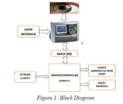
| The power supply circuit is built using filters, rectifiers, and then voltage regulators. The input is a 230V AC supply, which is converted into a DC voltage when it passes through the rectifier circuit. The output of the rectifier circuit is an unregulated DC voltage, through the regulator circuit (LM7805). Hence the final output obtained from the power supply circuit is +5V DC supply. |
| B. Microcontroller |
| A microcontroller is heart of the embedded system. It contains a processor core, memory, and programmable input/output peripherals. The microcontroller used here is AT89S51 from ‘ATMEL’ with 4K Bytes of In-System Programmable (ISP) Flash Memory, 128 x 8-bit Internal RAM and 4.0V to 5.5V Operating Range . The image that is obtained from the iris scanner is fed into the microcontroller such that the input image of the iris is matched with the image that is already stored in the database. |
| C. Alarm Unit |
| A buzzer or beeper is a signaling device; it is usually electronic and is typically used in automobiles, household appliances such as a microwave oven, or game shows etc. Initially this device was based on an electromechanical system which was identical to an electric bell without the metal gong (which makes the ringing noise).The alarm is activated when there is a wrong person accessing the account. The wrong client access can be found when the SIM number and the IRIS image do not match with that of the previously stored information in the database. |
| D. GSM Modem |
| A GSM modem is a wireless modem that works with a GSM wireless network. A wireless modem behaves like a dial-up modem. The main difference between them is that a dial-up modem sends and receives data through a fixed telephone line while a wireless modem sends and receives data through radio waves. A GSM modem can be an external device; it contains a SIM scanning device. Typically, an external GSM modem is connected to a computer through a serial cable or a USB cable. Computer can operate the GSM modem using AT commands, through which a message can be sent as well as received. GSM modems support an extended set of AT commands. |
| E. Voice Annunciation Unit |
| The voice annunciation unit is connected with one of the ports in the microcontroller. Eight different voices can be enabled using this voice chip. Each process is intimated using voice annunciation unit. |
| F. Serial Communication |
| Serial communication is the process of sending data one bit at a time, sequentially, over a communication channel or computer bus. Here serial communication between the computer and the microcontroller takes place through max232 IC. The MAX232 is an integrated circuit that converts signals from an RS-232 serial port to signals suitable for use in TTL compatible digital logic circuits. |
SIM CARD RECOGNITION
|
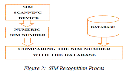
| One of the key features of GSM is the Subscriber Identity Module, commonly known as a SIM card. A subscriber identity module or subscriber identification module (SIM) is an integrated circuit that securely stores the International Mobile Subscriber Identity (IMSI) and the related key used to identify and authenticate subscribers on mobile telephony devices (such as mobile phones and computers).SIM cards are identified on their individual operator networks by a unique IMSI. The SIM is inserted in the GSM Module; the SIM scanning device in the GSM Module scan’s the SIM and retrieves the SIM number from it. This retrieved SIM number is compared with the previously stored SIM number in the database. If the SIM number matches with that of the database, then further process of scanning and recognizing the iris of the authenticated person takes place |
IRIS RECOGNITION SYSTEM
|
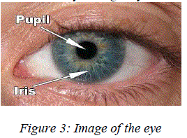
| The iris is the colored portion of the eye that surrounds the pupil as shown in Fig. 3. It controls light levels inside the eye similar to the aperture of a camera. The round opening in the center of the iris is called the pupil. The iris is embedded with tiny muscles that dilate and constrict the pupil size. It is full of richly textured patterns that are distinct from person to person, and in fact are distinct from left eye to right eye of the same person. |
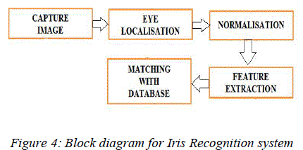
| Generally, an iris recognition system is composed of many stages as shown in Fig. 4. Firstly, an image of the person's eye is captured and preprocessed. Secondly, the image is localized to determine the iris boundaries. Thirdly, the iris boundary coordinates are converted to the stretched polar coordinates to normalize the scale and illumination of the iris in the image. Fourthly, features representing the iris patterns are extracted based on texture analysis. Finally, the person is identified by comparing his/her features with an iris feature database. |
A. Image Acquisition
|
| The iris image should be rich in iris texture as the feature extraction stage depends upon the image quality. The following attentions have been taken care at the time of grabbing the image. |
| • High resolution and good sharpness: It is necessary for the accurate detection of outer and inner circle boundaries. |
| • Good lighting condition: The system of diffused light is used to prevent spotlight effect. |
| B. Iris Localization |
| The acquired iris image has to be preprocessed to detect the iris, which is an annular portion between the pupil (inner boundary) and the sclera (outer boundary). The first step in iris localization is to detect pupil which is the black circular part surrounded by iris tissues. The center of pupil can be used to detect the outer radius of iris patterns. The important steps involved are: |
| (a) Pupil detection |
| (b) Outer iris localization |
| (a) Pupil Detection |
| The iris image is converted into gray scale to remove the effect of illumination. As pupil is the largest black area in the intensity image, its edges can be detected easily from the binarized image by using suitable threshold on the intensity image. But the problem of binarization arises in case of persons having dark iris. Thus the localization of pupil fails in such cases. In order to overcome these problems Circular Hough Transformation for pupil detection can be used. The basic idea of this technique is to find curves that can be parameterized like straight lines, polynomials, circles, etc., in a suitable parameter space. The transformation is able to overcome artifacts such as shadows and noise. |
| The procedure first finds the intensity image gradient at all the locations in the given image by convolving with the sobel filters. The gradient images (Gvertical and GHorizontal) along x and y direction, is obtained by kernels that detect horizontal and vertical changes in the image. The sobel filter kernels are |
 (1) (1) |
| The absolute value of the gradient images along the vertical and horizontal direction is obtained to form an absolute gradient image using the equation |
 (2) (2) |
| Where Vertical is the convolution of image with Cvertical and Ghorizontal is the convolution of image with Chorizontal. The absolute gradient image is used to find edges using Canny [7]. The edge image is scanned for pixel (P) having true value and the center is determined with the help of the following equations |
 (3) (3) |
| Where x, y is the coordinates at pixel P and r is the possible range of radius values, θ ranges from [0: π] For a particular value of r, the values of xc and yc are obtained and stored in an accumlator and the accumulator counter is incremented every time the values of xc and yc satisfy image dimension criteria. The maximum value of accumulator counter gives the centre of the pupil along with the radius as shown in Figure 5. |
| (b) Outer Iris Localization |
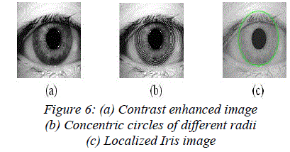
| External noise is removed by blurring the intensity image. But too much blurring may dilate the boundaries of the edge or may make it difficult to detect the outer iris boundary, separating the eyeball and sclera. After filtering, the contrast of image is enhanced to have sharp variation at image boundaries using histogram equalization as shown in Figure 6(a). This contrast enhanced image is used for finding the outer iris boundary by drawing concentric circles, as shown in Figure 6(b), of different radii from the pupil center and the intensities lying over the perimeter of the circle are summed up. Among the candidate iris circles, the circle having a maximum change in intensity with respect to the previous drawn circle is the iris outer boundary. Figure 6(c) shows an example of localized iris image. |
| C. Iris Normalization |
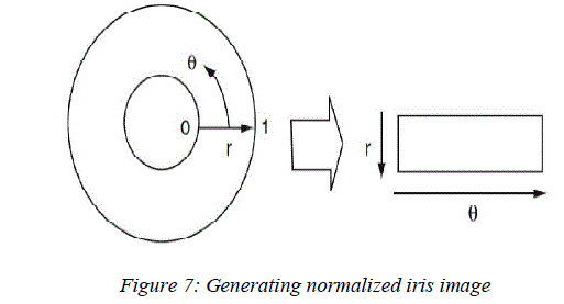
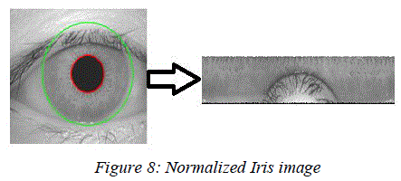
| Once the iris region is segmented, the next stage is to normalize this part, to enable generation of the "iriscode" and their comparisons. Since variations in the eye, like optical size of the iris, position of pupil in the iris, and the iris orientation change person to person, it is required to normalize the iris image so that the representation is common to all with similar dimensions. Normalization process involves unwrapping the iris and converting it into its polar equivalent as shown in Fig. 7 |
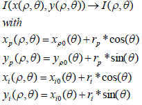
| The remapping of the iris region from the Cartesian coordinates to the normalized non-concentric polar representation is modeled as: |
 (4) (4) |
| Where rp and ri are respectively the radius of pupil and the iris, while (xp (θ), yp (θ)) and (xi (θ), yi (θ)) are the coordinates of the pupillary and limbic boundaries in the direction θ. The value of θ belongs to [0; 2?], ρ belongs to [0; 1]. |
| D. Feature extraction |
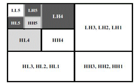
| The Wavelet transform is used to extract features from the enhanced iris images. Haar wavelet is used as the mother wavelet. The Wavelet transform breaks an image down into four sub-sampled images. The results consist of one image that has been high-pass filtered in the horizontal and vertical directions (HH or diagonal coefficients), one that has been low-pass filtered in the vertical and high-pass filtered in the horizontal (LH or horizontal coefficients), one that has been lowpass filtered in the horizontal and high-pass filtered in the vertical (HL or vertical coefficients), and one that has been low-pass filtered in both directions (LL or details coefficient). |
| In order to generate the binary data, feature vector is encoded by using two and four level quantization as shown in Fig. 7, which shows the process used for obtaining the feature vectors with the optimized dimension. Here, H and L refer to the high-pass and the low-pass filter, respectively, and HH indicates that the high-pass filter is applied to the signals of both axes. |
| E. Identification |
| The last module of an iris recognition system is used for matching two iris templates. Its purpose is to measure how similar or different the templates are and to decide whether they belong to the same individual or not. An appropriate match metric can be based on direct point-wise comparisons between the phase codes. The test of matching is implemented by the XOR operator that is applied to the encoded feature vector of any two iris patterns. The XOR operator detects disagreement between any corresponding pair of bits. The system quantifies this matter by computing the percentage of mismatched bits between a pair of iris representations, i.e., the normalized Hamming distance. Let X and Y are two iris templates to be compared and N is the total number of bits so, HD is equal to the number of disagreed bits divided by N as shown in equation 5. |
 |
| In order to avoid rotation inconsistencies which occur due to head tilts, the iris template is shifted right and left by 8 bits. It may be easily shown that scrolling the template in polar coordinates is equivalent to iris rotation in Cartesian coordinates. The system performs matching of two templates several times while shifting one of them to four different locations. The smallest HD value amongst all these values is selected, which gives the matching decision. |
| • If HD <= 0.32 decide that it is same person |
| • If HD > 0.32 decide that it is different person |
OVERALL FLOWCHART OF THE PROJECT
|
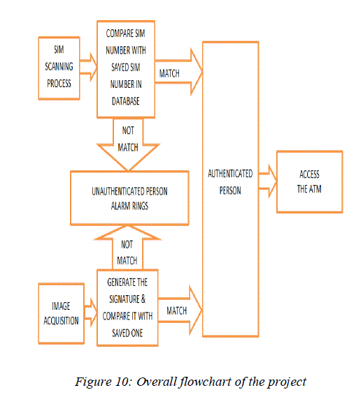
| The first step is to insert the SIM in the GSM Module; the SIM scanning device in the GSM Module will scan’s the SIM and retrieves the SIM number from it. This retrieved SIM number is compared with the previously stored SIM number in the database. If the SIM number matches with that of the database, then further process of scanning and recognizing the iris takes place. |
| The second step is the capturing of an IRIS image. This would normally be done using a CCD camera. The IRIS image is converted into binary code and passed to the database for recognition (identification or verification). |
| This would normally involve a number of steps such as localization, normalization, feature extraction etc. Then the IRIS image and the ‘template’ of ‘IRIS’ is to be compared to those in the database. The matching for IRIS is done through Hamming Distance. The match can either be a true match which would lead to access the ATM account or it might be a ‘false’ which means the unauthenticated person is trying to access the account and the alarm rings. |
CONCLUSION
|
| We have successfully developed a new type of ATM system with Iris Recognition and universal subscriber module, capable of comparing two digital eye-images and universasl subscriber module for scanning the sim’s number. This identification system is quite simple requiring few components and is effective enough to be integrated within security systems that require an identity check. The errors that occurred can be easily overcome by the use of stable equipment. Judging by clear identification and verification we can expect ATM systems would provide a secure high security to become the leading technology. |
Figures at a glance
|
 |
 |
 |
 |
 |
| Figure 1 |
Figure 2 |
Figure 3 |
Figure 4 |
Figure 5 |
 |
 |
 |
 |
 |
| Figure 6 |
Figure 7 |
Figure 8 |
Figure 9 |
Figure 10 |
|
References
|
- G.GiminiSahaya Glory, SanjanaDevi.V.V. “Improving ATM security via face recognition” (IEEE 2011)
- Mohammed A. M. Abdullah F. H. A. Al-Dulaimi ,Waleed Al-Nuaimy Ali Al-Ataby. University of Mosul,University of Liverpool. “Smart cardwith iris recognition for high security access environment”. (IEEE 2011)
- MansiJhamb, Vinod Kumar Khera USIT, Guru Gobind Singh Inderprastha University Delhi, India Guru TeghBahadur Institute Of technology,GGSIPU,Delhi. “IRIS Based Human Recognition System” (IEEE 2010)
- Yan Sui., XukaiZou. and Eliza Yingzi Du,” Biometrics-based authentication: a new approach”, Indiana University Purdue UniversityIndianapolis, Indiana 46202, USA (IEEE 2011).
- C. H. Daouk, L. A. El-Esber, F. D. Kammoun and M. A. Al Alaoui Electrical and Computer Engineering Department, Faculty of Engineeringand ArchitectureAmerican University of Beirut “IRIS RECOGNITION” (IEEE 2002)
- Yun Yang. JiaMi School of Electrical and Information Engineering Shaanxi University of Science & Technology Xi' an, China “A TM terminaldesign is based on fingerprint recognition”( 2010 IEEE)
- Mansi Jhamb1, Vinod Kumar Khera2USIT, Guru Gobind Singh Inderprastha University Delhi, India1 Guru TeghBahadur Institute Of technology , GGSIPU,Delhi2” IRIS Based Human
- Recognition System”( IEEE 2010 )
- David Marius Daniel, Borda Monica Faculty Of Electronics,Telecommunications And Information Technology, Technical University Of Cluj-Napoca, Cluj-Napoca, Romania “Person Authentication Technique Using Human Iris Recognitio n”(IEE 2010)
|