Keywords
|
| JPEG, JPEG2000, MQ-CODER, SRAM Errors, Adaptive Error Control Coding, SPIHT |
INTRODUCTION
|
| JPEG and JPEG2000 are the most widely used image compression standards in compensating memory errors. JPEG has slightly less compression performance than JPEG2000 [1]. JPEG is based on DCT whereas; JPEG2000 is based on DWT where each sub-band is divided into rectangular blocks, called code-blocks. DWT provides less computational complexity which can compensate memory errors drastically [2]. JPEG2000 outperforms JPEG in terms of compression ratio. JPEG2000 algorithm produces excellent results, better image quality as compared to JPEG [3].Set partitioning in hierarchical tress (SPHIT) is also most widely used compression algorithm. It can also be combined with DCT and DWT for higher compression efficiency. It provides good image quality [4]. Block truncation coding (BTC) algorithm were also used for colour image compression which also provides good image quality but cannot compensate memory errors [5]. Hence, JPEG2000 will be effective to operate SRAM under low-power mode which is a DWT based image compression standard can also compensate memory errors [6]. An effective way of reducing memory power is voltage scaling. About 35% powers saving is possible in the following JPEG2000 when memory operates at Scaled voltages [7]. This paper explains error control coding schemes such as adaptive Error control coding, single error correction double error detection (SECDED). The errors such as random errors and burst errors are replaced by these codes. These schemes are most suitable for SRAM [8]. |
| For high performance JPEG2000 architecture, a QCB (quad code block) based DWT method is proposed to achieve high parallelism in the JPEG2000 coprocessor for reducing the memory size [9]. In JPEG2000, if we process static images like pictures, Huffman encoding is enough. But if we operate the JPEG2000 for video transmission, Huffman-encoder is not sufficient because videos are transmitted at frames/sec. So if the clock frequency is high, then the dynamic images can be processed. For this case, JPEG based on entropy coder will be sufficient [1]. For JPEG2000 architecture, it uses an efficient 2-D DWT that is capable of computing four coefficients per clock cycle [10]. Memory is the main issue to store the number of images and videos. |
| In JPEG2000, the most significant block is Huffman coder which alone takes about 70% of the overall processing time for compression of image to compensate memory failures. These techniques do not require any additional memory, have low circuit overhead, reduces the power with only a small reduction in image quality. Because of this, the overall memory requirements can be reduced to only 8.5% as compared with conventional architecture. |
RELATED WORK
|
| A. SRAM failure analysis |
| In this paper, we analyse SRAM failures caused by voltage scaling. The voltage scaling is an effective way of reducing memory power. In JPEG2000 about 25% to 35% power saving is possible when the memory operates at scaled voltages [7].But voltage scaling introduces SRAM memory failures especially in scaled technologies. SRAM failure rate is affected by threshold voltage (Vt). SRAM failures include [13]: |
| 1. Read stability failure (occurs during a read access, when current flows from the pre charged bit line). |
| 2. Read latency failure (occurs during a read access, when the cell fails to pull down one of the bit lines). |
| 3. Write latency failure (occurs during a write access, when the high voltage storage node cannot be pulled below the trip point). |
| 4. Minimum hold voltage (occurs during the time when SRAM cell is not accessed).` |
| The JPEG2000 can operate at low voltages. It is used to store more data. It has high compression ratio but introduces memory failures due to low voltage operation. The three main factors that contribute overall SRAM failure rates [14]: |
| i) Read upset - occurs during read cycles because of unbalanced voltage sharing at the read node. |
| ii) Write access - occurs due to high drop or increase in the read and write current. |
| iii) Read access - occurs when the scaled voltage is dropped drastically. |
| To compensate memory errors we use algorithmic specific techniques such as DCT, IDCT in JPEG and DWT, IDWT in JPEG2000 [6]. But JPEG2000 is effective in compensating memory errors. |
| B. JPEG summary |
| JPEG is the most widely used image compression standard in today’s world. It has lesser compression performance than JPEG2000 but has high PSNR value than JPEG2000 [3]. Because of simple structure and ease of simple implementation, it is still very popular. Memory errors can be compensated in JPEG implementation. An algorithmic-specific technique such as 2D-DCT is used to mitigate SRAM errors caused by voltage scaling. The three main features include [1]: |
| i) The number of sign extension bits is determined in the quantization step. |
| ii) Two adjacent AC coefficients after zigzag scan have similar values. Hence this is the main feature for JPEG. |
| iii) Coefficients corresponding to higher frequencies have lesser values. |
| The JPEG based image compression improves PSNR (peak signal to noise ratio) performance but reduce less SRAM errors than JPEG2000 [14]. This is widely used compression standard in today’s world. In JPEG the buffer acts as a memory for data storage. The block diagram has shown in Fig.1. |
| In general, DC coefficient which is encoded in differential order by subtracting the DC coefficient of the previous block and encoding the difference using the Huffman table in baseline JPEG; the rest of the AC coefficients are encoded using another Huffman table. During Quantization, every coefficient in the 8*8 DCT matrixes is divided by the corresponding quantization value [6]. Zigzag scanning is used to order the 8*8 quantized coefficients into one dimensional vector in which low frequency coefficients are placed in front of high frequency coefficients [1]. The JPEG is a lossy coding method that results in some loss of details and unrecoverable distortion [6]. It has high PSNR value but lower compression ratio than JPEG2000. |
| C. JPEG2000 |
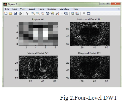
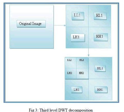
| JPEG2000 is the latest still image compression standard developed by ISO/IEC JTC. Some of the features of JPEG2000 include: multiple resolution representation, region of interest coding.JPEG2000 has a much higher algorithmic complexity. In JPEG2000, encoding is the main process. During the encoding process, an image is partitioned into data matrices called Tiles [11]. In JPEG2000, DWT is a sub band transform which transforms images from the spatial domain to the frequency domain [15]. The 2-D DWT decomposes a tile into LL, LH, HL and HH sub bands. Then LL band can be further, recursively decomposed into next resolution in a dyadic fashion [9]. Four-level DWT decomposition, which results in 13 sub bands has shown in Fig.2. [10] |
| The process called quantization in which the sub band samples generated by the DWT are mapped onto the quantization indices for coding [11]. Generally, it is used to send in terms of coefficient values. In JPEG2000, the Huffman coder is the main block which contains a larger computation time. In order to reduce computation time Tier-1 size is greatly reduced which uses context-based arithmetic coding to encode each code block into independent bit-stream [5]. The Huffman algorithm uses a wavelet transform to generate the sub band samples which are to be quantized. It uses Post-compression rate distortion optimization (PCRD-opt) algorithm for compensating SRAM errors in JPEG2000. The basic principle of Huffman coder is: when coding, it receives a set of quantization coefficients together within a code block. To improve embedding, a fractional bit-plane coding method is used. Huffman coding, which is useful for scalability and for efficient rate control, is actually one of the main features of JPEG2000. Under this fractional coding method, one bit Plane is further decomposed into three passes according to coefficient’s significant situations. While scanning from the top bit plane, allzero bit planes are skipped. Huffman encodes each of the bit-plane in three coding passes. The three coding passes in the order in which they are performed on each bit Plane are significant propagation pass, magnitude refinement pass and clean up pass. Each bit of the code-block is supported by one of these three passes, it sends data to MQ-pair to encode the bit has shown in Fig.3. |
| The adaptive binary arithmetic coder called MQ-CODER is used in JPEG2000 standard. The MQ-CODER utilizes a probability model for its encoding process. This model is implemented as a finite state machine (FSM) of 47 states. It consists of following algorithms: [11] |
| i) CODEMPS algorithm (if most probable symbol has occurred, the CODEMPS algorithm is performed). |
| ii) CODELPS algorithm (if least probable symbol has occurred, the CODELPS algorithm is performed). |
| Another significant block is rate control. Rate control is responsible for improving layer bit-rate targets. This can be achieved by two mechanisms: |
| i) The choice of quantized step size. |
| ii) The selection of subset of the coding to combine the code stream. |
| D. ADAPTIVE ECC |
| Here we use adaptive SECDED schemes where the stronger codes can be derived from weaker but longer codes. We use three different SECDED codes: (72, 64), (39, 32) and (22, 16). Among all these, SECDED codes (22, 16) is the strongest code with an area extension of 37.5% followed by (39, 32) with area extension of 21.9% and (22, 16) with an area increase of 12.5% [14]. The main aspect of these codes is that the parity generator matrix of the shorter code(stronger) can be derived from the parity generator matrix of the longer code(weaker).This can be utilized to design the hardware that can be shared for multiple codes. The parity generator matrix of (72, 64) with (39, 32) code consists of 8 rows (equal to number of parity bits).The first half of code (column 1 to 32) except the seventh row can be used to generate the parity Matrix of (39, 32) code since the seventh row consists of all zeros [14]. These adaptive error control coding schemes introduce little circuit overhead and no additional data storage is needed for these codes. Similarly, the parity matrix of (22, 16) can be derived from the matrix of (39, 32) code by taking into an account the first 16 columns and dropping the all zero row. Error correction code (ECC) techniques have been used to improve memory reliability. Especially, the extended Hamming and odd-weight column codes in the category of single error correction and double error detection (SEC-DED) codes are commonly used [8]. The overall bits computation is eliminated by check bit precomputation during the write operation of memory despite using the error locator and double error detection code, which coincides with those of extended Hamming code. |
| E. SPIHT |
| Set Partitioning in Hierarchical Trees (SPIHT) is an improved version of EZW. Here DWT and SPIHT Algorithm with Huffman encoder are used for further compression and to get enhanced image quality. In this method, more (wide-sense) zero trees are efficiently found and represented by separating the tree root from the tree, so, making compression more efficient. SPIHT does not adopt a special method to treat with it, but direct output.[16]. The actual algorithm used by SPIHT is based on the realization that there is really no need to sort all the coefficients. The main task of the sorting pass in each iteration is to select the coefficient value. This is an important part of the algorithm used by SPIHT. Image data through the wavelet decomposition, the coefficient of the distribution is change into a tree. In this, each coefficient has sub bands namely LH1, HL1 and HH1. The set of coordinates of coefficients is used to represent set partitioning method in SPIHT algorithm as shown in Fig.4. |
RESULTS
|
 |
 |
 |
 |
 |
| |
 |
 |
 |
CONCLUSION
|
| In this paper, we presented various compression techniques such as DCT in JPEG and DWT in JPEG2000 for compensating memory errors. JPEG2000 is widely used as it outperforms JPEG. We also used Adaptive error control coding algorithm to mitigate memory failures caused by aggressive voltage scaling. Huffman coding is mainly used to compress more data. Even though compression is done by the usage of Discrete Wavelet Transform, but it has less amount of reduction in image quality. Because in JPEG2000, there is some loss in quality of image. So SPIHT compression method can be used to increase the quality of the image in addition with Discrete Wavelet Transform which provides; high image quality and better compression ratio. |
Figures at a glance
|
 |
 |
 |
 |
| Figure 1 |
Figure 2 |
Figure 3 |
Figure 4 |
|
References
|
- Y. Emre and C. Chakrabarti, “Data-path and memory error compensation technique for low power JPEG implementation,” school of Eng., Arizona State Univ,
- M. H. Chowdhury and A. Khatun, “Image compression using Discrete Wavelet Transform,” Int. Journal of Comp .Sci., Jahangir Univ, vol. 9, no.1, pp. 327–330,July 2012.
- S. N. Sivanandam, A. PasumponPandian and P. Rani, “Lossy still image compression standards: JPEG and JPEG2000,” Int. Journal of Comp andMgmt., vol. 17, no. 2, pp.69-84, May 2009
- C.Kaur and S.Budhiraja, “Improvements of SPIHT in image compression,” Int. Journal of Emerging Technology and Advanced Engineering., vol. 3,no. 1, pp. 652-656, Jan 2013.
- R. Kaur, H.Singh, J. Singh and S.Kaur, “Literature survey on colour image compression,” IJCST., vol. 4, no. 2, pp. 293–298, June. 2013.
- M. B. Bhammar and K. A. Mehta, “Survey of various image compression techniques,” Int. Journal of Darshan Ins. on Engg, Research and EmergingTechnology., vol. 1, no. 1, pp. 85–90, 2012.
- M. A. Makhzan,A.Khajeh,A.Eltawil and F.J.Kurdahi, “A low power JPEG2000 encoder with iterative and fault tolerant error concealment,” IEEETrans. Very Large Scale Integration (VLSI) syst.,vol.17,no.6,pp.827-837,Jun.2009.
- S. Cha and H. Yoon, “Efficient implementation of single error correction and double error detection code with check bit pre-computation formemories,” Journal of Semiconductor technology and science., vol. 12, no. 4 , Dec 2012.
- B.F. Wu and C.F. Lin, “Analysis and architecture design for high performance JPEG2000 coprocessor,” in Proc. IEEE Workshop., pp. 225-228, 2010.
- D.Modrzyk and M.Staworko, high- performance architecture of JPEG2000 encoder,” European Signal Process. conf., pp. 569–573, Sept. 2011.
- M. Ahmadvand and A. Ezhdehakosh, “A new pipelined architecture for JPEG2000 MQ-coder,” Proc. World Cong on Engg and Comp. Sci., vol. 2,Oct. 2008.
- A. Mansouri, A. Ahaitouf and F.Abdi, “Fast FPGA implementation of EBCOT block in JPEG2000 standard,” Int. Journal of Comp. Sci., vol. 8, no.3, pp. 551–557, Sept 2011
- J. Kim, M. McCartney, K. Mai and B. Falsafi, “Modeling SRAM failures rates to enable fast, dense, low-power caches.” [Online]. Available:http://www.ece.cmu.edu/~truss.
- Y. Emre and C. Chakrabarti, “Memory error compensation techniques for JPEG2000,” in Proc. IEEE Workshop Signal Process. Syst., pp. 36- 41,2010.
- D. U. Shah and R. B. Ambaliya, “Implementation of VLSI based image compression approach on reconfigurable computing system,” Int. Journal ofAdvanced Research in Elect, Electronics and InstEngg, vol. 2, no. 1, pp. 580–583,Jan 2013.
- A. Mallaiah, S. K. Shabbir, T. Subhashini, “A SPIHT Algorithm With Huffman Encoder For Image Compression And Quality Improvement UsingRetinex Algorithm,” Int. Journal of Scientific and Technology Research, vol. 1, no. 5, pp. 45-49, June 2012.
|