International Journal of Innovative Research in Computer and Communication Engineering
ISSN ONLINE(2320-9801) PRINT (2320-9798)
ISSN ONLINE(2320-9801) PRINT (2320-9798)
Ms.Priyanka.G1, Mr.Sundareswari.K2
|
| Related article at Pubmed, Scholar Google |
Visit for more related articles at International Journal of Innovative Research in Computer and Communication Engineering
Vehicular ad hoc networks have been used in wide variety of novel applications such as road safety, multimedia content sharing and commerce on wheels in wireless local area network technologies. Due to the high mobility of vehicles and frequent disconnections, multi hop information dissemination is limited. Currently geographic routing protocols are used for Vehicular ad hoc networks .They do not require route construction and route maintenance phases. Flooding protocol is used to obtain destination position which is reduced in city Environments. In the case of sparse and void regions, there exists a connectivity problem which increases the hop count. Geographic routing protocols use the minimum weighted algorithm to select intermediate intersections. This may lead to numerous intermediate intersections which results in routing paths with higher hop count. In this paper, they propose a hop greedy routing scheme that yields a routing path with the minimum number of intermediate intersections. Back bone nodes play a key role in providing connectivity. It tracks the movement of source as well as the destination and sends the packets to be forwarded in the changed direction. Simulation results signify the benefits of hop greedy algorithm in terms of high packet delivery ratio and shorter end-end delay.
INTRODUCTION |
| THE AUTOMOTIVE industry is currently undergoing a phase of revolution. Today, a vehicle is not just a thermo mechanical machine with few electronic devices; rather, recent advancement in wireless communication technologies has brought a major transition of vehicles from a simple moving engine to an intelligent system carrier. A wide spectrum of novel safety and entertainment services are being driven by a new class of communications that are broadly classified as vehicle-to-vehicle communication and vehicle-to-infrastructure communication. Currently, intelligent transportation system components provide a wide range of services such as freeway management, crash prevention and safety, driver assistance, and infotainment of drivers and/or passengers .Recent trends swing toward advertisement, marketing, and business of services and products on wheels. Consequently, these applications appear to be very lucrative and promising in terms of commerce and research. The significant use of vehicular communications in safety and infotainment applications has re- sulted in the development of a new class of media access control and network layer protocols. The current domain of vehicular research includes routing, congestion control, collision avoid- ance, safety message broadcast, vehicular sensing, security, etc. Different terrains pose separate challenges to vehicular routing. The issues in a city network would not be exactly the same as in a highway or in a delay torrent network. The outskirts may have sparse vehicular density, whereas downtown has to deal with vehicular congestion. The evening may have the highest vehicular traffic, and midnight may be seen as the most silent period of the day. It is a most difficult job to predict the exact traffic density of a region. The structure of the road , number of intersections, number of lanes, length of the road , availability of public transport, and driver behavior have a great impact on the node density and network connectivity of a vehicular network. |
| In a city network, intersections place a unique challenge to routing protocols. A routing protocol has to key on some parameters to decide the routing path. When the routing path is the shortest distance path, it may involve a very high number of change of directions, resulting in higher hop counts. If the connectivity is chosen as the parameter, the most connected road segment would be overcrowded by frequently routing data packets through the same path. As a consequence, the data packets experience longer queuing delays. A third approach suggested in the literature involves broadcasting request messages to fetch the destination position information and connectivity information. However, in a city, flooding is not advisable as multiple nodes would probe for destination position and connectivity information. As a result, every blind search (i.e., flooding) would disrupt all the ongoing communications. In our approach, we choose hop count as the metric to find the routing paths. The hop greedy routing protocol exploits the transmission range and avoids intersections that are used to change the direction of the routing path. It is ensured that the selected intersections have enough connectivity. As the sender decides the routing path proactively, it is not possible to predict the actual connectivity value without probing the whole network. We adopt an indirect method to compute the connectivity parameter for each intersection. |
| Packet congestion will occur as the path with the highest connectivity may be used by multiple source– destination pairs. Hence, we specify a connectivity threshold, and paths having connectivity parameter beyond this threshold are assigned the same connectivity status. Apparently, the multiconstrained optimal path finding problems are known to be NP-hard problems. Thus, we develop an approximation algorithm to choose a path based on both hop count and connectivity. Apart from the routing algorithm, we introduce a back-bone mechanism in which some specialized nodes perform functions such as tracking the movement of end nodes, detecting void regions on road segments, storing packets on unavailability of forwarding nodes, and selecting the most suitable intersection node as the forwarding node. Since the routing algorithm selects a path using destination position, we employ a unicast request-reply-based destination probing mechanism. To implement this approach, we divide the city into many zones that are outlined by the multilane road structures. Some dense intersections (identified as the meeting point of multiple road segments) on the boundary of the zones are chosen as the boundary intersections. |
| As the position of each boundary intersection is known, the unicast request messages initiated by the source can be easily sent to each boundary intersection. The back-bone nodes stationed at boundary intersections then take the responsibility to spread the request messages within the respective zones. The fact that unicast packets do not provide burst traffic and are shielded by request to send/clear to send (RTS/CTS) handshake is the basic motivation to adopt unicast to carry out all con- trol packet transmissions. Once the destination receives the request message, it finds a suitable path to the source and sends the reply. On receiving the reply message, the source forwards data on a routing path computed by the hop greedy routing algorithm. Finally, the routing protocol includes an update mechanism that takes care of interzone movement of end nodes. |
II. RELATED WORK |
| The position-based routing protocol GPSR relies on the location service to acquire the position information of the destination. Basically, it uses two strategies, namely, greedy forwarding and perimeter routing, to send packets from source to destination. In greedy forwarding, a neighbor is chosen as the forwarding node if it has the shortest Euclidian distance to the destination among all neighbors. On the other hand, if no neigh- bor is witnessed closer to the destination than the sender itself, then perimeter routing is exercised. In GPCR, packets are forwarded by applying a restricted greedy forwarding procedure. During the selection of a forwarding node, a junction node termed as the coordinator node is preferred over a nonjunction node. Note that the coordinator node is not necessarily the closest node to the destination. However, the recovery strategy in GPCR remains the same as GPSR. The A-STAR features the best use of city bus route information to identify anchor paths. The main idea behind such arrangement is that more packets can be delivered to their destinations successfully using paths having more connectivity. Geographic source routing uses a static street map and location information about each node. The sender computes a sequence of intersections using Dijkstra’s shortest path algorithm to reach to the destination. The sequence of intersections is placed in the data packet header. The improved GyTAR is an intersection- based geographical routing protocol that finds a sequence of intersections between source and destination considering parameters such as the remaining distance to the destination and the variation in vehicular traffic. The data forwarding between the intersections in GyTAR adopts either an improved greedy forwarding mechanism or a carry-and-forward mechanism, depending upon the availability of the forwarding node. In CAR , the source broadcasts request messages to probe the destination. The request message caches the change of direction information and gathers the connectivity and hop count information en route. On receiving request message, the destination decides the routing path and replies to the source. |
III. SYSTEM IMPLEMENTATION |
4.1 Zone Formation and Boundary Intersection Selection: |
| This section explains how a city map is divided into several zones and how some of the intersections are chosen to be the boundary intersections that are located on the outline of a zone. |
| In city maps similar to those shown in Fig. 1, it is observed that major roads intersect each other, and many polygons are formed out of it. By “major roads,” we mean roads having more than two lanes. The polygonal areas are termed as zones that are the building blocks of a city map. These zones share major roads with the adjacent zones. One such zone formed by four major roads is shown in Fig. 1. Many minor roads are running inside a zone. By “minor roads” we mean roads having less than or equal to two lanes. |
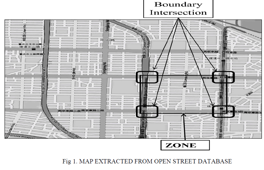 |
| The city map shown in Fig.1 is divided into 20 zones. At the corner of each zone, wider intersections are witnessed. As major roads meet there, it is highly probable that at least one node will be present at that intersection. Wider intersections at the corner a well as on the zone border are termed as the boundary intersections. Basically, the boundary intersections will act as the entry points for the packets sent to a zone. In our system, intersections, major roads, and minor roads are assigned unique IDs. |
| Back-Bone Nodes and Connectivity Preservation: |
| Connectivity is the key requirement for any routing protocol for reliable and fast delivery of packets. A routing path involves many intermediate intersections at which the packet direction is changed. Selection of a wrong intermediate intersection may result in the dropping of packets. Similarly, if the source or destination changes its original position, the ongoing communication may get disrupted. Apart from this, the high mobility of vehicles may create temporary void regions on a road segment. As a result, routing paths passing through such road segments are seriously impaired. In our approach,we allow some of the nodes to take care of the foregoing connectivity issues. Such nodes are called as back-bone nodes. Based on the specific action they perform, they are classified into back-bone nodes at intersection and back-bone nodes at road segments. |
| 4.2 Back-bone nodes at intersection: |
| These nodes are used to maintain connectivity at an intersection. It is necessary for a back-bone node to declare its presence as soon as it enters the intersection region. For this purpose, the periodic beacons cannot be used because the beacon interval might be larger than the duration of stay of a node at an intersection. To overcome this issue, back-bone nodes use positional beacons. |
| 4.3 Back-bone setup: |
| Back-bone nodes of this kind are of three types, namely, stable, primary, and secondary back bones. A stable backbone node is selected from the stream of vehicles waiting at the intersection during red traffic signal. Among the waiting vehicles, the vehicle closest to the intersection declares itself as the stable back bone. However, primary and secondary back bones are selected from the fleet of vehicles crossing the intersection when the signal turns green. |
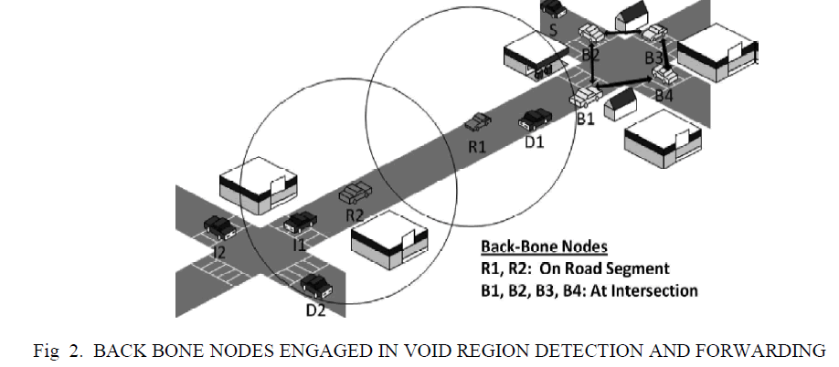 |
| The primary back bone is the one located at the intersection, whereas the secondary back bone is outside the intersection. Initially, a random node declares itself as the primary back bone. Then, the primary backbone node selects a secondary back-bone node comparing the average vehicle speed, the position, and the moving direction of all its neighbors. When the current primary back-bone node leaves the intersection region, it notifies the secondary back bone to become the new primary back bone. This notification also informs vehicles at or around the intersection about the new primary back bone. |
4.4 Packet forwarding: |
| When there is a need to choose a forwarding node from an intersection, a back-bone node is always preferred. This is because back-bone nodes can maintain the communication history and store packet in the absence of a forwarder at the intersection. A forwarding node checks its neighbor list to probe the available back-bone nodes. It compares the packet forwarding time with the staying time of each back-bone node. If the forwarding node is moving, it prefers stable backbone nodes as the forwarder. The primary back bone has higher priority over the secondary back bone. Among the stable back bones, the back bone closest to the intersection has the highest priority. |
4.5 Message queuing and retrieval: |
| The stable back-bone nodes take the responsibility of packet buffering. In the absence of a suitable forwarding node, the packet is stored in a stable back-bone node. On availability of a forwarding node in the desired direction, packet is retrieved and forwarded. The stable back-bone nodes maintain the database of all communications with a timestamp. They store source and destination addresses along with the time of arrival of packets. If a similar packet arrives with a new timestamp, the previous database information is updated. |
| While a packet is being routed along the selected path, either destination or source may change its position and moves to a new road segment. To allow back-bone nodes to keep track ofthe movements, both source and destination inform about their identity in their beacons. Whenever source or destination changes direction, the back-bone node updates the corresponding entry in its communication history. When a packet is being forwarded, the back-bone nodes provide the updated information. This enables a packet to be forwarded in the new direction. In Fig. 2, nodes B1, B2, B3, and B4 represent the back-bone nodes that take care of the activities at intersections. |
4.6 Back-bone nodes at road segment: |
| If any part of a road segment longer than the transmission range is devoid of nodes, it can be noticed by the nodes present at the periphery of the void region. Nodes closest to the void region from both directions declare themselves as back-bone nodes. These backbone nodes are termed as “void-guard” back-bone nodes. The purpose of a “void-guard” backbone node is to inform the presence of a void region to the neighboring back-bone nodes stationed at intersections. For all such transactions among the back-bone nodes, a piggybacked beacon message is used. On being aware of an unconnected road segment, the back-bone node at the intersection prohibits packets from being forwarded to the identified road segment. In this case, the packet is forwarded by selecting a new route. |
IV. CONCLUSION |
| In this paper, I have explored crucial problems such as unreliable location service, intersection node probing problem, etc., experienced by VANET routing protocols. Then propose a hop greedy routing protocol that aims to reduce the end-to-end delay by yielding a routing path that includes the minimum number of intermediate intersections. The zone wise partitioning of a city road network is an important design framework for the efficient functioning of the destination discovery procedure. The hop greedy algorithm finds the best possible path in terms of both hop count and connectivity. To address connectivity issues such as void regions and unavailability of forwarders, the concept of back-bone node is introduced. Moreover, by employing unicast request messages, the proposed routing scheme eliminates packet loss and congestion noticed in contemporary routing protocols that use broadcast request messages. I propose an update procedure that is very effective to deal with destination movements. The simulation results confirmed that the packet generation rate, the distance between the source and the destination, and the distance of destination movement do not have a large impact on the performance of the proposed scheme, which outperforms GPCR and GyTAR in terms of packet delivery ratio and endto- end delay. |