International Journal of Advanced Research in Electrical, Electronics and Instrumentation Engineering
ISSN ONLINE(2278-8875) PRINT (2320-3765)
ISSN ONLINE(2278-8875) PRINT (2320-3765)
Warsha Kandlikar1, Toradmal Savita Laxman2, Deshmukh Sonali Jagannath2
|
| Related article at Pubmed, Scholar Google |
Visit for more related articles at International Journal of Advanced Research in Electrical, Electronics and Instrumentation Engineering
The world is being 3d and the 3d imaging having more advantages over 2d,presently there are attendance system based on fingerprint recognition but that are having some advantages like the surface should be dust free and also we have the contact with the sensor so that finger should have to keep properly. There are also 2D face recognition based attendance system. To overcome the problems in 2d i.e. Lighting variations, Expression variations, variations 3D face recognition is used. We propose a system that takes the attendance of the student using Conversion of 2d images into 3d And then face face detection and recognition . We are using two 2d images taken from two different camera and that is converted into 3d image using binocular disparity technique. After this image is use for the face recognition. Threedimensional face recognition (3D face recognition) is a modality of facial recognition methods in which the threedimensional geometry of the human face is used. It can also identify a face from a range of viewing angles, including a profile view. Three-dimensional data points from a face vastly improve the precision of facial recognition.
Keywords |
||||||||||
| 3d conversion, stereo imaging, binocular disparity, face recognition | ||||||||||
INTRODUCTION |
||||||||||
| We are developing the attendance system using 3d face recognition technique. Two web cameras are used to capture the facial image which calibrated by using stereo camera calibration technique. Web camera image is used to analyze facial characteristics such as the distance between eyes, mouth or nose. These measurements are stored in a database and used to compare with a subject standing before a camera. | ||||||||||
| In this system the standard images of the students in that class are stored in the database. The stored image has the Students information such as the student’s roll number, class, year etc. The image are captured from two different cameras which are placed parallel and calibrated one with respect to other. The camera is converted into 3d image. Face image is detected from the captured image and recognized and then image is compared with the reference images stored in database. Then attendance of the student is marked. | ||||||||||
| For conversion of 2d images into 3d image binocular disparity algorithm is used in which two or more 2d images are used for conversion. First the disparity image is obtain from two images then disparity image is converted to 3d and for face detection haar cascade is used and for recognition eigen faces technique is used. | ||||||||||
SURVEY |
||||||||||
| 2D to 3D conversion is the process of transforming 2D ("flat") film to 3D form. 2D to stereo 3D conversion Also called stereo conversion. The vast majority of face recognition system use typical intensity images of the face. We refer to these as “2D images.” In contrast, a “3D image” of the face is one that represents three-dimentional shape. The world of 3D incorporates the third dimension of depth, which can be perceived by the human vision in the form of binocular disparity. | ||||||||||
| An important step in any 3D system is the 3D content generation. Several special cameras have been designed to generate 3D model directly. For example, a stereoscopic dual-camera makes use of a co-planar configuration of two separate, monoscopic cameras, each capturing one eye’s view, and depth information is computed using binocular disparity. 2D to 3D conversion method recovers the depth information by analyzing and processing the 2D image structures. Depending on the number of input images, we can categorize the existing conversion algorithms into two groups: algorithms based on two or more images and algorithms based on a single still image. Here we are using the second method i.e. Using two images. | ||||||||||
Depth-based conversion |
||||||||||
| Most semiautomatic methods of stereo conversion use depth maps and depth-image-based rendering. The depth map is a separate grayscale image having the same dimensions as the original 2D image, with various shades of gray to indicate the depth of every part of the frame. | ||||||||||
Binocular disparity : |
||||||||||
| With two images of the same scene captured from slightly different view points, the binocular disparity can be utilized to recover the depth of an object. This is the main mechanism for depth perception. First, a set of corresponding points in the image pair are found. Then, by means of the triangulation method, the depth information can be retrieved with a high degree of accuracy when all the parameters of the stereo system are known. When only intrinsic camera parameters are available, the depth can be recovered correctly up to a scale factor. In the case when no camera parameters are known, the resulting depth is correct up to a projective transformation. | ||||||||||
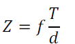
| Assume And Are the projections of the 3D point P on the left image and right image; And Are the origin of camera coordinate systems of the left and right cameras. Based on the relationship between similar triangles (p, Pl,Pr) and (p,ol ,Or ) shown in Figure,the depth value Z of the point P can be obtained: | ||||||||||
 |
||||||||||
| Where d xr-xl Which measures the difference in retinal position between corresponding image points. The disparity value of a point is often interpreted as the inversed distances to the observed objects. Therefore, finding the disparity map is essential for the construction of the depth map. Epipolar geometry and camera calibration are the two most frequently used constraints. With these two constraints, image pairs can be rectified. Another widely accepted assumption is the photometric constraint, which states that the intensities of the corresponding pixels are similar to each other. The ordering constraint states that the order of points in the image pair is usually the same. | ||||||||||
RELATED WORK |
||||||||||
| System development consist of three major steps i.e. 2d to 3d conversion, face recognition and attendance system. | ||||||||||
A. Conversion Of 2D Images Into 3D |
||||||||||
| Binocular stereo uses only two images, taken with cameras that were separated by a horizontal distance known as the "baseline. Calibrating the stereo camera system allows us to compute the 3-D world points in actual units, such as millimetres relative to the cameras. The process consists of the following steps. | ||||||||||
| 1. Calibrate the stereo camera system: | ||||||||||
| Calibration Involves the estimation of the intrinsic parameters of each camera. It also includes the estimation of the translation and rotation of the second camera relative to the first one. These parameters can be used to rectify a stereo pair of images to make them appear as though the two image planes are parallel. The rectified images are then used to compute the disparity map required to reconstruct the 3-D scene. A typical calibration pattern is an asymmetric checkerboard. | ||||||||||
| 2. Rectify a pair of stereo images: | ||||||||||
| Rectification is an important pre-processing step for computing disparity, because it reduces the 2-D stereo correspondence problem to a 1-D problem. Rectified images appear as though the two image planes are parallel and rowaligned. This means that for each point in image 1, its corresponding point in image 2 lies along the same row. | ||||||||||
| 3. Compute disparity: | ||||||||||
| The distance in pixels between corresponding points in the rectified images is called disparity. The disparity is used for 3-D reconstruction, because it is proportional to the distance between the cameras and the 3-D world point. | ||||||||||
| 4. 3D reconstruction: | ||||||||||
| Reconstruct the 3-D world coordinates of points corresponding to each pixel from the disparity map. | ||||||||||
B. Face Recognition |
||||||||||
| Face recognition is the process of putting a label to a known face. Just like humans learn to recognize their family, friends and celebrities just by seeing their face, there are many techniques for a computer to learn to recognize a known face. It involve four main steps: | ||||||||||
| 1. Face detection : It is the process of locating a face region in an image. | ||||||||||
| 2. Face preprocessing : It is the process of adjusting the face image to look more clear and similar to other faces (a small grayscale face in the top-center of the following screenshot). | ||||||||||
| 3. Collect and learn faces: It is the process of saving many preprocessed faces and then learning how to recognize them. | ||||||||||
| 4. Face recognition : It is the process that checks which of the collected people are most similar to the face in the camera. | ||||||||||
RESULT AND DISCUSSION |
||||||||||
| For calibration we have taken fourteen pairs of image. From which we get intrinsic and obtained extrinsic camera parameters. These parameters are used for finding the disparity map. | ||||||||||
| Here we have used standard images for conversion of 2d image into 3d. As shown in above figure (a) Is left image and figure(b) right image. The figure3 shows the disparity image computed from left and right image. This disparity image then use to reconstruct the 3d image the following fig shows 3d reconstructed image shown in 3d viewer. | ||||||||||
CONCLUSION |
||||||||||
| We have done the conversion of 2d images into 3d. Recognition and analysis of 3D face image have more challenges and difficult to implement for 3D face recognition based attendance system So that we have used the 2D image for recognition and attendance estimation. | ||||||||||
FUTURE WORK |
||||||||||
| We are developing system for 10 to 15 student’s attendance so it can be extended to the class also with large database. Also using more than two images for the reconstruction of 3D image there will be more accuracy in disparity image that can be used for face recognition. | ||||||||||
ACKNOWLEDGMENT |
||||||||||
| Authors wish to acknowledge all the individuals who helped directly and indirectly for this research. The guidance and support received from all the members who contributed and who are contributing to this project, was vital for the success of the project. I must mention thanks to several individuals and organization that were of enormous help in the development of our work. | ||||||||||
Figures at a glance |
||||||||||
|
||||||||||
References |
||||||||||
|


