ISSN ONLINE(2278-8875) PRINT (2320-3765)
ISSN ONLINE(2278-8875) PRINT (2320-3765)
| Asaad Musaab Ali Yousif1, Adamu Halilu Jabire2, Gsimalseed ALI Gsimalseed Gsimalla3 Masters Student, Dept. of Electronics, Tianjin University of Technology and Education, Tianjin, China |
| Related article at Pubmed, Scholar Google |
Visit for more related articles at International Journal of Advanced Research in Electrical, Electronics and Instrumentation Engineering
This paper describes the design and implementation of induction motors breakdown observation based on atmega32 microcontroller. This paper proposes an approach to Good motor protection, this has to cover all possible problem areas. It must not be tripped before the motor is put at risk, if the motor is put at risk, the protection device has to operate before any damage occurs, If damage cannot be prevented, the protection device has to operate quickly in order to restrict the extent of the damage as much as possible. Protection and controls the motor from the Phase failure, unbalanced voltage and phase sequenceisone of the major functions of most control systems. The experiment showed that the system for protection and controlling induction motor can be used stably and reliably.
Keywords |
| induction motors, Phase failure, unbalancedvoltage, phase sequence and protection |
INTRODUCTION |
| Induction motors are complex electro-mechanical devices utilized in most industrial applications for the conversion of power from electrical to mechanical form. Induction motors are used worldwide as the workhorse in industrial applications. Such motors are robust machines used not only for general purposes, but also in hazardous locations and severe environments. General purpose applications of induction motors include pumps, conveyors, machine tools, centrifugal machines, presses, elevators, and packaging equipment. On the other hand, applications in hazardous locations include petrochemical and natural gas plants, while severe environment applications for induction motors include grain elevators, shredders, and equipment for coal plants. Additionally, induction motors are highly reliable, require low maintenance, and have relatively high efficiency. Moreover, the wide range of power of induction motors, which is from hundreds of watts to megawatts, satisfies the production needs of most industrial processes [2]. |
RELATED WORK |
| For example PalashKundu and Arabinda Das proposed a prototype detection system based on 8085 microprocessor /8751 microcontroller has been developed for identification of phase sequence and detection of phase unbalance. Proposed microprocessor based detection system can generate unique codes for different probable permutations for supply system. System is capable to identify phase sequence of three phase supply system and can identify phase sequence during fluctuation of power frequency within recommended value. System can detect phase sequence within a cycle and can identify and protect system form any unbalance condition instantaneously [1]. |
| For example Aderiano M. da Silva, B.S. proposed induction motor fault diagnosis is based on the analysis of the envelope of the three phase stator current. This diagnostic method can classify two types of induction motor faults: broken rotor bars and inter-turn short circuits in the stator windings. Experimental results show that the three phase current envelope is a powerful feature for motor fault classification. The envelope signal is extracted from the experimentally acquired stator current signals and is used in conjunction with machine learning techniques based on Gaussian Mixture Models (GMMs) and Reconstructed Phase Spaces (RPSs) to identify motor faults. The second method presented in this thesis is an induction motor fault monitoring technique based on the air gap torque profile analysis, associated with machine learning techniques to classify the operating condition of an induction motor as healthy or faulty. These machine learning techniques are based on GMMs and RPSs [2]. |
CASE STUDY |
| Here we take up our system for motor protection and control we classified our design into three problems Phase failure, unbalanced voltage and phase sequence. |
[A] Phase failure: |
| Phase failure occurs when power is lost to one of the lines supplying power to a three-phase motor. The motor will continue to operate but will draw an excessive amount of current. In this condition, the overload relay should cause the motor starter to disconnect the motor from the power line if the overload heaters have been sized correctly. Single phasing will cause the two phases that remain energized in a three-phase motor to increase current by an average of 173% [3]. |
[B] Unbalanced voltage: |
| By measuring voltages from Line 1 to Line 2, Line 2 to Line 3, and Line 3 to Line 1, and performing a few simple calculations, a technician can determine if there is a voltage unbalance problem. Voltage unbalance exceeding more than 2 percent in three-phase systems can cause current unbalance among the windings. These, in turn, can cause an increase in winding temperature and an overheating problem that can be harmful to the motor [3]. |
[C] Phase sequence: |
| If two of the lines supplying power to a three-phase motor are reversed, it will cause the motor to reverse the direction of rotation. This can be a serious problem with some types of equipment. Unintended reversal of direction can cause gear teeth to shear, chains to break, and the impeller of submersible pumps to unscrew off the end of the motor shaft. It can not only cause damage to equipment but also injury to operators or personnel in the vicinity of the machine [3]. |
WORKING |
| The main objective of this system is to protect the motor from phase failure, phase unbalance and phase insequence which can be achieved using microcontroller atmega8. All the manual operations are replaced by sending signals from the microcontroller to the main contactor.The working of the design can be classifiedinto four phases: |
[A]phase sequence identification |
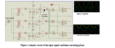
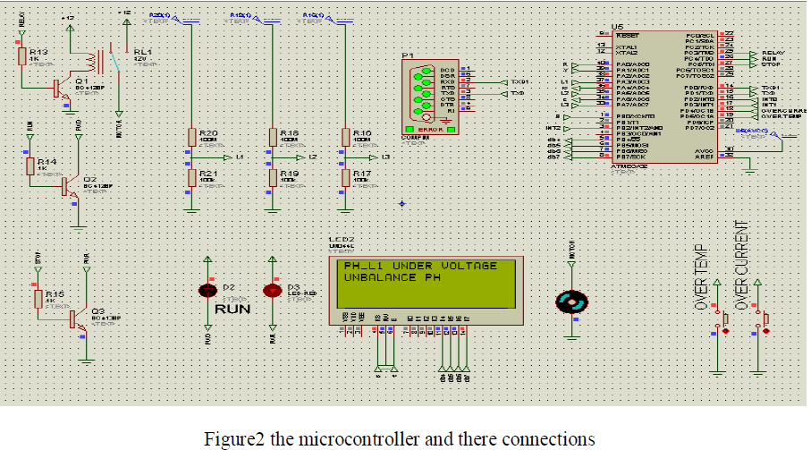
| The system start converting the three phase input power supply into pluses which can be easy to identify the phase in sequence or not,Figures 1&2 below shows the schematic circuit and there signals. we used flip flop to identify the shift between the three lines is normal or abnormal, the flip flop is used to read the value of input when is receive clock pulse, we apply the pulse of line1 to the all flip flop to detect the sequence is correct and the angle shift is 120,240 respectively related to line1.the output of flip flop applied to the microcontroller pins. |
[B]phase failure and phase unbalance identification |
| Through ADC pins of microcontroller the system also can read the value of voltage for the three line to identify the under voltage, over voltage and unbalance voltage between the three lines and also to detect if one line or more is failure. |
[C]User Interface Panel |
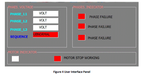
| We used visual basic to design the UIP for observation of motor behavior it can offer you the voltage of three lines (L1, L2&L3), indication of the phase sequence, indication of under-over voltage, indication of unbalance voltage and phase failure indication contiuosly.figure4 shows the form of UIP. |
[D] Microcontroller processing |
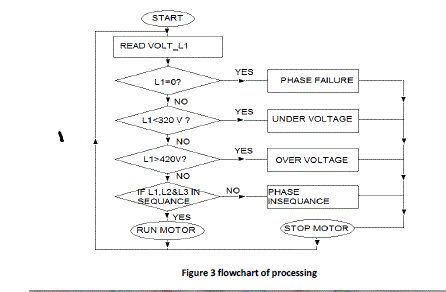
| The microcontroller read the data from input pins and startsprocessing,update informationand send it to visual basic through RS232 or LCD directory from microcontroller.Figure3 shows the flowchart of processing. |
 |
 |
 |
 |
SIMULATION & RESULTS |
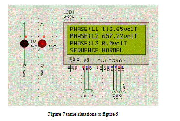
| We used Bascom compiler to write the code for the system, in addition to that we used proteus to implement the schematic circuit of the design and visual basic 6 for user interface panel through the RS232 protocol .the figures 5-6-7 shows the result of the design. |
CONCLUSION |
| Complexity of system has been simplified, by this proposal. Induction motor by this design it have good protection from Phase failure, phase unbalance and phase sequence. In addition to that the cost effective. |
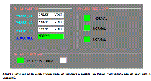 |
| Figure 5 show the result of the system when the sequence is normal –the phases were balance and the three lines is connected. |
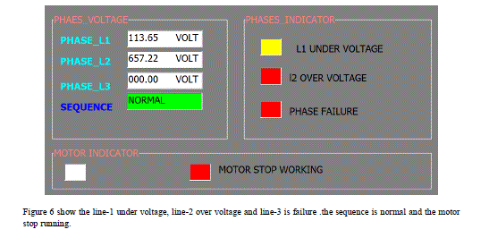 |
| Figure 6 show the line-1 under voltage, line-2 over voltage and line-3 is failure .the sequence is normal and the motor stop running. |
 |
References |
|