Keywords
|
| APS Antenna Pointing System, Look Angle, Microcontroller, Digital Controller Card (DCC). |
INTRODUCTION
|
| Antenna Control System for the CSR MKII Radar will control all electrical functions. It will rotate Antenna continuous in Azimuth at different speeds. Azimuth Control System consists of two sub-systems Azimuth Control Unit and Motor Drive Unit (MDU) forming part of the Pedestal assembly of CSR MK-II system. AZCU is the main control part which houses the controller and other electronics. It provides commands to Motor Drive Unit, which drives the motor for continuous rotation of antenna in azimuth at different speeds (1 to 60 RPM). AZCU is an environmentally sealed enclosure, a microcontroller based system. |
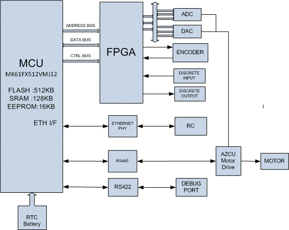
| The Azimuth angle feedback is through an 18-bit encoder (SSI Interface). AZCU will interface with main system controller on Ethernet (10/100 Mbps LAN) to provide all interlocks/feedbacks as status data on query or at regular intervals. It interfaces with Portable Drive Unit to receive rotation commands in both directions using discrete inputs through switches. Motor Drive Unit (MDU) will be basically housing the 3-Phase drive for control of motor; speed commands to the MDU will be given by AZCU. Block diagram is given below for Antenna Control System. |
| Azimuth Control System consists of two sub-systems Azimuth Control Unit and Motor Drive Unit (MDU) forming part of the Pedestal assembly of CSR MK-II system. AZCU is the main control part which houses the controller and other electronics. It provides commands to Motor Drive Unit, which drives the motor for continuous rotation of antenna in azimuth at different speeds (1 to 30 RPM in steps of 1RPM and in discrete steps of 5 RPM beyond 30 RPM up to 60 RPM). AZCU is an environmentally sealed enclosure, a microcontroller based system. |
| This paper also describes about the Design of the antenna pointing system in detail. The entire Design aspects have been divided into hardware, software and Industrial design. The control algorithm & communication capabilities are implemented on a microcontroller platform. The second section describes about the Need of the Design followed by the functional, Interface, and protocol requirements of the APS as third section. |
SYSTEM OVERVIEW
|
| This project is reveals about the design and development for antenna control system. Antenna Control System for the Coastal Surveillance Radar (CSR MKII) will control all electrical functions. It will rotate Antenna continuously in Azimuth at different speeds. Azimuth control system consists of two sub-systems, Azimuth Control Unit (ACU) and Motor Drive Unit (MDU) forming part of the Pedestal assembly of CSR MK-II system. AZCU is the main control part which houses the controller and other electronics. |
| It provides commands to Motor Drive Unit, which drives the motor for continuous rotation of antenna in azimuth at different speeds (1 to 30 RPM in steps of 0.5 RPM and in discrete steps Size of 5 RPM beyond 30 RPM up to 60 RPM). AZCU is an environmentally sealed enclosure, a microcontroller based system. |
POWER SUPPLY REQUIREMENTS
|
| The 230 VAC which enters the ACU through Connector 230VAC EMI filter it reaches to 230 VDC Switch on the front panel of the unit. Once Switch is made On the 230 VAC will reach all over the system and 230 V LED and 24VDC LED will glow. The 230VAC is converted to 24VDC from power supply 1card and through 24V EMI filter it is distributed all over the system, PDU and Drive. Power Supply 2 card takes 24 V DC as input and Converts to 3V3, 5V and ±15V. The +15V is given to encoder through connector. |
| a. AC Input : 230V±10%, 1-Ph, 50 Hz |
| b. 24VDC/4A generation will be inside the unit |
DRIVE & MOTOR INTERFACE
|
| The 24VDC is the given to alarm through Relay and Relay is controlled by DO channel of Controller card. The Brake released feedback signal is also received as Digital Input to the controller card. The Unit supplies 24VDC to the PDU and receives Commands. |
| a. Drive interface will be discrete input & output signals (24V), Analog speed & Modbus RS485 interface. |
| b. It will interface with motor drive unit for giving enable and stop, Forward & Reverse run, speed setting Commands etc. |
| b. It will interface with motor drive unit for giving enable and stop, Forward & Reverse run, speed setting Commands etc. |
Encoder Interface
|
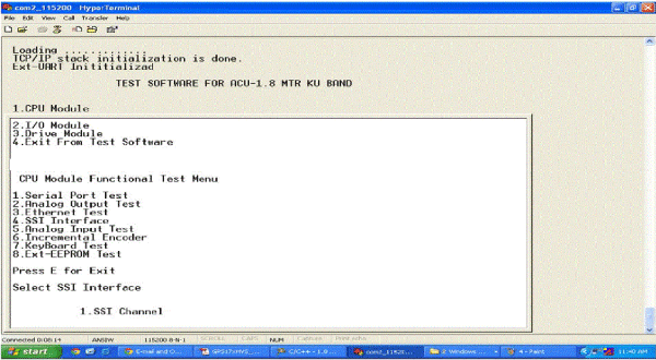
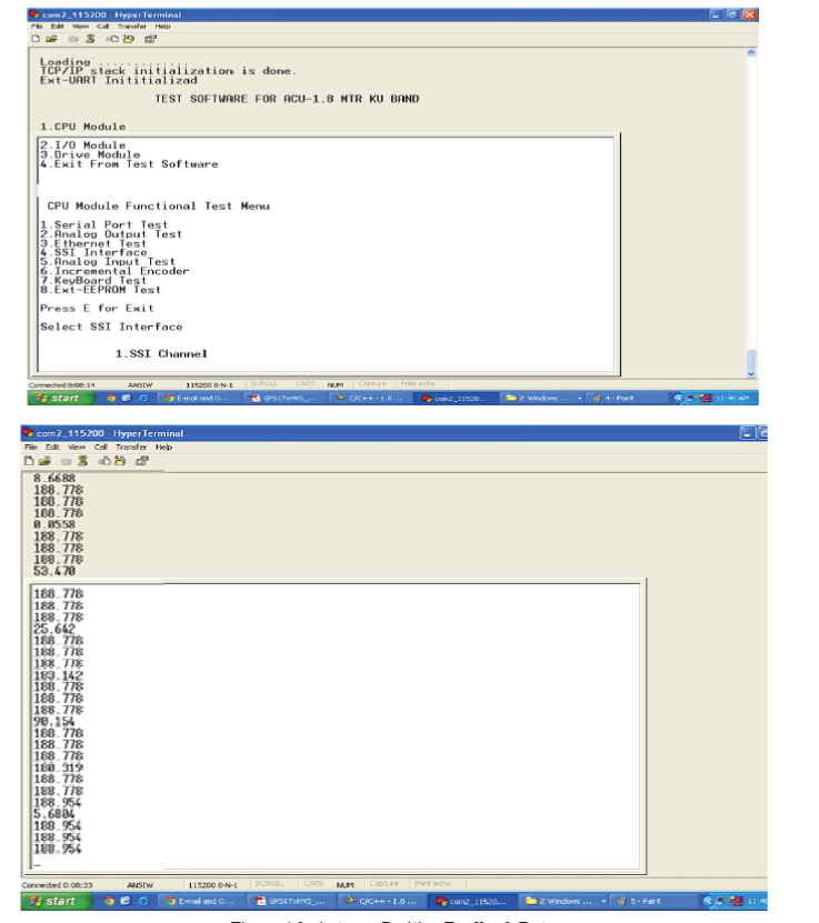
| The 18 bit SSI Encoder is used to get position information of antenna in azimuth axis. We have designed SSI channel Interface is for azimuth axis. Once the user enters 1, SSI Encoder Test is selected and the antenna position is continuously feedback from the encoder. |
| AZCU will interface with an 18-bit single turn absolute encoder. |
| a. Synchronous Serial Interface(SSI): RS422 |
| b. 15V ±10% DC as power supply input to encoder |
| c. Output Code – Binary |
Radar Interface
|
| The Antenna Control System will interface with radar controller through rotary joint over Ethernet interface for receiving commands in remote mode and also sends status. |
| AZCU will interface with radar controller on LAN communication (TCP/IP) at 10/100 Mbps for |
| a. Health, Software, Antenna Position & RPM etc on query. |
| b. Start & Stop rotation, Set RPM, go to specific Azimuth etc. |
Portable Drive Unit Interface
|
| PDU will be a switch box with illuminated pushbutton switches (IPBs) & LEDS. |
| a. Power ON LED |
| b. PDU enabled IPB |
| c. PDU Speed-1/2 IPB |
| d. PDU FWD Start/Stop IPB |
| e. PDU REV Start/Stop IPB |
AZCU Controller Card Specifications
|
| Controller Card will be using 32-bit MCU core from ARM’s Cortex-M class. It includes IEEE 1588 Ethernet, full- and high-speed USB 2.0, inbuilt EEPROM and program flash with a rich suite of analog communication, timing and control peripherals. The controller card also interfaces with the other devices through Serial ports, Ethernet, SSI and DAC. |
Following are the specifications:
|
| a. Controller : |
| ? MK61FX512VMJ12:K61 |
| ? FLASH :512 KB |
| ? SRAM :128 KB |
| ? EEPROM :16 KB |
| b. Input Power Supply-Card:24VDC±10% |
| c. On-Board DC-DC Convertors : +3.3V, +5V, ±15V |
| d. Serial Ports(card) |
| ? Serial Port-1 : RS232(M&C Interface) |
| ? Serial Port-2 : RS232/RS422 configurable(Spare) |
| ? Serial Port-3 : RS485(Spare) |
| ? Serial Port-4 : RS422 |
| e. Ethernet (10/100Mbps): Radar Controller. |
| f. DAC Interface : 16-bit, 2 Channels (±10VDC o/p) |
| g. ADC Interface: 4 nos. (±10VDC Input), 14-bit ADC. |
h. Digital Inputs
|
| No. of Channels : 12 independent floating channels each one fitted With Opto coupler |
| ? Input voltage : Nominal Voltage 24V (19V to 36V) |
| Logic High - >12 VDC |
| Logic Low - <10 VDC |
| ? Input overvoltage : Up to 30% nominal for extended periods. 300% for transitory peaks. |
| ? Channel protection : provided |
| ? Input current (ON) : 3 to 5 mA per channel |
| ? Over voltage Protection : provided |
| ? Built in Test |
| ? LED indication for all Digital Inputs |
| ? Spike Suppression up to 50V. |
| ? Galvanic isolation >500V on all channels with respect to TTL lines. |
Digital Outputs
|
| ? No. of Channels : 12 discrete output channels (Sinking type) |
| ? Output Standard : Opto couplers with 50VDC @ 50 mA Output open- collector phototransistors |
| ? Built in Test |
| ? LED indication for all Digital Outputs. |
FPGA
|
| In this project, FPGA is used as an interface between the controller and hardware blocks. The hardware blocks consist of ADC, DAC, SSI, Digital Inputs, and Digital outputs. The FPGA contains all the needed circuit with different addresses mapped. |
| ? Lattice XP2 : LAXP2-8E-5 QN208E or equivalent |
| ? 40 MHz Clock |
k. Battery for Real Time Clock
|
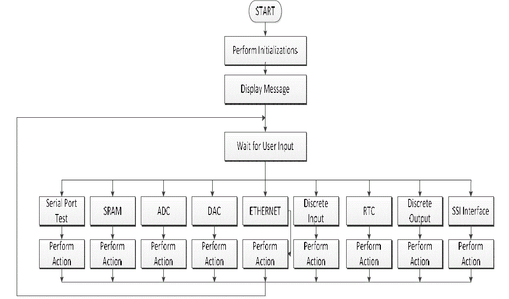
| Test Software: The objective of this project is to design and implement the test software for CSR Mark-II controller card and the peripherals like ADC, DAC, Discrete Input/output, Ethernet and Serial port. The test software shall be used to test the peripherals of controller card. The test software developed on C language using code warrior tool and it is based on microcontroller with ARM Cortex-M4 architecture. |
| The developed software shall communicate with motor drives and radar controller to position the Antenna with minimum tolerance in a closed loop system by taking feedback of Antenna position i.e. in terms of angle from 0 to 360 degree from Encoder and also keeps count of number of complete rotations made by the Antenna. |
ABOUT CONTROLLER UNIT
|
ACS – CSR MKII Test Software
|
| ? The Test software for ACS – CRS MKII will be developed using FreescaleCode warrior 10.X tool. |
| ? The application software lies in flash area of the controller. |
| ? Software is developed using ‘C’ programming. |
| ? Software is responsible for the following interfaces, |
| 1. Serial Ports |
| 2. ADC |
| 3. DAC |
| 4. External SRAM |
| 5. Discrete Inputs/Discrete Outputs |
| 6. Ethernet |
| 7. RTC |
CONCEPT OF EXECUTION
|
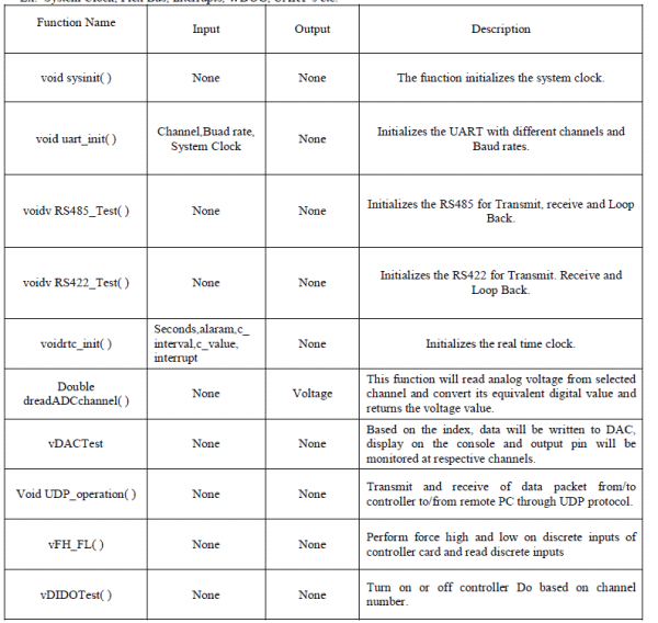
System Initialization and Interface Tests
|
| This will initialize the required module/peripheral of MK61FX512VMJ12 controller to perform different operations. Ex: System Clock, Flex Bus, Interrupts, WDOG, UART`s etc. |
 |
ADC Interface
|
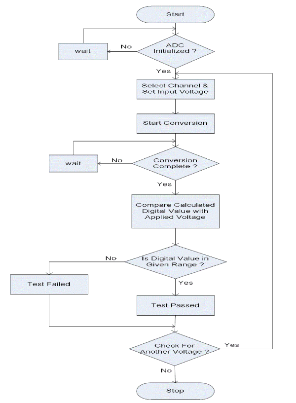
| These are 4 Analog signals and these signals are configured as input signals. The range of the analog signal is -10V to +10VDC. Test setup shall generate the all of analog signals and the same shall be verified by the HOST system. |
 |
DAC Interfaces
|
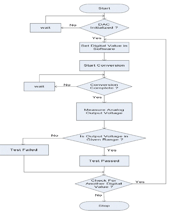
| As discussed, the method chosen for controlling the voltage across the motors is of varying the duty cycle with a pulse width modulation [PWM] scheme. The DC voltage is converted to a square wave signal thereby varying the duty cycle of the signal and average power delivered to the motor is varied and hence the motor speed. Thereby, various DAC outputs is used to drive the motor at different speeds.. |
 |
Ethernet Interface
|
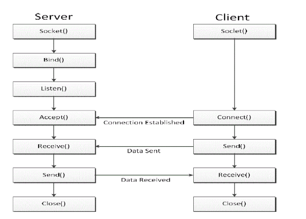
| The Host PCis installed with pedestal tester software which shall communicate with pedestal unit through Ethernet LAN interface with the specified set of commands and data. |
 |
Discrete Input/Discrete Output Interfacing
|
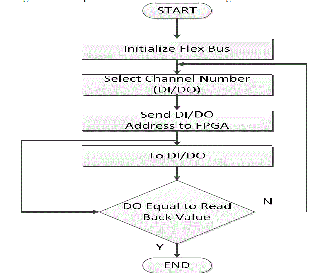
| Controller card will interface with discrete input and discrete output cards. This operation will perform read and write operations onto discrete channels. DI is used to read the status of antenna system. DO are used to control the antenna control system. The respective DO channels are turned based on feedback signals and the status of the antenna system. Each DO is tested by writing 1 or 0 to respective channels and then reading back the status of individual DO. |
 |
Test Results
|
| After connecting the serial port of PC to M&C port of controlled card and when the system is powered up, initially the POST, memory testing will be carried out then the control is given over to the user. |
SSI Encoder Test Result
|
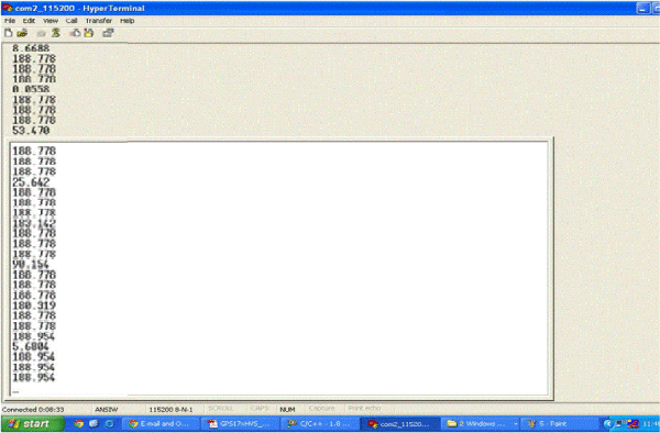
| 18 bit SSI Encoder is used to get position information of antenna in azimuth and elevation axis. We have designed SSI channel Interface for azimuth axis. Once the user enters 1, SSI Encoder Test is selected and the antenna position is continuously feedback from the encoder. A resolution of 0.005 degree change in antenna position can be seen in figure 4.3. |
DAC Test Result
|
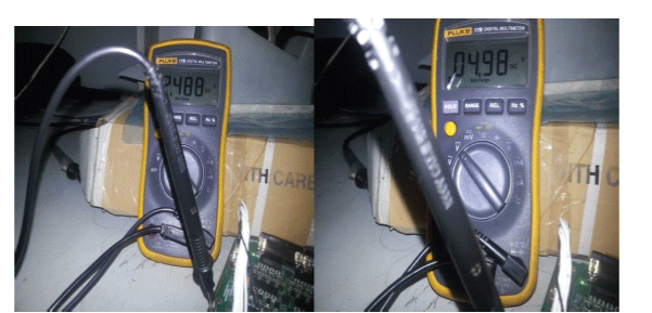
| As discussed, the method chosen for controlling the voltage across the motors is of varying the duty cycle with a pulse width modulation [PWM] scheme. The DC voltage is converted to a square wave signal thereby varying the duty cycle of the signal and average power delivered to the motor is varied and hence the motor speed. Thereby, various DAC outputs is used to drive the motor at different speeds.. A +5V, +2.5V output generated as seen in figure 4.4 delivers a 50% and 25% duty cycle across load. |
 |
ADC Test
|
| There are 4 Analog signals and these signals are configured as input signals. The range of the analog signal is -10V to +10VDC. Test setup shall generate the all of analog signals and the same shall be verified by the HOST system. |
 |
CONCLUSION & FUTURE SCOPE
|
| From the Experimental results, the APS is able to track the target by moving to the required angle. But that is depending upon the Heading and GPS values. . Even though this project demands the usage of minimal peripherals of the microcontroller, the design is carried out as a Generic Embedded board which can be used as a development board for any new projects. This is the advantageous factor of this design. The APS has been designed in a Generic approach with rich peripheral combination that can be easily used for variety of applications. The various applications that can be used are Remote Video Terminal (RVT), Ground Antenna control unit, and Micro air vehicle drive control. The same system can be extended APS to do automatic pointing of the target by moving the antenna in dual axis namely azimuth and elevation. The close loop position control of the antenna is achieved with the help of potentiometer sensors. The degree of freedom in azimuth is 0 deg to 360 deg and the elevation is 0 deg to 90 deg. |
Figures at a glance
|
 |
 |
 |
 |
| Figure 1 |
Figure 2 |
Figure 3 |
Figure 4 |
|
References
|
- K61 Sub-Family Reference Manual
- Paul Horowitz Winfield Hill, The Art of Electronics, Cambridge University Press 1993
- KVH Industries. KVH Compass Engine Technical Manual. 2005
- Dtn Bone - Delay Tolerant Networking Research Group, http://www.dtnrg.org/wiki/Home.
- G. Dias, R. Salles, "Epidemic SIR Model Applied to Delay-Tolerant Networks", 30th BRAZILIAN TELECOMMUNICATIONS SYMPOSIUM (SBrT 2012), Sep. 2012.
- Equi rectangular Projection www. wikipedia.org
|