ISSN ONLINE(2278-8875) PRINT (2320-3765)
ISSN ONLINE(2278-8875) PRINT (2320-3765)
Reenu George1, Manoj G2, S. Kanthalakshmi3
|
| Related article at Pubmed, Scholar Google |
Visit for more related articles at International Journal of Advanced Research in Electrical, Electronics and Instrumentation Engineering
This paper describes the design and implementation of microstepper motor drive and a control system for two-phase hybrid stepper motor. Based on LM3S6965 arm processor, this paper proposes an approach to subdivide the step to microstep with required number of steps for stepper motor to improve positioning accuracy. Sine/cosine microstepping method is used to adjust the current in each winding of the stepper motor. This paper describes the running of motor at different speeds by changing the number of samples per rotation and position control by number of samples. The experiment showed that the system for controlling stepper motor can be used stably and reliably
Keywords |
| Stepper motor, microstepping, arm processor, control system, LM3S6965. |
I.INTRODUCTION |
| Stepper motors are electromechanical devices that convert electrical pulses into discrete mechanical movements. Owing to their precision, robustness and reliability, they have a wide range of application in robotics and computer peripherals.The precision and performance criteria of stepper motors can be enhanced using segmentation technology [1]. In microstepping drive, one full step is broken into many discrete steps by continuously varying the current in the winding. The audible noise due to discontinuous stepping and resonance effect can be reduced by microstepping. Increase in rotor position resolution can be achieved by microstepping. All stepping modes are derived from the sinusoidal mode by adjusting the granularity of the driving sine wave [2]. Full step and half step consist of 90 degree and 45 degree of one sine wave period respectively. In microstepping, the motor basic steps (1.8 degree) are divided into number of steps by pulse width modulation (PWM) technique. Many microcontrollers can be used to control a stepper motor, such as 80C196MC, AT89C51, and PIC microcontrollers. However, depending on the complexity of the control algorithm (i.e., microstepper and current limiting), it can be advantageous to choose a microcontroller with selected peripherals that will take care of most of the stepper motors overhead [3]. The arm cortex processor provides a high performance, low-cost platform that meets the system requirements of minimal memory implementation, reduced pin count, and low power consumption, while delivering outstanding computational performance and exceptional system response to interrupts. The LM3S6965 arm processor is targeted for industrial applications, including remote monitoring, test and measurement equipment, network appliances and switches, factory automation, HVAC and building control, gaming equipment, motion control, medical and instrumentation [4]. The LM3S6965 controller contains three generator blocks and generates six independent PWM signals or three paired PWM signals with deadband delays inserted. In the proposed work, PWM signals and motor controls are generated with LM3S6965 arm processor. |
II.MICROSTEPPING DRIVE |
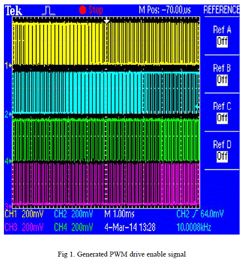
| Microstepping is a stepper motor technology that controls the current in the motor winding, where the number of steps can be increased by manipulating the current that the controller sends to the motor during each step and the resonance problem can be reduced using microstepping at a low step rate. Microstepping mode, which consists of sine and cosine wave forms, is used to drive the hybrid stepper motor instead of discrete pulses [5]. Sine and cosine equivalent pulse width modulation (PWM) pulses are generated using LM3S6965 to enable the drivers. In this scheme, sine cosine waves are applied to two-phase bipolar stepper motor windings. Sine/cosine waves are derived by varying the duty cycle in percentage of sine and cosine values. The pulse width of PWM pulses is proportional to the sine and cosine values. In the proposed scheme, sine values for 1440 samples with 0.25 degree increment is stored in an array and it is scaled by a factor of PWM period. These sine values are used to set the pulse width of the PWM signal. Four PWM signals of sine, inverted sine, cosine, and inverted cosine are generated with samples as follows |
| Sine sample=scaling factor*(1+sin (pi/180*degree)) (1) |
| Inverted Sine sample= scaling factor*(1-sin (pi/180*degree)) (2) |
| Cosine sample=scaling factor*(1+cos (pi/180*degree)) (3) |
| Inverted cosine sample= scaling factor*(1-cos (pi/180*degree)) (4) |
| PWM signals are inverted and through driver given to H-bridge, sine and inverted sine given to one arm of the motor and to other arm cosine and inverted cosine are given. Figure 1 shows generated PWM drive enable signal. |
 |
III. HARDWARE DESIGN |
|
The block diagram of microstepper driver with LM3S6965 is shown in figure 2. |
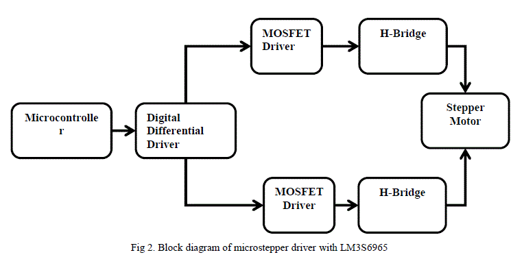 |
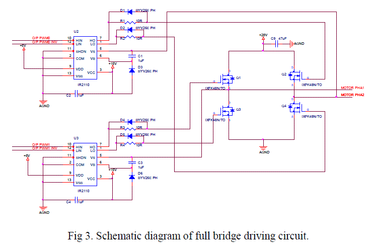
| The LM3S6965 controller-based driver includes two phase bipolar stepper motor STP-MTR-23055(D), 26LS31 differential line driver, IR2110 MOSFET driver, and dual H-bridge. The PWM signals generated are complemented using 26LS31 quad high speed differential line driver. The control signals from differential line driver is fed to IR2110 high and low side MOSFET driver and IR2110 drives the power MOSFET to control the current in the winding. Hbridge circuit contains four MOSFET for each phase of the motor [6]. H-bridge is used for switching the current in the phase of the motor. The driver circuit for the stepper motor for one phase is shown in figure 3. |
 |
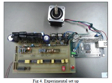
| The experimental set up for driving the two-phase stepper motor using LM3S6965 is shown in figure 4. |
 |
IV. POSITION AND SPEED CONTROL LOGIC |
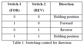
| Stepper motor is controlled by PWM signal. PWM signal can drive the motor to rotate a fixed angle in accordance with the set direction and control the amount of angular displacement by controlling the number of pulses [7]. Number of rotations is proportional to the number of pulses and speed is proportional to the pulse frequency. In the proposed control scheme, three switches, one for speed control and two for direction control are used, which are read by the microcontroller. The forward and reverse directions are achieved by interchanging the PWM signals given to the phase. Constant PWM signal is given to hold the motor. Table 1 shows the switching control for direction. |
 |
| Different speeds are achieved by changing the pulse frequency. In the scheme, the speed is varied by the number of samples taken in one cycle to generate PWM signal. The larger the number of samples, the lesser will be the speed. Sample increment will be different for different speeds, which is controlled by the speed switch. Motor is rotated for a fixed number of rotations in both forward and reverse directions. The number of pulses for one rotation for different speeds is calculated using the following equation. |
| Number of pulses for one rotation = Basic steps per rotation /sample increment x 360 (5) |
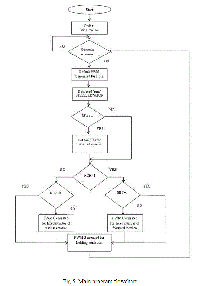
| Figure 5 shows the main program flowchart for speed, direction and position control. Whenever interrupt for PWM generator is obtained, a PWM pulse is generated. The default condition for the motor is holding state. Number of pulses for a specific number of rotations is selected. The speed of the motor is changed by reading the control switch, which changes the sample increment. The direction of the motor is set by reading two control switches. The motor will rotate for a fixed number of rotations in a selected direction and remains in the holding state until the next command is obtained. |
 |
V. CONCLUSION |
| In the present work, microstepping technique, which consists of sine/cosine wave, is used to drive the stepper motor instead of discrete pulses. The microstepper driver based on LM3S6965 is suitable for small and medium microstepper motors as it can achieve high microstepper resolution. Motor controls for specific number of rotations in required direction and speed are achieved by varying the number of pulses and pulse frequency. The experiment showed the smooth running, high precision, rapid response and stability of the system under study. |
References |
|