Keywords
|
| Real time system, CAN protocol, Scheduling, Worst case Response time |
INTRODUCTION
|
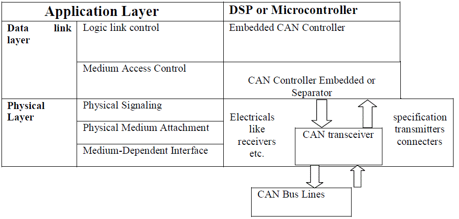
| CAN bus ( controller area network) is a vehicle bus standard planned to permit microcontrollers and tools to communicate with each other inside a vehicle lacking a host computer.CAN(Controller Area Network) bus wire is a message-based protocol, depict specifically for automotive programs but now also used in other areas such as aerospace, maritime, industrial automation and medical component. Development of CAN bus started originally in 1983 at Robert Bosch GmbH.The protocol was officially comesout in 1986 at the Society of Automotive Engineers (SAE) congress in Detroit, Michigan. The first CAN controller chips, produced by Intel and Philips, came on the market in 1987. Bosch published the CAN 2.0 specification in 1991. In 2012 Bosch has specified the improved CAN data link layer protocol, called CAN FD, which will extend the ISO 11898.CAN bus is one of five protocols used in the OBD-II vehicle diagnostics standard [1]. The OBD-II standard has been obligatory for every cars and light trucks sold in the United States since 1996, and the EOBD standard has been obligatory for all petrol vehicles sold in the European Union since 2001 and all diesel vehicles since 2004[1]. The automobile firms have formerly validated the arrival of different electronic control systems that have been evolved in pursuit of protection, ease, impurity prevention, and low cost. These regulate structures, however, presented a disadvantage in that since the transmission data types, needed reliability, etc. varied in the middle of every structures, they were configured in many wire lines, final outcome is grows bus tackle. The following ISO 11898 diagram shows the basic function between CAN bus and ISO-OSI model layers. |
CAN COMMUNICATION PROTOCOL
|
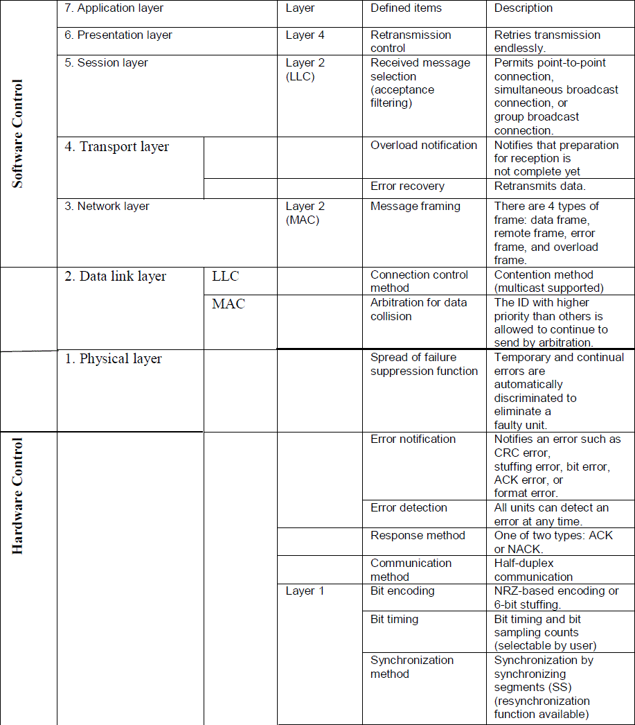
| This CAN protocol include the transport, data link, and physical layers of the primary OSI (Open system interconnection) referral model. Figure 2 shows the defined objects of each layer of the primary OSI referral model in the CAN protocol. Data link layer is divided into MAC (Medium Access Control) and LLC (Logic Link Control) sub-layers, of which the MAC sub-layer compose the nucleus of the CAN protocol. The purpose of the data link layer is to put the waves collect from the physical layer jointly into a relevant message to prepare a process for data communication control such as transmission error control. More specifically, this comprise unite messages into a frame, adjudge data collision, get back ACK, and identify or inform errors [6]. These purposes of the data link layer simply are accomplished in hardware by the CAN controller. The physical layer, the protocol describes the mode in which waves are literally transmitted and the bit timing, bit encoding, and synchronization strategies. However, this does not convey that the waves levels, transmission speeds, sampling nodes senses, driver and wire electrical features, and connector configuration are described specifically through CAN protocol. All of these need to be selected for each structure by the user. At CAN identifications of BOSCH, there are no definitions with respect to the electrical features, etc. of transmitters, receivers and wires. In the ISO standards for the CAN protocol, i.e., ISO11898 and ISO11519-2, however, the electrical features, etc. of transmitters, receivers and buses are defined in every. |
| A. CAN PROTOCOL STANDARDIZED BY ISO |
| The CAN protocol has been standardized by ISO, so that there are many ISO standards for CAN such as ISO11898 and ISO11519-2. In the ISO11898 and ISO11519-2 standards, there is no dissimilarity in definition of the data link layer, but dissimilarity prevails for the physical layer. The CAN transmission protocol, ISO-11898: 2003, describes how data is proceeds in the middle of devices on a lattice and abide by to the Open Systems Interconnection (OSI) model that is described in expression of layers. This inclusion to ISO, the CAN protocol is standardized by industry firms such as SAE*1, as well as by personal foundations and company Table lists CAN base standard specifications. Shows the transmission protocols for automotives categorized by communication speed [12]. |
WORST CASE RESPONSE TIME
|
| The Response time analysis for CAN focus to offer a approach of measuring the worst-case response time of every message. These values can then be measured to the message deadlines to control if the network is schedulable. For structure abide by with the scheduling model [2] the CAN has adhere to enact pre determined priority nonpre- emptive scheduling of messages. Upcoming the inspection in the worst-case response time of a message can be estimated as being made up of three component:(i)one the queuing jitter Jm, communicate to the longest time connecting the start off occurrence and the message being queued, prepared for imparting on the bus,(ii)the queuing waiting Wm , communicate to the longest time that the message can endure in the CAN controller slot or tool driver queue before begin successful transmission on the bus,(iii)the communication time Cm, communicate to the longest duration that the message can take to be transmitted[3-4]. |
The WCRT of message m is given by  |
| The message is said to be schedulable if and only if its worst-case response time is less than or equal to its time limit (Rm ≤ Dm) [5]. The structure is schedulable if and only if all of the messages in the structure are schedulable. The queuing waiting time consist of obstruct Bm, due to bottom prime concern messages which may be in the operation of being communicated when message m is queued and intrusion due to higher prime concern messages which may win interposition and be transmitted in partiality to message m [7-8]. The worst-case queuing waiting for message m occurs for some case of message m queued within a priority level- m busy period that initiates instantly after the longest lower prime concern message begins transmission. Here maximal occupied session begins with a so-called censorious immediate [9-10] where message m is queued concurrently with all higher prime concern messages, and then every of these messages is afterwards queued again after the shortest viable time intervals. In the residue of this paper a occupied duration means this uttermost length busy duration. If more than one case of message m is transmitted during a prime concern level-m busy period, then it is required to control the response time of every case in order to find the overall worst-case response time of the message [12]. Here are some important role we discuss about CAN bus frames. |
CAN BUS FRAME
|
| Data Frame: The work of this data frame is used by the transmit unit to send a message to the receive unit, and is one of the most fundamental frame managed by the user. This data frame contains seven fields.[13] |
| (1) Start of frame (SOF): The work of this field shows the beginning of a data frame. |
| (2) Arbitration field: The work of this field shows the priority of a frame. |
| (3) Control field: The work of this field shows reserved bits and the number of data bytes. |
| (4) Data field: The work of this field is the content of data. Data length in the range 0 to 8 bytes can be transmitted. |
| (5) CRC field: The work of this field is used to find out the frame for a transmission error. |
| (6) ACK field: The work of this field shows a signal for confirmation that the frame has been received normally. |
| (7) End of frame: The work of this field shows the end of a data frame. |
RESULTS & SIMULATION
|
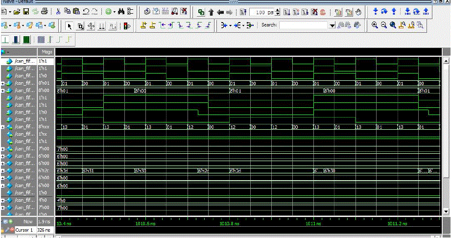
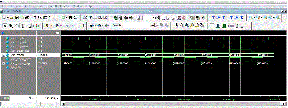
| In this paper we discuss about response time analysis for CAN bus in worst case scenario. The Software simulators are typically used to run Verilog HDL-based designs. The Software simulators sprint on a generic computer or server. We load the Verilog HDL code and simulate the behavior in software We work coding part on Xilinx 14.1version and simulation work done on Modelsim. We work coding on Verilog HDL language. The simulation result shows FIFO (first in first out) data transmission by providing module clock, reset, write, data in, adder, data out and FIFO selected and other simulation result is done by CRC (cyclic redundancy check) by providing module clock, data, enable, initialize and crc. Our main focus to reduce response time by using less clock frequency. |
CONCLUSION
|
| Inside this paper we discuss about response time analysis in worst case scenario by using software Xilinx and Modelsim and Verilog coding for data payloads and transmission of data. This is done by avoiding bit stuffing and it is done by ignoring continuous bits of 0s and 1ns [12].In future there is wide increment use of CAN bus in many fields like in space and in marines. |
ACKNOWLEDGMENT
|
| The correspondence author is thankful to the faculty members of department of Electronics & Communication, IES College of Technology Bhopal, M.P. and India for continuous support and encouragement. Their is a many opportunity available to prove our technical skill for the benefit of social civilization. |
Figures at a glance
|
 |
 |
 |
 |
 |
| Figure 1 |
Figure 2 |
Figure 3 |
Figure 4 |
Figure 5 |
|
References
|
- CAN Specification Version 2.0, Robert Bosch GmbH, Stuttgart, Germany, 1991
- .R. I. Davis, A. Burns, R. J. Bril, and J. J. Lukkien, “Controller area network (CAN) schedulability analysis: refuted, revisited and revised,” Real-Time Systems, vol. 35, no. 3, pp. 239–272, 2007. View at Publisher · View at Google Scholar ·View at Scopus
- K. W. Tin dell, H. Hansson, and A. J. Wellings, “Analyzing real-time communications: controller area network (CAN),” in Proceedings of the 15th IEEE Real-Time Systems Symposium (RTSS '94), pp. 259–263, IEEE Computer Society Press, 1994.
- T. Nolte, H. Hansson, and C. Norstrom, “Minimizing CAN response-time analysis jitter by message manipulation,” in Proceedings of the 8th IEEE Real-Time and Embedded Technology and Applications Symposium (RTAS '02), pp. 197–206, September 2002.
- Daniel Mannisto, Mark Dawson, An Overview of Controller Area Network (CAN) Technology, mBus, 2003.
- Introduction to the Controller Area Network (CAN) SLOA101A–August 2002–Revised July 2008
- K. Tin dell, A. Burns, and A. J. Wellings, “Calculating controller area network (can) message response times,” Control Engineering Practice, vol. 3, no. 8, pp. 1163–1169, 1995. View at Scopus.
- P. Axer, M. Sebastian, and R. Ernst, “Probabilistic response time bound for CAN messages with arbitrary deadlines,” in Proceedings of the Design, Automation & Test in Europe Conference & Exhibition (DATE '12), pp. 1114–1117, Dresden, Germany, March 2012.
- N. Navet, Y. Q. Song, and F. Simonot, “Worst-case deadline failure probability in real-time applications distributed over controller area network,” Journal of Systems Architecture, vol. 46, no. 7, pp. 607–617, 2000. View at Scopus.
- I. Broster, A. Burns, and G. Rodriguez-Navas, “Probabilistic analysis of can with faults,” in Proceedings of the 23rd IEEE Real-Time Systems Symposium (RTSS '02), pp. 269–278, 2002.
- Rajib mall “real time operating system” module 2.(Text book)
- lawrencejenkins,z.c. Alex,gerardineI.mary “Response Time Analysis of Messages in Controller Area Network: A Review” December 2012 hindawi journals article id-148015.2012
- Renesas Electronics website: http://www.renesas.com 1aprail 2010
|