Keywords
|
| ETA, morphological operations, Bounding Box , spatial information , depth map |
INTRODUCTION
|
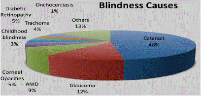
| As per the statistics of the World Health Organization(WHO) in 2013, it was estimated that around 285 million of the population were visually impaired. Among this, 39 million are blind and 246 of them had low vision. Almost majority of the world’s visually impaired people live in developing countries i.e. around 90%. The percentage of people with blindness who are aged 50 and above is about 82%. About 80% of the visual impairment is considered avoidable. Leading causes of blindness and low vision are macular degeneration, diabetic retinopathy, cataract and glaucoma. The Fig.1 describes the causes of Blindness and percentage of prevalence of these diseases in developing countries. |
| The prevalence of visual impairments increases with age i.e. about 15% of the people are in the 45-64, 17% of people in the range 65-74, 26% of the people of age 75 and older. In addition, visual function is comprised of many other components. These include visual field, color perception, stereo acuity , glare recovery, dark adaptation, contrast sensitivity function. These qualities of vision are not commonly assessed in population based visual impairment prevalence studies. Levels of Visual Function include: |
| • 1.- Normal vision |
| • 2.- Moderate visual impairment |
| • 3.- Severe visual impairment |
| • 4.– Blindness |
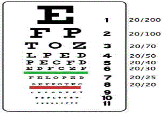
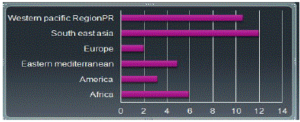
| A Snellen chart given above in Fig. 2 can be used to measure visual acuity. The Fig. 3 shows the distribution of Blind in six WHO regions. |
| 90% of the blind cannot travel independently. 7% use canes whereas 3% could use guide dog but only half of them choose to use guide dog. Perhaps the most widely used device is a Laser Cane which is a regular long cane with built-in laser ranging system. Even with these devices, however the blind traveller has lacked the freedom to travel without assistance, for efficient navigation through unfamiliar environments relies on information that goes beyond the sensing range of these devices. However there are several ETA’s such as NavBelt, RFID, GPS Navigational Aids, GE Navigational Aids, Stereo Vision Systems, Talking Signs System, Zigbee based Navigational Aids, Smart Vision Systems etc. that have been developed to assist the visually impaired along their navigational path. The main objective of this paper is:-Firstly, to assist the visually impaired along their navigation path. Secondly, detecting the obstacles in the ambient space of the environment is one of the most important primary task in designing a collision free autonomous navigation system. The third objective is that, detecting edges in an image which is one of the first and foremost step that has to be performed in order to capture the most significant features of the image. Fourth objective is regarding the perception of depth from a certain environment whose purpose serves to predict or estimate the distance of various objects from the user. Hence depth estimation plays a very important role in such autonomous navigation systems. The goal of the work is an application to assist the visually impaired and blind in indoor as well as in outdoor environments. |
RELATED WORK
|
| In [14], authors modelled a travel aid for the visually impaired based on bat echolocation system. They employed two ultrasonic sensors in a conventional eye glass framework and the spatial information was given to the users by means of audible tones through the earphones. In [13], the system employed a kind of mobile robot obstacle avoidance system which operated in guidance mode as well as in image mode. The user was guided along the predestined path with the recurring beep sound. In [11], an image processing based system was proposed where the relative distance information from the user was obtained through stereo disparity. In [10] , an RFID based blind navigation assistance system was proposed where an RFID reader was incorporated in the cane and RFID tags were laid along the navigational path. In [9], authors proposed a navigation system named “Smart Vision” primarily based on the computer vision module. They used several modules, but it detects only specific landmarks in the environment using Hough Transform. Spatial information of the obstacles and its distance from the user is one of the important aspects in designing a collision avoidance navigation assistance system for the visually impaired. In [2], authors deployed stereo disparity estimation algorithm in order to retrieve the spatial information of the environment by considering the deviation of the estimated disparity of the captured image from that of an ideal system devoid of obstacles. In [4], authors proposed an application to assist the visually impaired based on depth hypothesis which was based on vanishing points. |
SCOPE OF THE PAPER
|
| Detecting the obstacles in the ambient space of the environment is the primary step involved in designing a collision free autonomous navigation system. For this the most optimal edge detection technique along with morphological operations is proposed. Bounding Box technique is further used to create depth map. (minimum row, minimum column and maximum row, maximum column technique) regions of the Bounding Box for depth map creation is being used. Perception of depth from a certain environment is an important feature of human eye that helps in the discernment of the distance of various objects in the environment from the user. Hence depth estimation plays a pivotal role in autonomous navigation systems to know the relationship among the objects in the environment as well as from the user. |
PROPOSED APPROACH FOR INDOOR BASED NAVIGATION
|
A. Block diagram for Indoor based navigation
|
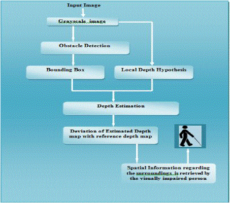
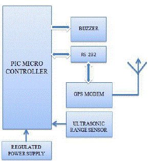
| Firstly to assist the visually impaired along their navigation path the obstacle detection procedure is performed. This basically includes detecting edges as well determining only significant obstacles. Bounding Box technique is used for depth estimation and for determining the deviation of the estimated depth map with the reference depth map which can be conveyed to the visually impaired regarding the spatial information of the obstacles. The overall design of the proposed system is shown in Fig. 4. |
B. Proposed Methodology
|
1) Obstacle Detection:
|
| Detecting the obstacles in the ambient space of the environment is the primary step involved in designing a collision free autonomous navigation system. In order to assist the visually impaired along their navigation path, the obstacles ahead of the user have to be detected and segregated from the background. Firstly to perform obstacle detection , edge detection is really important as it helps to obtain the structural information regarding the boundaries. The main steps in edge detection are: |
| • Smoothing: suppress as much noise as possible, without destroying true edges. |
| • Enhancement: apply differentiation to enhance the quality of edges (i.e., sharpening). |
| • Thresholding: determine which edge pixels should be discarded as noise and which should be retained (i.e., threshold edge magnitude). |
| • Localization: determine the exact edge location. sub-pixel resolution might be required for some applications to estimate the location of an edge to better than the spacing between pixels. |
| The proposed methodology makes use of the best edge detector named canny edge detector and also certain morphological operations such as dilation and erosion for linking broken edges and for noise removal. Although there are several edge detection techniques, the optimal edge detector which is less likely to be fooled by noise is chosen. Because Noise reduction becomes one of the most important challenging aspect of the overall process of obstacle detection , it is very important to choose one of the best edge detector. Canny edge detector makes use of Gaussian filter for noise removal. Canny edge detection working principle: Firstly canny method looks for edges by determining the local maxima of the gradient I. Gradient is calculated using the derivative of Gaussian filter. Further smoothening process is done using the Gaussian filter. Non maxima suppression to the gradient magnitude causes to thin the edges. The canny method uses double Thresholding concept: one to detect the weak edges and the other strong edges. Weak edges are retained only if connected to strong edges. Thus the canny edge method avoids detection of false edges and is less fooled by noise. |
2) Morphological operations:
|
| Morphological operations such as dilation and erosion to link edges as well as to remove noise in the images is being used. Dilation is basically the transformation of an image that can change the size but not the shape of an image. For this purpose , structuring element that can morphologically change the shape is used. Morphological operations probe an image with small shape known as structuring element. The structuring element is known as kernel and it is specified as the coordinates of number of discrete points relative to some origin. It is very important to choose the proper structuring element. Hence the structuring element plays a very significant role in morphological operations. The structuring elements are classified as flat structuring elements and non-flat structuring elements. Most of the times flat structuring elements for real time images is being used. Most of the times disk structuring element merely used for fine adjustments and on the application of square or diamond shaped structuring element the process becomes faster. The method used for decomposing disk structuring element is based on radial decomposition using periodic lines and the method used for performing diamond structuring element is based on logarithm decomposition technique. In this paper, morphological closing operation is used which is usually denoted as A.B where A and B are two binary images. Closing operation is defined as: A.B=(A⊕B)?B. Closing operations offer the benefits like smoothening counters, fuses narrow breaks, eliminating small holes and further fills gaps in counters. Closing operation (dilation followed by erosion) is basically used to compute the morphological gradient of an image. To avoid insignificant obstacles that may exist due to the presence of small close boundaries, the area within the close boundaries is calculated . Further area opening process is being performed. |
3) Bounding Box Technique:
|
| Previously done works were based on Vanishing points to perform depth hypothesis as well as for depth map creation. Problems with vanishing points mainly includes: 1.Three orthogonal vanishing points may not available 2.Hard to accurately determine the vanishing points 3.Accuracy of Vanishing Points affects the accuracy of 3D reconstruction.4. Presence of infinite vanishing points 5. Presence of noise due to reflection and shades may lead to wrong vanishing points. To overcome the drawbacks and difficulties of vanishing points, Bounding Box technique is used to perform the depth hypothesis. Since there is no concept of Vanishing Points in this paper , a default hypothesis with bottom to top depth gradient is being used . Bounding Box is the smallest rectangle enclosing a region. For this initially before computing the Bounding Box , computing the connected components for the binary image by labelling the objects is to be done . This helps to process objects separately. Next measurement of the set of properties for each connected component in a binary image is to done. It helps in computing region descriptors for an image. Bounding Box process: For Bounding Box we need 4 points, one is starting position(x ,y), length and breadth. Minimum value of the row and minimum value of the column – 0.5 gets us the value of the starting position(x, y) of each Box for each obstacle. Maximum value of the column-minimum value of the column+1 is computed to estimate the value of breadth of the box for each obstacle. Further the computation of length of the box is done using: Maximum value of the rowminimum value of the row+1. Bounding Box is applied around each obstacle. |
| 4) Depth Hypothesis and Depth Estimation: Bounding Box technique is further used to create depth map. |
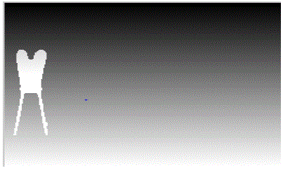
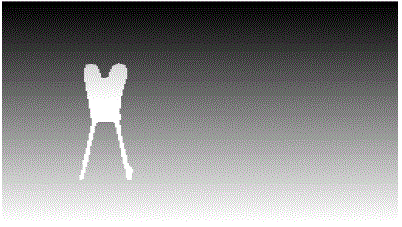
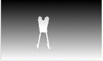
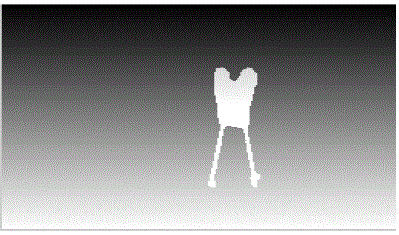
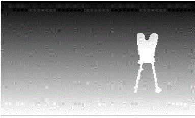
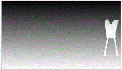
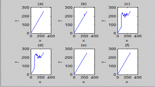
| (minimum row, minimum column and maximum row, maximum column technique) regions of the Bounding Box is being used for depth map creation. Depth hypothesis is done considering two levels of threshold i.e. with colors: white(near obstacles) and gray (far obstacles). Depth Hypothesis is usually expressed in grayscale which states the intensity of closer objects will be more compared to the farther objects. The closer objects are filled with large number of white pixels when compared to farther objects. Lesser the depth , larger will be the intensity values. Finally depth is estimated which is based on local depth hypothesis and regions of the Bounding Box for each obstacle . From the point of view of the user, the navigation path can be considered as a band of pixels that spreads over certain number of columns in the captured image. Each band of pixels spans 8 columns in the captured image. The average over the intensity values along the rows of the depth map of each band is calculated, which gives the deviation of the depth map of the band from the corresponding reference depth hypothesis. Deviation of estimated depth map with reference depth map is used to convey information regarding the spatial environment to the visually impaired along their navigation path. Presence of obstacles results in hike in the intensity values of the depth map in projected 2D space. |
RESULTS OBTAINED FOR INDOOR ENVIRONMENTS
|
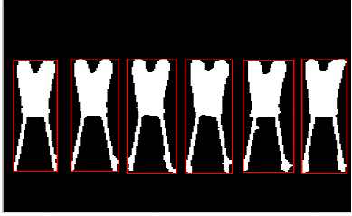
| In the Results shown below, first the captured image (as shown in Fig.5) is converted to grayscale image( as shown in Fig.6) to reduce computational complexity. Next canny edge detection is performed( as shown in Fig.7) which is bound to detect true edges. To perform noise removal and to detect a closely connected object, certain morphological operations are performed which are shown in Fig.8,9 and 10. Further each obstacle is surrounded by Bounding box(as shown in Fig.11) considering the area criteria. Further depth is estimated for each obstacle based on certain coordinates of Bounding Box and depth map is created(as shown in Fig.12,13,14,15,16,17). Next the graph that depicts the deviations of Estimated depth map with reference depth map is plotted as shown in Fig.18. The presence of obstacle distorts the Reference depth map and results in hike in the 2D depth map. |
EXPERIMENTAL DESIGN AND SETUP OF OUTDOOR BASED SYSTEM
|
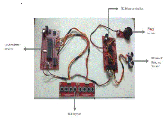
| Through this(as shown in Fig.19 and Fig.20) idea the obstacle detection can be done with the help of ultrasonic ranging sensor. This sensor produces beep sound when it comes in contact with the obstacle. Thus such application of an idea can be used to assist the visually impaired along their navigation path. Further here there are two 4x4 keypad, where each keys represents the navigation path. There is a start key and end key in each of these 4 routes, where the 4 routes correspond to 4 simulation environments. Thus with the help of GPS Simulator modem and Ultrasonic ranging sensor , the visually impaired and the blind can be given navigation assistance and warning in case he/she encounters an obstacle and also in case of deviation. Thus this system can guide the visually impaired along their navigation path by providing Sound assistance to them. |
CONCLUSION AND FUTURE WORK
|
| The proposed approach makes use of canny edge detection in combination with morphological operations for obstacle detection and to extract significant obstacles. Further depth map is constructed using Bounding Box method. The deviation of Estimated depth map with Reference Depth map is used to determine the spatial information of obstacles which can be given to the visually impaired to assist them in their navigation path. Further voice as well as sound based assistance can be given to the visually impaired. GPS Simulator modem also aims to guide the visually impaired if they deviate from their actual navigation path and ultrasonic ranging sensor senses the presence of obstacles and warns the visually impaired when they come in contact with the obstacle . As a future work this paper can be extended to accommodate more depth levels in the creation of depth map by the use of laser cameras or TOF(Time-Of-Flight) cameras with real time image processing capabilities. |
| |
Figures at a glance
|
 |
 |
 |
 |
 |
| Figure 1 |
Figure 2 |
Figure 3 |
Figure 4 |
Figure 5 |
 |
 |
 |
 |
 |
| Figure 6 |
Figure 7 |
Figure 8 |
Figure 9 |
Figure 10 |
 |
 |
 |
 |
 |
| Figure 11 |
Figure 12 |
Figure 13 |
Figure 14 |
Figure 15 |
 |
 |
 |
 |
 |
| Figure 16 |
Figure 17 |
Figure 18 |
Figure 19 |
Figure 20 |
|
| |
References
|
- Kiran G Vetteth, Prithvi Ganesh K, DurbhaSrikar ,” Collision Avoidance Device For Visually Impaired”, International Journal of Scientific& Technology Research Volume 2, ISSUE 10, pp. 185-188,OCTOBER 2013.
- Mohandas, Vimal.,Paily, Roy., Stereo Disparity Estimation Algorithm for Blind Assisting System, CSI Transaction on ICT 1, pp. 3 – 8,2013.
- Abdel IlahNourAlshbatat , “Automated Mobility and Orientation System for Blind or Partially Sighted People”, International Journal OnSmart Sensing and Intelligent Systems Vol. 6, No. 2, pp.568-582, APRIL 2013.
- R. Gnana Praveen*, Roy P Paily , Blind Navigation Assistance for Visually Impaired Based on Local Depth Hypothesis from a Single Image,International Conference on Design and Manufactuing, IConDM, pp. 351-360,2013.
- Paulo Costaa,*, Hugo Fernandesb, Paulo Martinsc, JoãoBarrosod, Leontios J. Hadjileontiadise, Obstacle detection using stereo imaging toassist the navigation of visually impaired people, Proceedings of the 4th International Conference on Software Development for EnhancingAccessibility and Fighting Info-exclusion (DSAI 2012),pp.83-93,2012.
- Dakopoulos, D., Bourbakis, N., Wearable Obstacle Avoidance electronic travel aids for the blind: A Survey, IEEE Transactions on Systems,Man and Cybernetics, Part C: Applications and Reviews 40, pp. 25 – 35,2010.
- Fernandes, H., Costa, P., Filipe, V., Hadjileontiadis, L., Barroso, J., Stereo Vision in Blind Navigation Assistance, World Automation Congress(WAC), 2010.
- Gonzalez, R. C., Woods, R. E., Digital Image Processing, Third Edition. Upper Saddle River, NJ, 2010.
- J.M. Hans du Buf, João Barroso, João M.F. Rodrigues, Hugo Paredes, Miguel Farrajota, Hugo Fernandes, João José, Victor Teixeira, Mário Saleiro, The Smart Vision Navigation Prototype for Blind Users, International Journal of Digital Content Technology and its Applications Vol.5 No.5,pp.351-361, May 2011.
- Ding, Bin., Yuan, Haitao., Jiang, Li., Zang, Xiaoning., The Research on Blind Navigation System Based on RFID, International Conference on Wireless Communications, Networking and Mobile Computing (WiCom),pp. 2058 – 2061, 2007.
- Balakrishnan, G. N. R. Y. S., Sainarayanan, G., A Stereo Image Processing System for Visually Impaired, International Journal of Information and Communication Engineering 2, pp. 136 – 145, 2006.
- Cantoni, V., Lombardi, L., Porta, M., Sicard, N., Vanishing Point Detection: Representation Analysis and New Approaches, 11th International Conference on Image Analysis and Processing, pp.90-94, 2001.
- Shoval, S., Borenstein, J., Koren, Y., The Navbelt - a computerized travel aid for the blind based on mobile robotics technology, IEEE Transactions on Biomedical Engineering 45, pp. 1376 – 1386, 1998.
- Ifukube, T., Sasaki, T., Peng, C., A blind mobility aid modelled after echolocation of bats, IEEE Transactions on Biomedical Engineering 38, pp. 461 – 465, 1991.
- Dr. Boyina.S.Rao, Ms. K.Deepa, Hari Prasanth.L, Vivek.S, Nanda Kumar.S, Rajendhiran.A, Saravana.J ,”Indoor Navigation System for Visually Impaired person using GPS”, International Journal of Advanced Engineering Technology E-ISSN 0976-3945, pp.40-43, 2012.
- Strothotte T., Fritz S.,” Development of dialogue systems for a mobility aid for blind people: initial design and usability testing”, In Proceedings of the Second Annual ACM Conference on Assistive Technologies ,ACM Press, New York, NY, pp.139-144, 1996.
- Sylvain Cardin, Daniel Thalmann and Frederic Vexo, “Wearable Obstacle Detection System for visually impaired People”, Virtual Reality Laboratory (VRlab)CH-1015 Lausanne, Switzerland.
- Alejandro R. Garcia Ramirez, Renato Fonseca Livramento da Silva, Milton Jose Cinelli and Milton Jose Cinelli, “Evaluation of Electronic Haptic Device for Blind and Visually Impaired People”, A Case Study :Journal of Medical and Biological Engineering, 32(6): 423-428.
|