Keywords
|
| 60 GHz, Advanced Design System (ADS), and EVM. |
INTRODUCTION
|
| The 60 GHz frequency band, which provides up to 7 GHz of unlicensed bandwidth, is a highly promising resource for future wireless short-range transmission. 60 GHz is a resonant frequency of oxygen. Oxygen absorbs 60 GHz electromagnetic radiation. The 60 GHz is used for high security communication .The advantage of oxygen absorption is that a 60 GHz signal is quickly reduced to a level that will not interfere with other 60 GHz links operating simultaneously in a close region. This enables easier frequency reuse.Everynew generation of wireless network require more and more cell-sites that are closer and closer together combined with the fast growing demand for the capacity of transmission links.Millimetre wave(MMW)radio has recently attracted a great deal of interest from scientific world, industry, and global standardisation bodies due to a number of attractive features of MMW to provide multi-gigabit transmission rate. Mm-wave is concerned with that part of electromagnetic spectrum between 30 and 300 GHz.This huge bandwidth represents great potential in terms of capacity, andflexibility, making 60 GHz technology particularly attractive for gigabit wireless application.60 GHz regulations allows much higher. transmit power-equivalent isotropic radiated power(EIRP).The higher transmit power is necessary to overcome the higher path loss at 60 GHz while the high path loss seems to be a disadvantage at 60 GHz. It confines the 60 GHz operation to within a room environment.60 GHz systems are designed to provide multi-gigabit data rates with operating range below 20 m to support various applications. Millimetre wave technology is next generation wireless technology that can provide up to multi-Gb/s wireless connectivity for short distance between electronic devices. The data rate is expected to be 40-100 times faster than today wireless LAN technologies. Transmitting entire DVD’S data in roughly 15 seconds.mm Wave is more secure and does not interfere with other wireless technologies. This paper presents the design and simulation of a high data rate wireless communication system operating at 60 GHz.The proposed transmitter architecture in this paper transfers the data rate more than 1Gbps. super heterodyne architecture is popularly used in communication systems and we are taking the advantage of this architecture for our system design and simulation. |
| ,LITERATURE SURVEY |
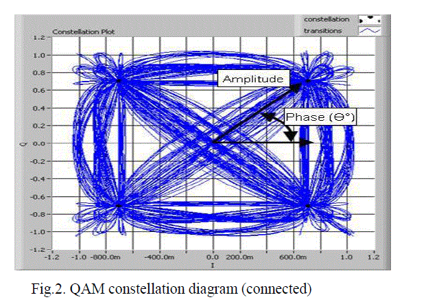
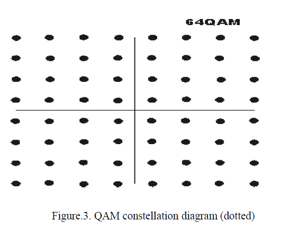
| Researchers recently established a new world record for the highest data rate transmitted wirelessly at 60 GHz, achieving a peak data transfer rate of 15 gigabit/s at a distance of 1 meter, 10 Gigabit/s at a distance of 2 meters and 5gigabit/s at a distance of 5 meters. In addition, high definition video streaming running at 1.485 GB/s has been demonstrated through a one-inch thick wood table. Special efforts have been dedicated to the complete transmitter module implementation operating at a power budget well below the one hundred Pico-joules range. The receiver uses Quadrature amplitude modulation (QAM) that creates four points on a constellation diagram. QAM decodes two bits per symbol. Amplitude shift keying is a form of modulation that represents digital data as a variation in amplitude of a carrier wave. Advantage of QAM is that it is a higher form of modulation. And it is able to carry more bits of information per symbol. Data rate of a link can be increased by selecting a higher order format of QAM. The 60 GHz 1Gbps wireless data-link was designed using FDD and a heterodyne transmitter and receiver. The BER of the data link system for various distances shown by IBM.IBM’s 60 GHz system had1*10-6BER at a distance of 3.5 meters and used a directional antenna of gain 8 dbi .if an ideal transmit power of 27 dBm can be achieved our maximum distance would increase to 8.07 meters. And at half distances of 4.04 meter the BER would be 1.56*10-21 |
ARCHITECTURE AND SYSTEM SPECIFICATIONS
|
| Architecture used in wireless communication transmitter. It is based on the heterodyne process of mixing an incoming signal with an offset frequency local oscillator ( LO) in a nonlinear device to generate an intermediate frequency (IF) signal in the receiver or to produce an RF signal from its IF version in the transmitter. The nonlinear device executing the heterodyne process is called a frequency mixer or frequency converter. In a superheterodyne transmitter, the frequency translation processes may be performed more than once and thus it may have multiple intermediate frequencies and multiple IF blocks |
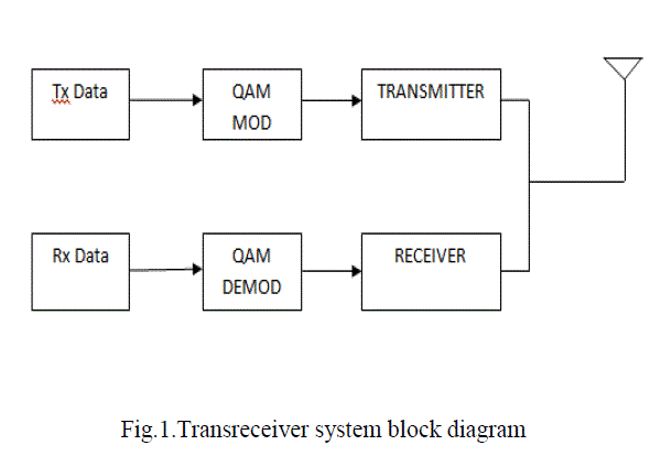
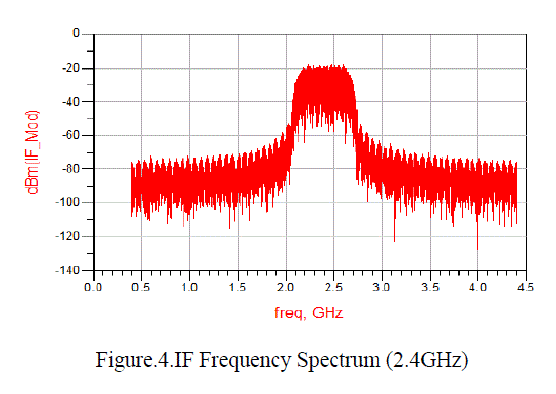
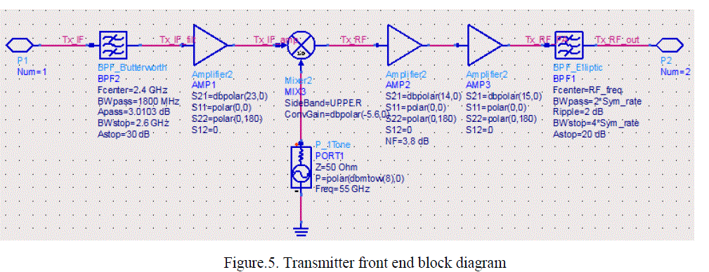
| The transmitter operating at 60GHz uses a QAM modulation scheme for transmitting bits. In the QAM modulation, it has a bandwidth efficiency to transmit two signals and requires coherent demodulation with exact phase and frequency. Because the orthogonal carriers occupy the same frequency band and differ by a 90 degree phase shift, each can be modulated independently, transmitted over the same frequency band, and separated by demodulation at the receiver.QAM is both an analog and digital modulation scheme.it conveys two analog message signals or two digital bit stream by changing the amplitude of two carriers waves using the ASK digital modulation scheme or amplitude modulation analog modulation scheme.QAM is used extremely as a modulation schemes, for digital telecommunication system. The transmitter which has been designed based on superheterodyne architecture, an intermediate frequency of 2.4GHz, a 55GHz frequency is introduced using a LO (local oscillator) is up converted to get the RF frequency and QAM modulation has been used in the transmitter. Chebyshev filter is used at the transmitter side for filtering out the required frequencies. And the PA (power amplifier) is used at the transmitter end to amplify the low power radio frequency tolarge signals of significant power, typically for driving the antenna of the transmitter. |
| EVM (Error Vector Magnitude) measurements are used to evaluate the modulation accuracy of modulators/transmitters. EVM calculation formula |
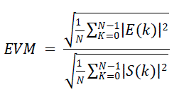 (1) (1) |
| Where |
 |
| N is equal to Symbol Burst and C 0 is a complex constant origin offset (in Volts), C 1 is a unit less complex constant representing the arbitrary phase and output power of the transmitter, and E(k) is the residual vector error on sample S(k) (in Volts). For the above designed transmitter the EVM is 14.5%.The unlicensed band of 60GHz can supports data rates of1Gbps, with a millimetre range. This is suitable for high datarate transfer .To realize a BER of 10-3 at a data rate of 1Gbps,the SNR at input of the demodulator, for QAM is 1.55dB. |
| LINK BUDGET OF THE TRANSMITTER |
CONCLUSION
|
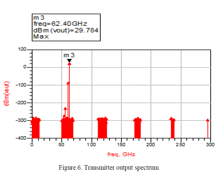
| In this paper, a radio transmitter design at 60GHz has been designed and simulated, using QAM modulation using Agilent ADS software. The system has an output transmitter power of - 4.0 dBm, and EVM of 14.4%. |
ACKNOWLEDGMENT
|
| We take this opportunity to express our deepest gratitudeand appreciation to Mr. K.K. Nayak sir and Mr. Manish Saxena sir who have helped me towards the successful completion of this paper. |
Tables at a glance
|
|
|
Figures at a glance
|
 |
 |
 |
| Figure 1 |
Figure 2 |
Figure 3 |
 |
 |
 |
| Figure 4 |
Figure 5 |
Figure 6 |
|
References
|
- Su-Khiong (SK) Yong.”Introduction to 60 GHz.” 2011 John Wiley & Sons, Ltd.
- Sien Wu, Kareem Graham, Paul Muri, Tom Miller University of Florida, Gainesville. “60 GHz Wireless Link Using Frequency DivisionDuplex QPSK Architecture. FL 3260.
- AzzemiAriffin, Young Chul Lee, Mohd. FadzilAmiruddin, SuhandiBujang, SalizulJaafar and Noor AisyahMohd. Akib, “The First MillimeterwavePoint-to-Point Wireless Gigabit Ethernet Communication System at TMR&D.”Issue 7, Volume 8, July 2009.
- LahatraRakotondrainibe, YvanKokar, Gheorghe Zaharia, and Ghaïs El Zein. “Single Carrier Architecture for High Data Rate Wireless PANCommunications System”IETR-INSA, UMR CNRS 6164, 20, Av. des Buttes de Coësmes, CS 14315, 35043 Rennes Cedex, France.
- Gayan de Alwis / Murray Delahoy. “60 GHz Band Millimetre Wave Technology”. December 2004.
- FengzhongQu, SurendraBoppana and Yao Xie,”Design of a 1Gbps wireless transceiver”11/28/2005.
- Sang-Mm Nam, Jin-Hwa Ku, Yung-KuenOh,Woo-Yong Lee, Ki-Ho Kim,” 60GHz Millimeter-Wave Front-End for Indoor Wireless LAN”
- J. Laskar, S. Pinel, D. Dawn, S. Sarkar, B. Perumana and P. Sen, Georgia Institute of Technology, Atlanta, GA,”The Next Wireless Wave is aMillimetre Wave”.
- S. Reynolds, A. Valdes-Garcia, B. Floyd, T. Beukema, B. Gaucher,D. Liu, N. Hoivik, and B. Orner, “Second generation 60-ghz transceiver chipset supporting multiple modulations at gb/s data rates (invited),”in Bipolar/BiCMOS Circuits and Technology Meeting, 2007. BCTM ’07.IEEE, 30 2007-oct.2 2007, pp. 192-197.
|