A power system is becoming more complex and heavily loaded day by day. Earlier electric power systems were small and localized. Thus, Real and reactive power compensation in transmission line is essential which will improve the stability of ac system. Flexible Alternating Current Transmission System (FACTS) technology provides new opportunity to control the power and enhancing the capacity of the present as well as new lines. The Static Synchronous Series Compensator (SSSC) is newer generation of FACTS device which enables control of active and reactive power and enhancement of power transfer capability of transmission line. This paper describes theory and modelling technique of SSSC using multi level (Three) inverter with Sinusoidal Pulse Width Modulation technique and dq0 transformation using MATLAB Simulink.
Keywords |
| FACTS, Inverter, Matlab/Simulink, Pulse width modulation, Real and Reactive power, SSSC. |
INTRODUCTION |
| Electricity demand has been increased since last few decades. Today’s power system is interconnected and highly
complex. Electric power flow through an alternating current transmission system is the function of the line impedances,
the magnitudes of sending end and receiving end voltages and phase angle between these voltages. [1] According to
IEEE the FACTS can be defined as, “Alternating current transmission systems consisting of power electronics based
and other controllers to enhance controllability and available power transfer capability (APTC) controllers which can
provide limit on one or more AC transmission system parameters like voltage, current and powers. By using FACTS
devices the line parameters can be changed and power flow along transmission lines could be controlled. The devices
under the FACTS are capable of fast responses and thus could be used for multiple applications. [2-4] |
LITERATURE SURVEY |
| Mr. D.M. Tagare [1] has discussed the working of Static Synchronous Series Compensator thoroughly. Flexibility
through fixed series capacitor and devices based on voltage source inverter are explained. The responses of SSSC for
different contingencies have been studied. N.G. Hingorani and L Gyugyi [2] have been deeply involved in pioneering
work in this new FACTS technology. Hingorani pioneered the concept from EPRI and Gyugi invented several key
FACTS controllers. Both the authors provides all the basic idea of FACTS to power engineers, it also differentiates the
state of transmission line before and after evolution of FACTS controllers. R. Mohan Mathur and Rajiv K. Verma [3]
explain the system before and after evolution of FACTS. The necessity, advantages and controller over the traditional
or conventional system is proposed. Sen K.K. [4] has developed model of Static Synchronous Series Compensator
(SSSC) using Electromagnetic Transient Program (ETAP) simulation package, with pulse width modulation (PWM)
technique. 48 pulse PWM inverter is used for the simulation. M.H. Rashid [5] has discussed about all the basics of
inverters along with controlling strategies. M. Faridi, H. Maeiat and P. Farhadi [6] has developed SSSC model
equipped with a source of energy in the DC link which can supply or absorb the reactive and active power to or from
the line. Simulations have been done in MATLAB/SIMULINK environment. P. Suman, N. Vijaysimha and C.B.
Saravanan [7] have developed the schematic and basic controls of a reconfigurable FACTS system that can be used to
realize the major voltage source converter FACTS topologies: STATCOM, SSSC and UPFC. A Digital Signal
Processor (DSP) is used to implement the control system for these devices. A 24 pulse GTO converter is used for the
simulation model. L. Surindam Kumar, Arindam Ghosh [8] and Fawzi A. L. Jowder [9] have discussed about
modelling, control design and different modes of SSSC. |
THEOROTICAL CONCEPT |
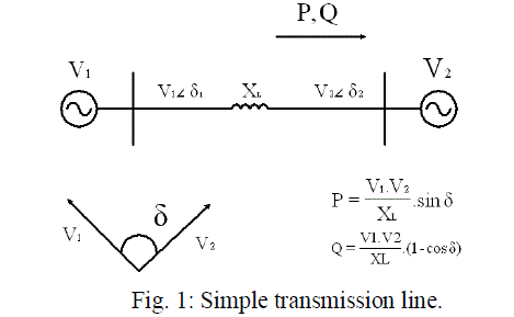 |
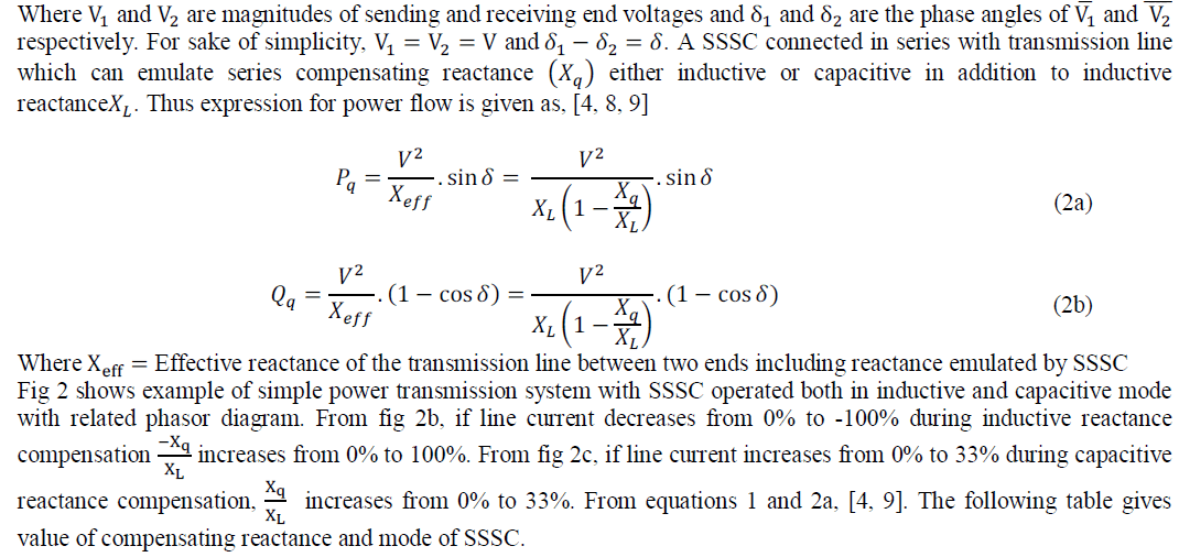
| Fig. 1 shows single line diagram of simple transmission system with an inductive reactance XL connecting in between
sending end voltage |V1 | and a receiving end voltage source is |V2| respectively. The real and reactive power flow at the
receiving end voltage source is given by, |
 |
 |
 |
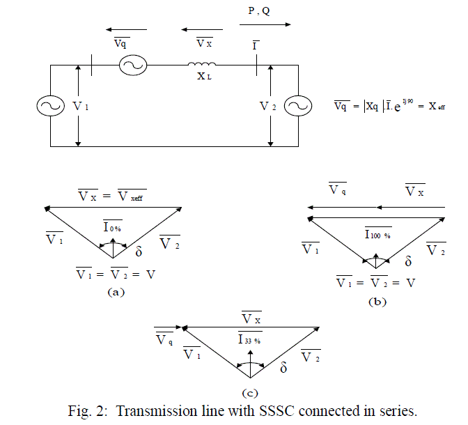 |
| (a) Normal mode of operation. (b) Inductive mode of operation. (c) Capacitive mode of operation. |
 |
RESULT AND DISCUSSION |
A. Two machine power systems |
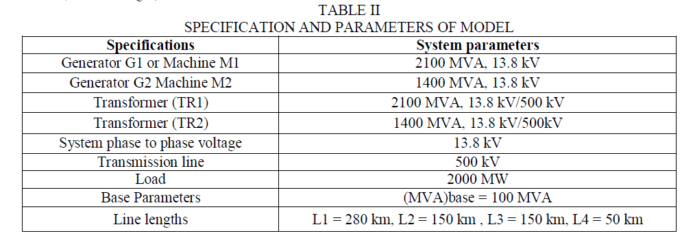
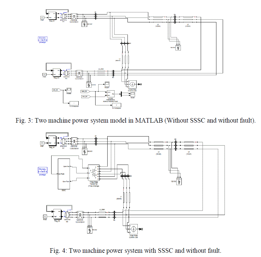
| The test system (shown in fig. 3) consists of two machine power system which essentially consisting of two power
generation plants. The specifications of model are as shown in table no. 1. The actual SSSC is connected between bus
B1 and B2. (Shown in fig.4) |
 |
 |
| B. Control System: |
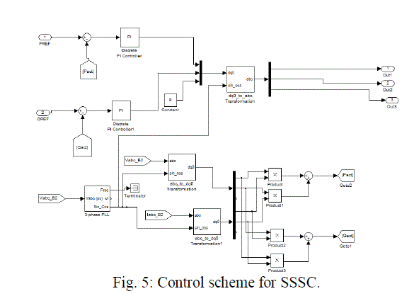
| In this control scheme, (Refer the fig. 5) Pref is taken as 4pu and Qref is taken as -1 pu is taken. The instantaneous
power is obtained in terms of d-q quantities of voltages and currents as below, |
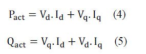 |
| The voltage and current of bus-2 in dq0 references are used to find out active and reactive powers of bus-2 and are
compared with the determined reference values and thus error signal is produced which is further given to the PI
controllers. By adjusting parameters of the PI controllers, our goal is to achieve the zero signal error. Then, the output
of the controllers are converted to the abc frame of reference and given to the SPWM. In SPWM, the reference wave is
sinusoidal wave and carrier wave is triangular wave. [5, 8] |
 |
| C. Different cases and Results: |
| Two machine systems with four buses configuration have been simulated in the MATLAB / SIMULINK software. We
are getting the results at bus 2 as SSSC is connected at bus 2. Results after simulation are given in following table. |
 |
| Case I: Bus 2 parameters without SSSC without fault: |
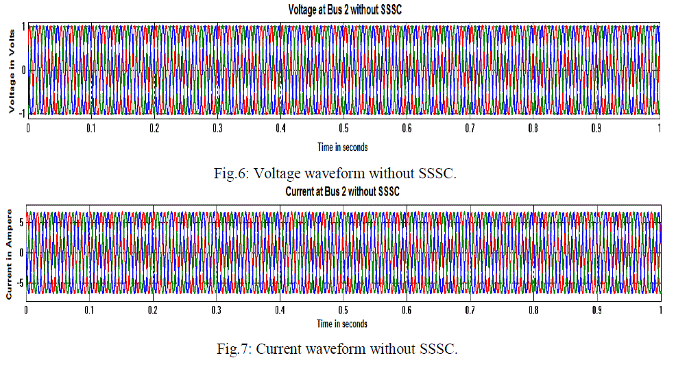 |
| Fig. 6 and 7 shows Voltage and current waveforms without connection of SSSC and without occurrence of fault on
transmission line. All the three phases of voltages and currents are shown clearly. Both current and voltages are
expressed in terms of per unit quantities. |
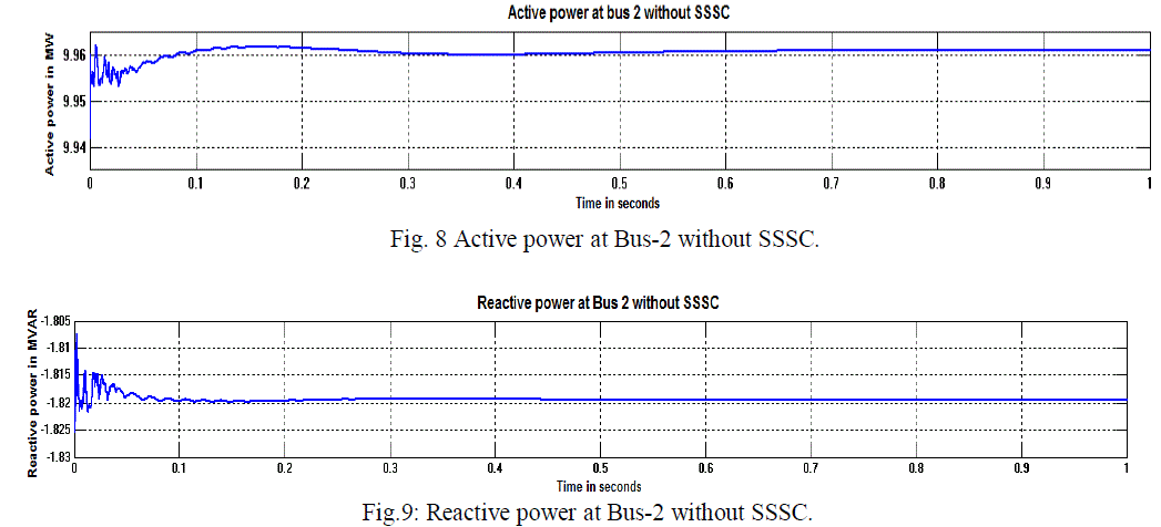 |
| Fig.8 and 9 shows the active and reactive power at bus 2 oscillates due to presence of large loads in the system. This
condition continues till the 0.9 to 1.0 cycles. There are various stabilizing devices such as governor, PSS that can be
used for damping out oscillations. Amplitude of oscillation is more in case of active power than reactive power.
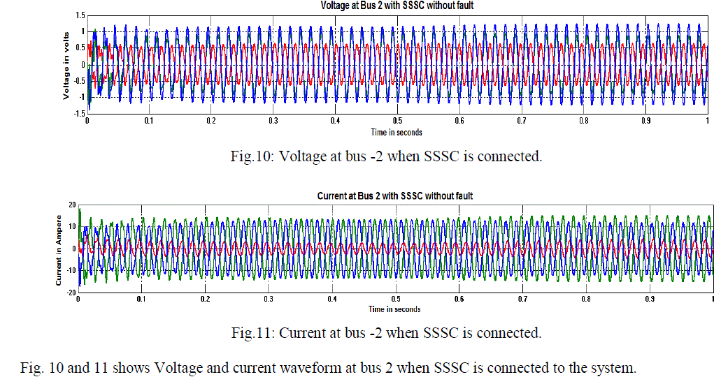
Voltage and current waveforms are shown in fig. 6 and 7 which are relatively same as that of sinusoidal waveforms.
The voltage amplitude is near to 1 pu and current amplitude is near about 6.40 pu. |
| Case II: Bus-2 parameters with SSSC without fault: |
 |
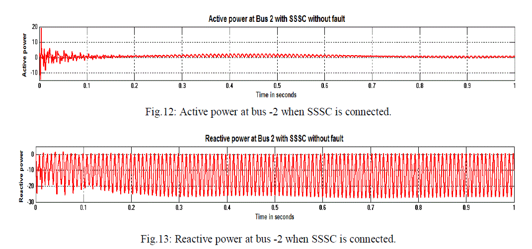 |
| Fig. 12 and 13 shows active and reactive power at bus 2 when SSSC is connected. Whenever SSSC is connected to the
system, active power damping time will get reduced than that of the mode without SSSC. In case of without SSSC
damping time was near about 1 cycle or sec. whereas in case of SSSC mode, time is 0.8 to 0.85 cycles. After
connecting SSSC, controlling the power flow at bus-2, we want to keep the constant voltage 1 pu. |
| Case III: Bus-2 parameters without SSSC with fault: |
| Here, three phase fault is occurring at bus and system performance is checked without SSSC. Ground resistance used is
1.66 ohm and transition time is [0.15 0.2] |
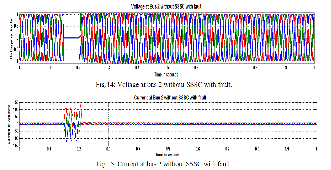 |
| Fig. 14 and 15 shows voltage and current at bus 2 without SSSC but with fault. Three phase fault has been occurred on
transmission system. Fault can make disturbances in the system for a greater time. Fault occurs at 0.15 to 0.2 cycles. |
| The voltage reduces to zero during fault period and at the same time magnitude of current is high as compared to
healthy condition. |
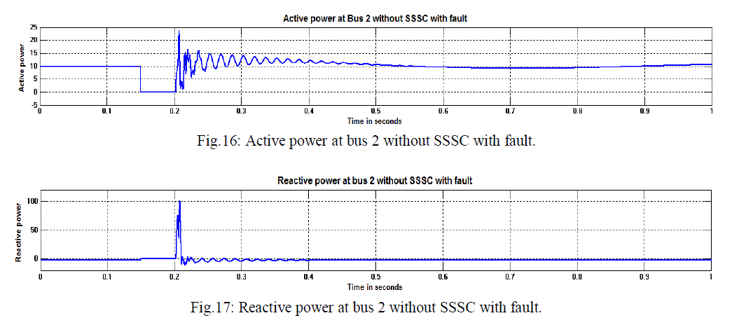 |
| From fig. 16 and 17, during the period of occurrence of fault, active power drastically reduces to zero. Fault is cleared
at 0.2 seconds. As soon as the fault is clear, Active power starts increasing and it damp out nearly 0.9 to 1.0 cycles.
While during fault, reactive power increases and as fault is cleared it reduces to zero or even at negative value. The
time required to damp out the oscillation is near about 0.4 to 0.5 seconds. |
| Case IV: Bus-2 parameters with SSSC with fault: |
| In this case, three phase fault occurs on the line. Transition time is [0.15 0.2] and system performance is checked in the
presence of SSSC. |
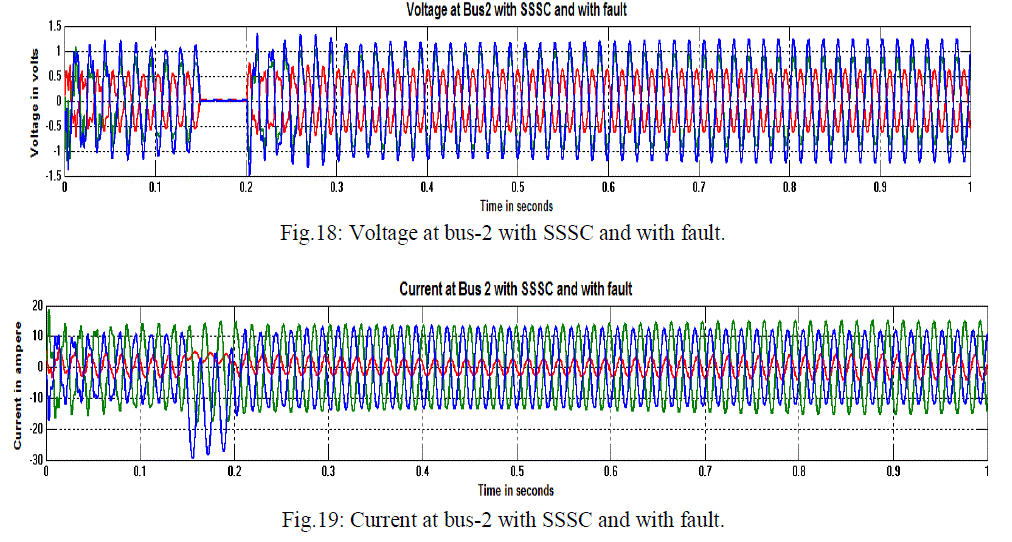 |
| Fig.18 and 19 shows voltage and current of bus 2 when SSSC in connected and three phase fault occurs on the
transmission line. Transition time for the fault is [0.15 0.2]. During fault period, voltage waveform drastically reduces
to zero while current waveform increases. |
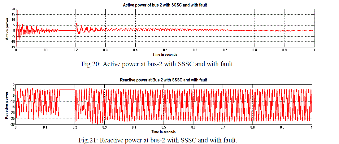 |
| Fig. 20 and 21 shows Active and reactive power at bus 2 with SSSC and with fault. As the fault occurs between 0.15 to
0.2 seconds, the active power reduces to zero for that period. As fault is cleared at 0.2 seconds, active power begins to
increase. The oscillations get damp out nearly at 0.8 to 0.85 seconds whereas in case reactive power, power reduces to
zero during fault period and after clearing the fault it becomes negative and even increases towards negative side. |
CONCLUSION |
| The onset of series connected FACTS controller like SSSC has made it possible not only to regulate power flow in
critical lines. SSSC has reactive voltage control which can inject controllable reactive voltage in quadrature with the
line current, emulating either inductive or capacitive reactance in series with transmission line. In this paper, the
operation of SSSC model is verified by connecting it in series with the transmission line. SSSC has been studied on two
machine power system and connected at bus-2. Thus from this paper, SSSC can be effectively used to damp out power
oscillations on power transmission system with and without fault. It can also able to control power flow at particular or
desired point. The application of the SSSC can be expanded in future for complex and multi-machine system to
mitigate the problem of power oscillation in power systems. |
References |
- D.M. Tagare, âÃâ¬ÃÅReactive power managementâÃâ¬ÃÂ, Tata Mc-graw hill company, New Delhi, India, 2004, pp: 434-456.
- N.G. Hingorani and L Gyugyi, âÃâ¬ÃÅUnderstanding FACTS: Concepts and technology of Flexible AC transmission systemâÃâ¬ÃÂ, IEEE Inc. New York,USA, 0-7803-3455-8.
- R. Mohan Mathur and Rajiv K. Verma, âÃâ¬ÃÅThyristor âÃâ¬Ãâ based controllers for electrical transmission systemsâÃâ¬ÃÂ, Willey publication, New York,USA, 2002, pp: 1-13.
- Sen, K.K., "SSSC-static synchronous series compensator: theory, modeling, and application," Power Delivery, IEEE Transactions on, vol.13,no.1, pp.241-246, Jan 1998.
- M. H. Rashid, âÃâ¬ÃÅPower electronics âÃâ¬Ãâ circuits, devices and applicationsâÃâ¬ÃÂ, prentice hall, Englewood Cliffs, New Jersey.07632, 1988.
- Faridi, M.; Maeiiat, H.; Karimi, M.; Farhadi, P.; Mosleh, H., "Power system stability enhancement using static synchronous seriescompensator (SSSC)," Computer Research and Development (ICCRD), 2011 3rd International Conference on , vol.3, no., pp.387,391, 11-13March 2011.
- P. Suman, N. Vijaysimha and C.B. Saravanan, âÃâ¬ÃÅStatic synchronous series compensator for series compensation of EHV transmission lineâÃâ¬ÃÂIJAREEIE, Vol. 2, Issue 7, pp: 3180-3190, July 2013.
- Sunil Kumar, L.; Ghosh, A., "Modeling and control design of a static synchronous series compensator," Power Delivery, IEEE Transactionson, vol.14, no.4, pp.1448 -1453, Oct 1999.
- Jowder, F.A.L., "Influence of mode of operation of the SSSC on the small disturbance and transient stability of a radial power system," Power Systems, IEEE Transactions on, vol.20, no.2, pp.935, 942, May 2005.
|