International Journal of Advanced Research in Electrical, Electronics and Instrumentation Engineering
ISSN ONLINE(2278-8875) PRINT (2320-3765)
ISSN ONLINE(2278-8875) PRINT (2320-3765)
Aswani Rajan1 and Asha Anu Kurian2
|
| Related article at Pubmed, Scholar Google |
Visit for more related articles at International Journal of Advanced Research in Electrical, Electronics and Instrumentation Engineering
Demand for renewable energy sources is increasing due to shortage of power as well as environmental concerns. In this paper, a wind - PV generating system connected to the grid . Since wind and PV are complementary in nature, continuous power availability can be obtained. The main issue regarding grid integration of distributed generation is power quality, harmonics etc. In the proposed system the fuzzy control circuit will perform the function of harmonic elimination, so that the need for an APF(Active Power Filter) does not arise. The system is modeled and analysed using MATLAB Simulink. The new system will result in high reliability, low cost and better utilization of resources available.
Keywords |
| PV array, Single stage inverter, Switched inductornBuck Boost converter (SIBBC), Maximum Power poin Tracking (MPPT), Incremental conductance algorithm. |
INTRODUCTION |
| Day by day energy requirements are increasing and electrical utility is concerned about meeting the growing energy demand. Almost 70 percent of the energy requirements are satisfied by fossil fuels. Since they are on the path of extinction and it is associated with air pollution, global warming and increase in cost, it has become necessary to utilise renewable sources for satisfying our energy requirements. Renewable resources are free of cost and they are abundantly present in nature. So we can utilise them for generating electrical energy. |
| Renewable energy sources such as solar energy, wind energy, biomass etc. can be used for meeting the energy demands. Due to the intermittent nature of the renewable energy sources, the reliability cannot be maintained. So combination of renewable energy sources such as wind and PV will provide a solution for the discontinuity problem. Generally PV and wind are complementary in nature, since sunny days are calm and strong wind occurs on cloudy days or in night time[1]. Therefore by using a wind-PV generating system will result in availability of continuous power than with individual sources. This will results in less carbon emission and reduce global warming etc. |
| Interconnection of renewable energy source will affect the system stability, voltage regulation and cause serious power quality problems. Therefore efficient technical and regulatory frame work should be there to ensure safety, reliability, and efficient operation. Also increasing use of non-linear load results in serious problems of harmonics. The oscillation produced due to harmonics will lead to mechanical stresses and malfunction of sensitive equipments. |
 |
| Active power filters are usually employed to solve the power quality problems [2]. In this paper, a wind-PV generating system is connected to grid and the PQ is maintained without using APF(Active Power filter) [3].There are different ways by which PQ can be maintained [4] [5]. Here, two independent controllers have been designed for DG interface and that controllers will perform the function of active power filtering (eliminating harmonics)[6], thereby increasing efficiency, reliability and quality. |
 |
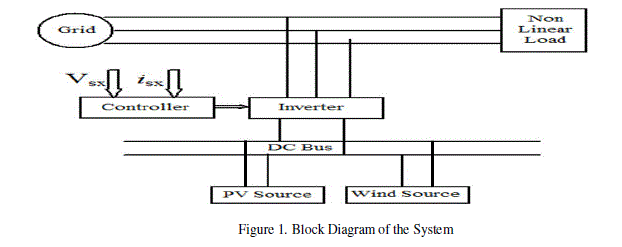
SYSTEM DESCRIPTION |
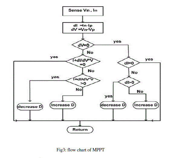
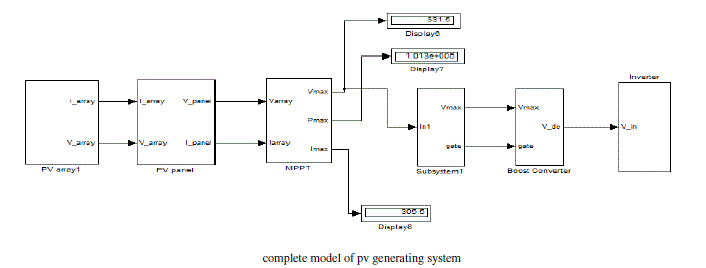
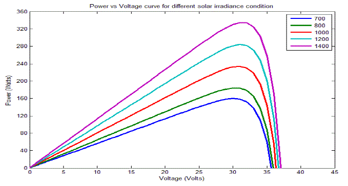
| The system considered in this paper consist of two renewable energy sources, a photovoltaic source of 100KW and a wind generating system of 10KW Solar cell is basically a p-n junction fabricated in a thin wafer or layer of semiconductor. The electromagnetic radiation of solar energy can be directly converted to electricity through photovoltaic effect. The solar panel generates low level dc voltages (generally between 12 and 68 volts), depending on the technology used in the panel construction. The input required for almost all electrical equipments is single phase or three phase ac. Therefore power interfacing or power conditioning devices are necessary to connect the electrical equipments to the solar panel. The power conditioning devices includes a dc-dc boost converter and an inverter with control circuits. A dc-dc boost converter is used to increase the dc voltage level to obtain required output voltage. After boost conversion, an inverter is required to convert dc-ac. The switching frequencies are selected in such a way that there should be compromise between the switching losses and output filter size. In this chapter the modelling of PV generating system with the changes in solar irradiation level and temperature is explained. The MPPT (Maximum Power Point Tracking) is done using incremental conductance algorithm. A photovoltaic panel is a device which converts luminous energy into electrical energy. |
| The solar panel generates low level DC voltages (generally between 12 and 68 volts), depending on the technology used in the panel construction. The input required for almost all electrical equipments is single phase or three phase AC. Therefore power interfacing or power conditioning devices are necessary to connect the electrical equipments to the solar panel.The power conditioning devices includes, a DC-DC boost converter and an inverter with control circuits. A DC-DC boost converter is used to increase the dc voltage level to obtain required output voltage. After boost conversion, an inverter is required to convert DC-AC. The switching frequencies are selected in such a way that there should be compromise between the switching losses and output filter size. |
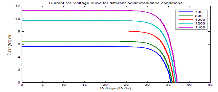
| There are different methods to model PV systems, by using the current equation [7], or by using voltage equation [8]. The output of the PV array varies according to changes in atmospheric condition. So the effect of those changes should be incorporated in the model. In this paper the current equation is used to model the PV system. |
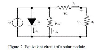
| The solar module is a non-linear device and can be represented as a current source model, as shown in Fig.2.Where Rsh ,Rs, Ro represents internal shunt resistance,the internal series resistance and the output resistance respectively, Io is the output current, Id is the diode current, Irsh is the current due to intrinsic shunt resistance of the solar module and Vo is the output voltage of the panel. The traditional I-V characteristic of a solar array is given by |
 |
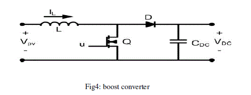 |
| V mode and by applying volt sec balance, the equation for boost converter gain is expressed as in (2) . |
2.1. Wind Generating System |
| The wind generating system used in this paper is shown in Fig.5. It consist of a wind turbine coupled to a permanent magnet synchronous generator. The output of the wind generating system is fluctuating in nature due to uncertain nature of the wind and variation in wind speed. So in order to make the voltage constant an uncontrolled diode rectifier unit and a boost converter is used. The boost converter in wind energy conversion system is used here is to make constant dc output voltage by varying the duty ratio. |
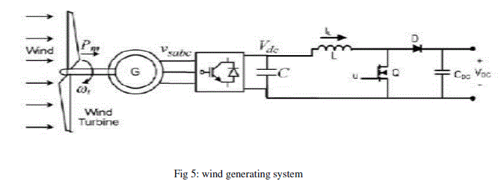 |
| where, Pw is the power extracted from the wind, ρ is the air density, which is equal to 1.22 kg/m3 at sea level at temperature T = 288K, Cp is the power coefficient, Vw is the wind speed in m/s, A is the area swept by the rotor,τw is the amount of aerodynamic torque and ωw is the turbine rotor speed. |
CONTROLLER |
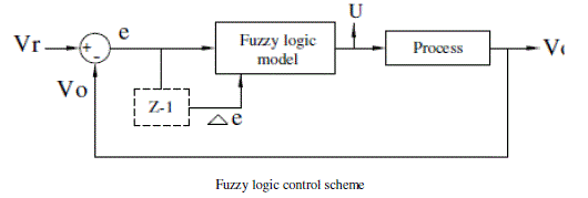
| The conventional PI controllers are fixed-gain feedback controllers. Therefore they cannot compensate the parameter variations in the process and cannot adapt changes in the environment. PIcontrolled system is less responsive to real and relatively fast alterations in state and so the system will be slower to reach the set point. On the other hand P&O method for MPPT tracking will not respond quickly to rapid changes in temperature or irradiance. Therefore the fuzzy control algorithm is capable of improving the tracking performance as compared with the classical methods for both linear and nonlinear loads. Also, fuzzy logic is appropriate for nonlinear control because it does not use complex mathematical equation. The two FLC input variables are the error E and change of error _E. The behavior of a FLC depends on the shape of membership functions of the rule base. In this paper a fuzzy logic control scheme (Fig.5) is proposed for maximum solar power tracking of the PV array with an inverter for supplying isolated loads. They have advantages to be robust and relatively simple to design since they do not require the knowledge of the exact model. On the other hand the designer needs complete knowledge of the hybrid system operation. |
| 3.1. Fuzzification |
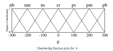
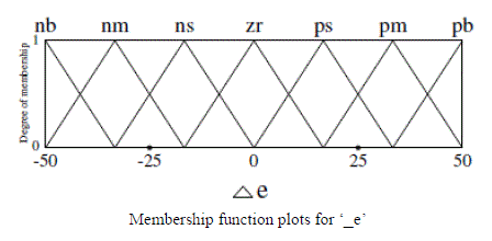
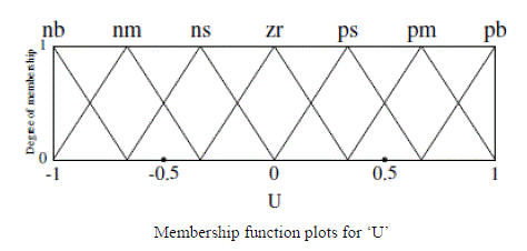
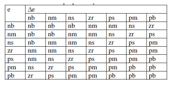
| The membership function values are assigned to the linguistic variables using seven fuzzy subset called negative big (nb), negative medium (nm), negative small (ns), zero(zr), positive small (ps), positive medium (pm), positive big (pb). Fuzzy associative memory for the proposed system is given in Table-2. Variable e and _e are selected as the input variables, where e is the error between the reference voltage (Vr) and actual voltage (Vo) of the system, Δe is the change in error in the sampling interval. The output variable is the reference signal for PWM generator U. Triangular membership functions are selected for all these process. The range of each membership function is decided by the previous knowledge of the proposed scheme parameters. |
| 3.2 Inference engine |
| Inference engine mainly consist of Fuzzy rule base and fuzzy implication sub blocks. The inputs are now fuzzified are fed to the inference engine and the rule base is then applied. The output fuzzy set are then identified using fuzzy implication method. Here we are using MINMAX fuzzy implication method. |
 |
 |
 |
 |
 |
| 3.3 Defuzzification |
| Once fuzzification is over, output fuzzy range is located. Since at this stage a non-fuzzy value of control is available a defuzzification stage is needed. Centroid defuzzification method [13] is used for defuzzification in the proposed scheme. |
RESULTS |
 |
 |
 |
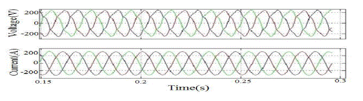 |
| source voltage and current waveform |
CONCLUSION |
| The modeling of wind PV generating system is done and its power quality is analysed using different controllers. Two different controllers have been used. The first one is a PI controller and the second one is repetitive controller. From the THD (which is a measure of power quality) analysis report obtained in both cases, it is observed that the fuzzy controller have better performance over PI controller. The advantage of the system is that it will eliminate the need for APF. The reliability can be maintained. No need of additional cost for an APF. Therefore the system with fuzzy controller is an efficient power quality compensator for grid connected Wind PV generating system. |
References |
|