Research & Reviews: Journal of Engineering and Technology
ISSN: 2319-9873
ISSN: 2319-9873
Received date: 14/01/2019; Accepted date: 04/02/2019; Published date: 08/02/2019
Visit for more related articles at Research & Reviews: Journal of Engineering and Technology
Power quality is a measure of electrical power efficiency which is transmitted from the point of generation to the consumers. Power quality is a set of parameters like continuity of supply and characteristics of voltages such as magnitude, frequency, symmetry and waveform. Currently, power quality is a problem that leads to financial issues. Many surveys have been shown that poor power quality causes large economic losses to industrial sectors and large amount of power is wasted due to power quality problems like sags, swells, harmonics, flickers etc. In this paper, the modeling and simulation of a Dynamic Voltage Restorer (DVR) is achieved using MATLAB/Simulink. Faults are created with the proposed systems, and the disturbances are initiated at duration of 0.8 sec till 0.95 sec. Comparison of the performances of the Fuzzy neural and Fuzzy logic based DVR are presented. Results are showed that Fuzzy logic controller is able to restore the load voltage to the nominal value in both linear and nonlinear loads quickly and efficiently. But when the 2nd and 3rd harmonics are superimposed on the voltage sag and voltage swell by the application of 3-ph programmable source, the fuzzy logic controller fails to restore and reduce the harmonic content to acceptable values which is according to IEEE standard 3% for the individual voltage and 5% for the three phase voltage. While the Fuzzy neural controller has been very powerful and efficient to restore the load voltage to the pre-sag value and make it smooth under different cases of faults and nonlinear load conditions and keep the harmonics within the permissible limits in all cases.
Power quality, Fuzzy logic, Fuzzy neural, Controller, Sag, Swell
The electric power distribution system has huge networks with a large number of sources and loads are connected through a widespread distribution lines. Particularly the distribution systems have a large number of non-linear loads which affect the quality of power supplies. The smoothness of the waveform is lost due to non-linear loads, which cause many power quality problems. But the actual view of customers is to get the best quality of power and reliability of power supplies of the load centers in the area where they are located [1]. The reason for demanding high quality power during production process is mainly because of the modern manufacturing that operates at high efficiency requires stable and trouble free power supply for the successful operation of their machines [2]. Actually the users of power systems should be supplied with a continuous flow of energy with defect free sinusoidal voltage at the promised magnitude level and frequency. The inability to provide the required quality of power output may sometimes cause complete shutdown of the industries. The power electronic devices like adjustable speed drives, automation devices, computers and UP, etc are very sensitive to voltage disturbances such as, voltage sags, swells and harmonics [3]. Poor power quality may lead to failing or malfunctioning of the sensitive equipment, resulting in production and financial loss, also putting life at risk where safety is priority. Voltage sag and harmonics are the most common power quality problems in industrial, service and transparent sectors. Sag is a sudden decrease in the rms voltage and makes it between 10% and 90% from its nominal value, and lasting from 0.5 cycles to several seconds. Sag can be symmetrical or unsymmetrical, a three phase fault produce symmetrical sags. Single line to ground fault and double line to ground fault causes unsymmetrical sag. Harmonics is the presence of spectral components whose frequencies are multiplies the fundamental frequency. The harmonics occur due to non-linear load such as power electronics components and induction motors. According to the IEEE standards for the system of less than 69 kV the harmonic distortion limits are 3% for individual voltage and 5% for total harmonic distortion. Harmonics cause overheating, overloading and additional losses to the transformers, motors and other power system equipment [4]. A Swell is a sudden increase in the rms voltage and makes it between 110% and 190% from nominal value, and lasting from 0.5 cycles to several seconds. The main reason for the swell is turn on the large capacitive loads or shutdown a large inductive load. The voltage interruption is decreased the voltage to less than 10% from its nominal value for a period not exceeding 1 min. To solution the power quality problems there are different methods such as: APF (Active Power Filter), DSTATCOM (Distribution Static Synchronous Compensator), Dynamic Voltage Restorer (DVR), SVC (Static Var Compensator), BESS (Battery Energy Storage System), TSC (Thyristor Switched Capacitor), UPS (Uninterrupted Power System). DVR is one of the most efficient and reliable solutions due to its lower cost, smaller size and dynamic response, and DVR is effective to restore the load voltage to the nominal value and make it regular under all cases of faults and non-linear conditions. DVR is able to compensate the voltage disturbances by adding or subtracting appropriate voltages in series with the supply voltage and load point and thereby prevent unreliability power supply. Normally in steady-state operation DVR is not going to absorb/inject real power. But whenever voltage sag/swell or unbalance in supply voltage occurs in the system it will come into picture and supports the power system by injecting/ absorbing real power instantly from D.C. link. This aim can be best achieved if the DVR is controlled by an appropriate modern control strategy. For improve the performance of the (DVR) several studies have been conducted these studies are shown that, a Phase Advanced Compensation strategy for DVR was used where a closed loop controller that consists of an outer voltage loop and two inner current loop was proposed in control system of the DVR And the studies are shown that the aritificial intelligent controller for the DVR is effective and powerful in eliminating of power quality problems because that the DVR is non-linear in nature and needs a non-linear controller. The MATLAB/simulink is demonstrated that the capability of DVR based on Fuzzy Neural is more efficient and effective in mitigating the power quality problems, also In general, there are no standard method for transforming human knowledge to the rules base of the fuzzy inference system. The selection of the type, size and parameters of the membership functions has been achieved by trial and error; therefore there is a real need to an effective method of tuning the input and output membership functions and reducing the rules to the minimum rules. The ANFIS method was developed to overcome the difficulties mentioned previously.
DVR Essentially as Shown in Figure 1 consists of Power Circuit

Figure 1: The basic configuration of the DVR.
• Energy storage unit which can be Battery Energy Storage System [5], super capacitor [6], flywheel energy storage [7], wind energy [8], photo voltaic [9]. In this work Battery Energy Storage System (BESS) was used because of the high stability for the (BESS)
• Inverter circuit: In this work the Three-Phase three-Level Inverter is used to converts the DC voltage from the (Battery Energy Storage System) to a controllable three-phase AC voltage, which is equal to the compensating voltage because of high power and low harmonics at the output of this inverter. The structure of the three level single phase inverter and three-Phase three levels inverter are shown in Figures 2 and 3. It consist of three arms, each arm is composed of four switches in series. Two diodes per arm to ensure the application of different voltage levels at the output of each arm. This structure allows generating an output voltage of three levels (E/2, 0, -E/2) at each arm as shown in Table 1 and creates a neutral point N therefore it is called NPC (Neutral Point Clamped)

Figure 2: Three level single phase inverter.

Figure 3: Three level three phase inverter.
| States of the switches | The three level single phase inverter output voltage |
|---|---|
| Q1 and Q2 | E/2 |
| Q2 and Q3 | 0 |
| Q3 and Q4 | -E/2 |
Table 1. The states of three phase three level inverter at each arm.
• Passive filter: The filter unit eliminates the dominant harmonics and provides high quality of energy supply. The filter consists of inductors and capacitors. The filter can be placed either in high voltage side or in low voltage side of the injection transformer. The harmful effects of harmonics
• PWM (Pulse Width Modulation): There are several types of modulation technique used in DVR system such as hysteresis, PWM, deadbeat control and SVPWM (Space Vector Pulse Width Modulation) [10-12]. In this work sinusoidal PWM is used which involves the comparison of reference waveform (modulating signal) with a triangular wave (carrier wave) in order to get desired output voltage. Injection transformer: Three phase transformer or three single phase transformers are used to generated by the inverter can be reduced using the inverter side [10]. The inverter side filtering is proposed in this work to prevent. The high-order harmonics currents from penetrating into the series transformer, thus reducing the voltage stress on the transformer. Amplify the injected voltage from the inverter and creating an electrical isolation between the Voltage Source Inverter (VSI) and the network also it ensures coupling between the PWM inverter and the network. The primary winding of the injection transformer is connected to the inverter side while its secondary winding is connected to the network and sensitive load. Over sizing the transformer is a common approach to avoid the inrush current. However, this would increase the size and weight of the DVR [11]
Protection Mode
The DVR isolated from the system when the fault occurs on the load side or inrush a large current, a protection device is used namely (by-pass switch) as shown in the Figure 4 (S1, S2 and S3) is a by- pass switch. S1 and S2 will be open and S3 provide alternating path for the fault current.

Figure 4: Protection mode of the DVR.
Standby Mode
When the error in the load voltage is zero the DVR will not inject any voltage to the system as shown in the Figure 4. The converter in the inverter side prevents any current from passes to the injected transformer.
Injection Mode
The DVR injects the compensating voltage (the difference between the sag and pre-sag voltage) through the injecting transformer as shown in Figure 5.

Figure 5: Standby mode of the DVR.
• At the medium voltage as shown in Figures 6 and 7 the DVR is connected to 11kVr.m.s radial distribution feeder that supplies the load's transformer

Figure 6: Injection of the DVR.

Figure 7: The DVR connected to the medium voltage.
• At low voltage as shown in the Figure 8 the DVR is connected to the secondary winding of the load's transformer which is 400V

Figure 8: The DVR connected to the low voltage.
Park transformation is transform the three AC quantities (Va, Vb, Vc) to two DC quantities (Vd, Vq) to simplify the calculations, control and analysis[13].
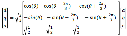 Park transformation requires the Phase Locked Loop to generate the reference signal with the same frequency and the phase angle of the actual signal.
DVR is connected in series between the source and the load as shown in Figure 9.

Figure 9: The electrical power circuit with the DVR.
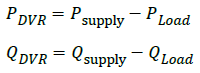
The power injected by the DVR during the compensation is as follows:
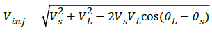
 From Figure 10, compensation voltage (Vinj) of the DVR can be calculated as following below:

Figure 10: The phaser diagram for the power circuit.
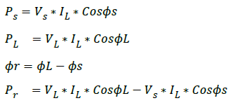
From the triangle abc in Figure 9
In recent years there has been a very significant increase in the number of applications of Fuzzy logic controller. Currently, there are numerous products on the market which use fuzzy logic control (mostly designed in Japan). Yasunobu and Miyamoto at Hitachi have designed a fuzzy controller for the Automatic Train Control (ATO) system which has been in use in the city of Sendai, Japan since July 1987. The two main operations of the system are Constant Speed Control (CSC) and Train Automatic Stop Control (TASC) [14]. Another application using Fuzzy logic controller is the Radio control of oral instructions on an unmanned helicopter used to sea rescue [15]. These applications have already produced results which illustrate the strength of the fuzzy logic control Figure 11.

Figure 11: The basic configuration of the fuzzy logic controller.
Fuzzification Interface
It converts a crisp input signal, error and change of error into fuzzified signal that can be quantified by level of memberships in the fuzzy set.
Knowledge Base
It consists of data base with linguistic definitions and rule base. Data base composed of input and output membership functions and provides the necessary information for fuzzification and defuzzification operations.
Rule Base
It consists of a set of linguistic rules which change the fuzzified input to the desired output as shown in the Figure 12.

Figure 12: The input membership function for the error.
Inference Mechanism
It infers the fuzzy control action from the knowledge base and rule base to convert the input conditions to fuzzified output.
Defuzzification Interface
It converts the fuzzified output to crisp control signal using the output membership's function, which acts in the system as the change in the control input. In this thesis centroid method is used for defuzzification.
The Input And Output Membership Function For Fuzzy Logic Controllers
The input and output membership function for the first, second and third controller is as shown in figures below (Figures 12-22).

Figure 13: The input membership function for the change of error.

Figure 14: The output membership function.

Figure 15: The input membership function for the error.

Figure 16: The input membership functions for the change of error.

Figure 17: The output membership function.

Figure 18: The input membership function for the error.

Figure 19: The input membership function for the change of error.

Figure 20: The output membership function.

Figure 21: (a) The rules set for the first controller (b) The rules set for the Second controller (c) The rules set for the third controller.

Figure 22: The set of linguistic rules.
Artificial Neural Networks (ANN)
Artificial Neural Network is an information processing system whose characteristics are similar to biological neural systems. It was designed based on the human brain. ANN has been widely used because of its accuracy and its ability to develop complex nonlinear models.
Artificial Neuron
Neurons in human brain act as a tool that 6 can perform processing of information of human senses. McCulloch and Pitt (1943) proposed a model neuron that has the characteristics of the transmission and receipt of information process that is similar to the process that occurs in biological neurons. This neuron was becoming a reference in the development of ANN. A neuron plays a role in determining the function and operation of the network. The mathematical models of neurons shown in the Figure 23 Can be represented by the following equation [16].

Figure 23: Artificial neuron.

The output of the neuron is dependent on the activation function
Activiation Function
There are several types of a non-linear, Differentiable activation functions, a non-linear activation functions can be used in networks trained with back propagation method. Hyperbolic tangent function [17].
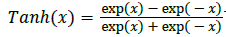 The output range of the tanh function is between -1 and 1. Logistic function [17].
 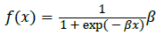 is the slope constant, and it always consider to be one but it can be changed. The output range of the logistic function is between 0 and 1.
Single Layer Neural Network
The simplest form of the Neural Network is in which only one layer of input nodes that send weighted input to subsequent layer of receiving nodes. Neurons are grouped into layers and layers are grouped into networks to form highly interconnected processing structures. One of the early examples of a single-layer neural network was called a perceptron.
Rosenblatt's Perceptron
Rosenblatt's Perceptron Is a neural network composed of a single layer feed-forward network using threshold activation function as shown in Figure 24.

Figure 24: The perceptron.
Threshold function is a non-differentiable, non-linear and its output either 0 or 1.
Multilayer Neural Network (MLN)
Neural Network which contains one or more hidden layers is called Multilayer Neural Network or Multilayer.
Perceptrons (MLP) as shown in Figures 24 and 25. Each hidden layer uses the same activation function.

Figure 25: Multilayer neural network.
Adaptive Neuro Fuzzy Inference System (ANFIS)
ANFIS is a combined between the fuzzy qualitative approach and the adaptive learning abilities of the neural network, where this system can be trained without a significant amount of expert knowledge that usually required for the standard FL Jang introduced Adaptive Neuro Fuzzy Inference System and mentioned that the (ANFIS) architecture can be utilized to model non-linear functions in control systems and predict a chaotic time series. ANFIS uses the Sugeno-type fuzzy inference system. ANFIS requires for training a set of input and output data, it can choose the parameters of the fuzzy inference system adaptively from the training data. It produces a set of membership functions to map the input data to output. The implementation of the ANFIS uses for tuning input and output the back propagation method and it uses for learning the hybrid algorithm. In this thesis the advantages of the ANFIS will be defined in modeling and control of a nonlinear system [18].
ANFIS Architecture is an adaptive network that uses supervised learning algorithm the function of ANFIS is similar to the Takagi-Sugeno fuzzy inference system.
It is clear from Figure 26, ANFIS architecture has five layers [19-21]. These layers are as follows:

Figure 26: ANFIS structure.
• Layer 1: It contains adaptive nodes to a function parameter. The output from each node is a degree of membership value that is given by the input of the membership function
• Layer 2: All nodes in this layer are fixed or non-adaptive. The output from each node is the result of multiplying of signal coming into the node and delivered to the next node Each node in this layer represents the firing strength for each rule
• Layer 3: The nodes in this layer are fixed or non-adaptive. Each node is a calculation of the ratio between the individual rule firing strength and the sum of all rules' firing strength. This result is known as the normalized firing strength
• Layer 4: It is determined the output from each rule by multiplying between the normalized firing strength and the set of parameters for each node. These parameters are known as consequent parameters
• Layer 5: The node in this layer is a fixed or non-adaptive node. This node is computed the output from the summation of all incoming signals from the previous node
Types of ANFIS
There are two types of ANFIS optimized PI controller whose contain one input (error) and one output as shown in Figure 27 and ANFIS optimized Fuzzy logic controller whose contain two input (error and change of error) and one output as in Figure 27.

Figure 27: ANFIS optimize PI.
ANFIS optimize PI gave us better results than PI in both linear and nonlinear loads but did not give us better results than Fuzzy logic where Fuzzy logic was far more efficient than (ANFIS optimize PI). Therefore we choose ANFIS optimize fuzzy logic whose called (fuzzy neural) where we has obtained better results than fuzzy logic when we added the 2nd and 3rd harmonics to the sag and swell Figure 28.

Figure 28: ANFIS optimize fuzzy logic.
Flow Chart for ANFIS Algorithm
The flow chart for ANFIS algorithm is as shown in Figure 29.

Figure 29: Flow chart for ANFIS algorithm.
Train Data and ANFIS Editor for the Fuzzy Neural Controllers
The train data of ANFIS is shown in Figures 27-29 and the editors of ANFIS are shown in Figures 30-35.

Figure 30: Train data for the first ANFIS.

Figure 31: Train data for the second ANFIS.

Figure 32: Train data for the third ANFIS.

Figure 33: ANFIS editor of the first controller.

Figure 34: ANFIS editor of the second controller.

Figure 35: ANFIS editor of the third controller.
The performance and efficiency of the DVR based on Fuzzy logic and Fuzzy neural will be tested with linear loads and non-linear loads.
Linear Load
The simulation and modelling of the system with DVR are shown in Figure 36. The control unit for the DVR based on Fuzzy neural.

Figure 36: The Simulink model of the test system with linear load.
Controller uses the Sugeno-type fuzzy inference system is shown in Figure 37.

Figure 37: The control system of the DVR.
Linear Loads
It is clear from the figures below that the Fuzzy logic controller and Fuzzy neural controller are capable of track and restore the load voltage fastly to its nominal value and keep the (THD) within acceptable limits. But when we added 2nd and 3rd harmonics to the voltage as shown in Figures 37 and 38 only Fuzzy neural was capable to keep the harmonics within permissible limits while Fuzzy logic was able to restore waveform only but was unable to keep the (THD) within acceptable limits.

Figure 38: (a) Load voltage without DVR; (b) Load voltage with DVR based on FL controller; (c) Load voltage with DVR based on FN controller.
Single line to ground fault: In Figure 38(a-c) SLGF (unsymmetrical sag) is simulated. It is started from 0.8s and it is kept until 0.95s. The load voltage is kept at the nominal value with the help of the DVR based on Fuzzy logic and Fuzzy neural.
Double line to ground fault: As shown in Figure 34 DLGF (unsymmetrical sag) is simulated. It is started from 0.8s and it is kept until 0.95s. DVR based on Fuzzy logic and Fuzzy neural is restored the load voltage to the nominal value Figure 39(a-c).

Figure 39: (a) Load voltage without DVR; (b) Load voltage with DVR on FL controller; (c) Load voltage with DVR based on FN controller.
Three phase fault: In Figure 40(a-c) three phases to ground fault (symmetrical sag) is simulated. It is started from 0.8s and it is kept until 0.95s. The load voltage is kept at the nominal value with the help of the DVR based on Fuzzy logic and Fuzzy neural.

Figure 40: (a) Load voltage without DVR; (b) Load voltage with DVR based on FL controller; (c) Load voltage with DVR based on FN controller.
Sag: In Figure 41, Symmetrical sag is simulated. It is started from 0.8s and it is kept until 0.95s. Figure 41(a-c) shows load voltage with compensation. As a result of the DVR based on Fuzzy logic and Fuzzy neural, the load voltage is kept at pre-sag voltage.

Figure 41: (a) Load voltage without DVR; (b) Load voltage with DVR based on FL controller; (c) Load voltage with DVR based on FL controller.
Swell: As shown in Figure 42(a-c) the three phases will be swelled to 150% for 0.15s from 0.8s to 0.95s. As can be seen the load voltage is kept at the nominal value with the help of the DVR based on Fuzzy logic controller and Fuzzy neural controller.

Figure 42: (a) Load voltage without DVR; (b) Load voltage with DVR based on FL controller; (c) Load voltage with DVR based on FN controller.
Sag with 2nd order harmonic and 3rd order harmonic: As shown in Figure 43(a-c) three phase sag with presence 2nd and 3rd harmonics is simulated. It is initiated from 0.8s to 0.95s. As can be seen, the load voltage kept at pre-sag voltage and without harmonic distortion with the help of the DVR based on Fuzzy neural. DVR based on Fuzzy logic was incapable to restore the load voltage to the pre-sag value and kept the THD within acceptable limits.

Figure 43: (a) Load voltage without DVR; (b) Load voltage with DVR based on FL controller; (c) Load voltage with DVR based on FN controller.
Swell with 2nd order harmonic and 3rd order harmonic: As shown in Figure 43(a-c) three phase swell with presence 2nd and 3rd harmonics is simulated. It is initiated from 0.8s to 0.95s. From the results, the load voltage kept at nominal value and within permissible total harmonic distortion with DVR based on Fuzzy neural. While DVR based on Fuzzy logic was incapable to restore the load voltage to the pre-swell value and kept the THD within acceptable limits Figure 44(a-c).

Figure 44: (a) Load voltage without DVR; (b) Load voltage with DVR based on FL controller; (c) Load voltage with DVR based on FN controller.
Non Linear Load
The simulink model with non-linear load is also investigated. The system and DVR are shown in Figure 45. The nonlinear load is 3-ph rectifier which supplies D.C. machine. It is clear from Figure 45 that Fuzzy logic controller and Fuzzy neural controller are able to restore the load voltage vastly to its nominal value and keep the (THD) within acceptable limits.

Figure 45: The Simulink model of the test system with non-linear load.
Table 2 shows the total harmonic distortion analysis, it is clear from this table that Fuzzy logic controller was unable to reduce the (THD) and make it within permissible limits in the case of 2nd and 3rd harmonics.
| Linear Load | Power Quality Problem | Without DVR | With DVR based on Fuzzy logic controller | With DVR based on Fuzzy neural controller |
| Single line fault (unsymmetrical sag) | 1.743 | 1.31 | 1.31 | |
| Double line fault | 4.846 | 1.406 | 1.406 | |
| Three Phase Fault (symmetrical sag) | 9.733 | 1.776 | 1.776 | |
| Sag (50%) | 2.554 | 1.39 | 2.55 | |
| Swell (50%) | 1.06 | 1 | 1.946 | |
| Sag with 2nd and 3rd Harmonics | 15.24 | 5.84 | 2.256 | |
| Swell with 2nd and 3rd Harmonics | 7.88 | 5.53 | 2.02 | |
| Non-Linear Load | Sag (50%) | 2.553 | 2.113 | 2.016 |
| Swell (50%) | 1.256 | 1.823 | 1.443 |
Table 2. Total Harmonic distortion for load voltage without DVR and with DVR based on fuzzy logic controller and fuzzy neutral controller.
There is a tremendous advantage to use of neural methodologies to train fuzzy system. Embedding fuzzy notions into neural networks is an area of active research, and there are few well known or proven results. By using the ANFIS algorithm we can embed empirical information and expert into a fuzzy system. This greatly expands and enhances the range of applications of fuzzy systems. In this research paper, the modeling and simulation of DVR has been achieved by Fuzzy logic controller and Fuzzy neural controller. From the results obtained, the fuzzy neural based DVR effectively mitigates 2nd order harmonic and 3rd order harmonic associated with the voltage sags and swells and reduced the load harmonics from greater than 10% to less than 2%. The proposed DVR also injects the appropriate voltage component to handles different fault conditions without any difficulties to keep load voltage constant and balanced under all power quality problems. From this work we can conclude that the applications whose one of its function is reduction the harmonics fuzzy neural be the appropriate option for such applications