Research & Reviews: Journal of Material Sciences
ISSN:2321-6212
ISSN:2321-6212
R V College of Engineering, India Dayananda Sagar University, India
Received Date: 06/10/2018; Accepted Date: 11/10/2018; Published Date: 18/10/2018
DOI: 10.4172/2321-6212.1000233
Visit for more related articles at Research & Reviews: Journal of Material Sciences
Two novel Cr-free nickel based welding wires were fabricated and used to weld austenitic grade stainless steel 304 (SS304) by Tungsten Inert Gas (TIG) welding process. Two welding wires designated as 3S (without Mn) and 4N (with 2% Mn) of % wt composition 43.499Ni, 25Fe, 10Mo, 10Cu, 10Co, 0-2 Mn, 1Ti, 0.5Al and 0.001C were fabricated and welded to SS304. Comparative studies of the joints welded by these two wires are presented. The weld joints were characterized for microstructure, mechanical and fracture properties. The microstructure of the weld interface showed presence of TiC and MoC precipitates in grains and along the grain boundaries which may be responsible for strength of the weld joints. The Unmixed zone in the joint welded by 3S wire is wider than that welded with 4N. Presence of 2% Mn in 4N wire promotes the formation of γ' (gamma prime) precipitates and hence may be responsible for better joint strength than joints welded by 3S wire. Tensile tests results showed joint strength due to 4N wire to be slightly superior (by 3.5%) to joint welded by 3S wire. However the ductility of the joint welded by 4N wire was lower by 6% compared to the joint welded by 3S wire. The hardness across the weld joints showed softer Heat Affected Zone (HAZ) and hence prone to failure during mechanical loading. The joint welded with 4N wire underwent significant amount of plastic deformation before failure. The joints welded with both the wires showed ductile mode of failure.
Nickel based Cr-free wire, Gtaw welding, Stainless steel, Microstructure, Characterization, Mechanical properties.
Presently, nickel based wires are widely used in industries for welding dissimilar materials such as inconel 82/182, ferritic low alloy steel and austenitic steel [1], alloy 800 and HP heat resistant steel [2], super alloys like Inconel 82/182 with and stainless steel to accommodate the difference in composition and thermal expansion of metals [3], precipitation of principal precipitates like Chromium carbides [4], weak resistance to weld solidification, resistant to micro fissures formation, to avoid carbon diffusion from carbon steels to stainless steel, and to avoid oxidation [5-9].
Cr alloying element is added into nickel alloys to improve their weld ability [10], mechanical strength [11,12], corrosion resistance and resistance to cracking of weld joints [13,14]. Although addition of Cr drastically improves mechanical and corrosion properties but its weld fumes contain carcinogenic hexavalent chromium (Cr+6), which is harmful to welders health [15]. Severity of the weld fumes increases, when welding is done in closed chambers such as within the power plant boilers [16], interiors of ship where task of providing exhaust system is not only expensive but also difficult [17]. OSHA has recommended welding of stainless steel by Cr-free electrodes/wires [18].
In this direction, YeongHo Kim et al. developed Cr-free weld electrodes by reduction/total elimination of Cr concentration in weld alloy by replacing Cr alloying elements with other elements such as Molybdenum (Mo), Copper (Cu) [19], whereas Jeffrey William Sowardset et al. continued the work of his predecessor by developing welding wire materials by adding elements such as Titanium (Ti), Cobalt (Co), Manganese (Mn) etc [20-23]. Addition of up to 10% by weight of Mo into nickel alloy not only increased its mechanical strength but also improved resistance to pitting corrosion [24]. Further, the combination of Cu and Mo as well as Ti and Mo alloying elements improved the mechanical strength as well as corrosion resistance in Ni based alloy [25,26]. Ti helps formation of carbides in the nickel alloy and hence improved mechanical strength along with reduction in porosity in weld joints, Ti also contributes to the formation of equiaxed dendrites, thus increasing ductility of the weld joint [27-30].
Cui et al. recommended addition of Co to the weld material as it has good solubility with most of the alloying elements and forms solid solution strengthening to weld material as well to the weld joint and Shoemaker et al. advised addition of Mn to the electrode materials for Cr substitution as it promotes strengthening of the weld joint after weld pool solidification [31,32]. Co improves the resistance to cracking due to micro fissures in the austenitic stainless steel and Mn mitigates the harmful effects of Sulphur by forming MnS instead of FeS [33]. Although many researchers have worked on partially replacement of Cr alloy with other elements to maintain their mechanical and corrosion properties, only few have focused on development of Cr free Ni base alloy using Cu, Mo and Co as alloying elements [20-23]. As per author’s knowledge, no research work on replacing Cr by multiple elements such as Ti, Al, Mn and Co in Ni based filler metal is attempted. The following objectives were formulated:
1. Development and Characterization of two Cr free Ni based filler metal with and without Mn respectively
2. Investigation of weld ability of the joints welded by two wires such as heat affected zone, unmixed zone, partially melted zones and weld fractures.
3. Characterization of weld joints by strength, micro-hardness and impacts studies.
The base material was SS304 plates in solution annealed condition having dimensions of 160 mm × 70 mm × 6 mm. Chemical compositions of SS304 is given in Table 1. Nickel-based filler metal constituting 40-50% Ni exhibit outstanding strength and corrosion resistance at room and elevated temperatures [34] due to their austenitic structure. Two Cr free filler metals designated as 3S and 4N are prepared using open top induction furnace and their final compositions are shown in Table 2. These filler metals were machined to length 200 mm × diameter of 3.2 mm using wire cut EDM process.
Table 1. Chemical compositions of SS 304 alloy.
| Element type | Cr | Mn | Ni | Si | C | P | S | Fe | Total |
|---|---|---|---|---|---|---|---|---|---|
| % weight | 18-20 | 2 | 8-10.5 | 1.0 max | 0.08 | 0.045 | 0.03 | Bal | 100 |
Table 2. Chemical compositions of two electrode rods.
| Composition (%) | Ni | Fe | Mo | Cu | Co | Mn | Ti | Al | C | Total |
|---|---|---|---|---|---|---|---|---|---|---|
| 3S-Alloy | 43.499 | 25 | 10 | 10 | 10 | Nil | 1 | 0.5 | 0.001 | 100 |
| 4N-Alloy | 43.499 | 23 | 10 | 10 | 10 | 2 | 1 | 0.5 | 0.001 | 100 |
The Base metal specimens were machined to obtain single V groove, butt joint configuration with 3.2 mm root gap opening, 80° included angle and root face of 1 mm [30]. The weld joint as shown in Figure 1, was welded by two-pass TIG welding process and the welding parameters are shown in Table 3. The weld joints were obtained using automatic TIG welding machine of make “Master TIG” of CK worldwide. After welding, joints were cleaned of scales/oxide layers by wire brush and exposed to X-rays (make Philips MG225) to detect defects such as solidification cracks and shrinkage porosity in welds. For microstructural studies, transverse section specimens were ground on SiC emery paper step by step from 80 to 2000 grit and then were polished on a nylon cloth with 0.1 μm diamond paste for mirror finish. Specimens were chemically etched using marbles reagent (4 gm CuSO4 + 20 mL distilled H2O+ 20 mL con.HCL). The filler metal, base metal and weld interface were examined by optical microscope (OM) and scanning electron microscopy (SEM) to investigate microstructural changes. Chemical compositions of both weld interface and filler metal were determined by energy dispersive X-ray spectrometer (EDS)(EDX-Shimadzu and XRD-7000 Maxima X). Dilution levels were determined metallographically, by measuring individual geometric cross-sectional areas of the deposited filler metal and melted base metal. Dilution of the weld joint is the ratio of the melted base metal (Abm) to the total melted cross sectional area of the filler metal and base metal (Abm+ Afm) combined [35].
Table 3. TIG welding Parameters for both joint.
| Welding Parameters | Values |
|---|---|
| Welding speed (mm/sec) | 3 mm/s |
| Ar gas Flow rate (litres/min) | 8 Litres/min |
| Current (amps) | 115 Amps |
| Arc voltage (volts) | 20-22 volts |
| Filler Type | 3S and 4N |
| Stand-off distance | 2 mm |
| Filler size | ø3.2 x 150 mm |
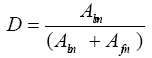 (1)
(1)
For tensile test, specimens were taken in transverse direction as shown in (specimen superimposed on the weld plates) (Figure 1). Tensile tests on the specimens of dimensions (gauge length of 60 mm, width of 10 mm and thickness of 6 mm) and strain rate of 1 mm/min were performed [30]. The microhardness across the weld interface was measured using a Vickers microhardness tester as per ASTME-384 with a load of 500 g. Toughness of the weld joint was measured using computerised Charpy tester on the V-notched specimens of dimensions 55 mm × 10 mm × 6 mm [3]. To find failure mechanism, fracture surface of tensile test specimen were studied using SEM. The average dilution levels as calculated by Equation 1 for weld joints 3S/SS304 and 4N/ SS304 are 32 ±5 % and 31±4 % respectively.JMAT PRO (Sente Software Ltd., Surrey, U.K.) material property simulation software was used to predict the effect of Mn alloying element on the phase stability of the alloys 3S and 4N.

Figure 1. Schematic diagram of tension test specimen superimposed on base plate.
In the following sections results and discussion of Microstructures and Mechanical properties of Base, Filler Materials presented.
Base and Filler Metal Microstructure
Figure 2 shows the microstructure of the base metal SS304. It consists of equiaxed austenitic grains (EAG), annealed twins (AT), minor ferritic (MF) grains and dark finely dispersed carbide precipitates (CP) in grain boundaries and in austenite matrix. Full austenitic structure of SS304 implies better toughness and corrosion properties at elevated temperatures [35]. The composition of dark carbide precipitates may be Cr23C6 or Cr6C [36]. Figure 2b and 2c show the microstructure of the as-cast filler metal 3S alloy at different magnifications. Figure 2d and 2e shows the microstructure of as- cast filler metal 4N alloy at different magnifications. Both consists of fine dendrites in gamma solid solution. 3S and 4N filler metal contain about 25% and 33% by wt of γ' (gamma prime) respectively. Both microstructures predominantly consist of fine, Mo rich and minor contents of Ti rich M6C type (M represents Metal type) carbide precipitates (by EDS) at the interdendritic regions and along the grain boundaries. Primary strengthening phase γ' is well dispersed in the matrix of the nickel filler metal and its composition may be Ni3Ti/Al. The carbide and γ' precipitates vary in its size and location. The XRD results as shown in Figure 3a and 3b for both 3S and 4N alloy confirm the presense of γ (gamma solid solution), and precipitates like γ' (gamma prime), Mo rich and minor contents of Ti rich M6C.

Figure 2. Shows the optical micrographs of base metal SS304. (2b-2c) shows microstructure of 3S Alloy with different magnification and (2d-2e) shows the microstructure of 4N alloy for different magnification.

Figure 3. Shows the X ray diffraction patterns of as-cast and 4N alloy.
Weld Interfacial Microstructure
The weld interface between joints 3S/SS304 and 4N/SS304 compared to base materials differs in morphology, composition and properties. Figure 4a and 4b shows the optical micro graphs of the weld interface. Figures 5a-5d and 6a-6d shows SEM microstructures and EDS plots of weld joint for 3S/SS304 and 4N/SS304 respectively. The interface of the weld joints of both 3S/SS304 and 4N/SS304 is continuous and did not reveal micro cracks or porosity, this may be due to the addition of higher alloy element Ti (1%) and Al (0.5%). Ti and Al not only reduces the porosity in the weld but also influences the pinning effect on the migration grain boundary (MGB) as shown in Figure 7a along with Titanium Carbide (TiC) (shown by bright spots in Figures 5d and 6d [36]. The weld interface can be distinctly divided into four regions, the base metal (BM), heat affected zone (HAZ), unmixed zone (UZ) and weld metal zone (WM). The width of UZ for 3S/SS304 (75 μm) is higher than that of 4N/SS304 (50 μm) due to difference in melting temperatures of filler metal 3S(1380°C) and 4N (1340 °C). The melting tempeature of 3S is very close to SS304 base metal (1440°C) and hence results in wider UZ [37]. The equi-axed dendritic structure could be observed in the unmixed zone in Figures 5c and 6c. Shorter primary arm dendrite spacing (PADS) is mainly due to presence of 1% Ti [30]. The welding interface of Figures 5d and 6d shows the distribution of dark Molybdenum carbide (MoC) and bright TiC precipitates along the grain boundaries. Figures 5a and 6a correspond to chemical composition of the dendritic structure where as in Figures 5b and 6b shows chemical composition of TiC precipitate. Figure 6e corresponds to the chemical composition (EDS plots) of the MoC precipitates formed within and sometimes along the grain boundaries. The HAZ for the joint 4N/SS304 (50 μ) is shorter than 3S/SS304 (75 μ). This may be attributed to the presence of 2% Mn in 4N alloy which reduces the thermal conductivity of the weld pool and hence limits the heat transfer to HAZ resulting in shorter width [38]. Similar observation was made by Sireesha, et al. [2]. Darker grain boundaries in HAZ can be observed in both types of weld joints due to TiC precipitates formed at grain boundaries during the weld pool solidification, evidence of which is shown by EDS in Figures 5b and 6b. On the other hand, the grain growth at HAZ is due to increase in number of weld passes, heating and reheating of the HAZ of the base metal resulting in grain growth which is shown in Figures 5c and 6c. In the partially mixed zone (PMZ) of the weld joints, elements of filler metal fuse with the base metal elements resulting in dilution of the electrode materials as shown in Figure 7b. The area of PMZ appears to be narrow but this zone forms delta structure with other zones as shown in Figure 7b.

Figure 4. Weld interface of the joint (a) 3S filler metal and SS 304 base metal (b) 4N filler metal and SS 304 base metal.

Figure 5. Shows the SEM and EDS results of the weld joint 3S/SS304, (a) EDS results showing Mo, Ni, Fe, Cu rich phase, (b) EDS results of presence of TiC Precipitate, (c) SEM image of the weld joint 3S/SS304, (d) Magnified view of presence of MoC and TiC precipitate, (e) EDS results of MoC precipitate.

Figure 6. Shows the SEM and EDS results of the weld joint 4N/SS304.(a) EDS results showing Mo, Ni, Fe, Cu, Mn rich phase, (b) EDS results of presence of TiC precipitate, (c) SEM image of the weld joint 4N/SS304, (d) Magnified view of presence of TiC precipitate.

Figure 7. The presence of (a) Solidification Grain boundary and migration grain boundary and (b) Magnified view of microstructure of unmixed zone, microstructure of weld zone.
The tendency of delta dendritic boundaries to melt in alloy weld zone (WZ) is attributed to the enrichment of Mo in these boundaries. Mo in weld zone not only lowers the melting point constitutionally but also forms low melting carbide-austenite eutectics, during solidification. Distinct boundaries ofsolidification grain boundary (SGB) and migration grain boundary (MGB) are formed in weld interface zone (WM) as shown in Figure 7a. Such grain boundaries are formed due to the collision of packets of grain and sub grains at the time of solidification. Mo and Ti Carbides are formed along SGB and MGB due to lowering of partition coefficient of Mo in the presence of Iron [39] (Figure 4).
The stress-strain behaviour of 3S/SS304 and 4N/SS304 weld joints is shown in Figure 8. The ductility of the weld joints are 24% and 18% respectively. Again the stress-strain behaviour for the base metal SS304 (BM), filler metal (FM) 3S and weld joint (WJ) 3S/SS304 are shown in Figure 8a and BM, second filler metal 4N and WJ 4N/SS304 are shown in Figure 9b. In Figure 9a and 9b, the BM, both types of FM and WJ have same behaviour upto elastic limits (1% elongation) and afterwards all three curves clearly deviate among themselves. The Ultimate Tensile Strength (UTS) of both FM alloys are almost the same but ductility of 4N is slightly less than 3S alloy (4N-18% and 3S-20%) (Table 4).Also, FM alloy has little higher strength than the base alloy. Similar material properties are the requirements for good weldability properties [40,41]. Strength of both type of WJ (3S/SS304 and 4N/ SS304) are less than Filler Metals (3S and 4N) and BM (SS304). This can be attributed to the degradation of mechanical properties due to high cooling rate of the HAZ after TIG welding process. Though cracks are initiated at HAZ, no failure was seen in weld joints (WZ) during tensile tests which implies stronger weld joint. Although both FMs show almost same trend of strength and ductility, the WJ 4N/SS304 and 3S/SS304 show different behaviour. The joint 4N/SS304 has higher strength (591 MPa) but joint 3S/SS304 has higher ductility (24.66%) as shown in Table 3. Increase in the strength of the joint 4N/SS304 compared to 3S/ SS304 may be attributed to the presence of 2 % Mn in the filler metal 4N [40]. Figure 10 shows the effect of the addition of Mn on the phase stability of weld interface 4N/SS304 joint as computed by JMATPRO. Addition of Mn increases the wt % of γ' and NiAl precipitates which strengthens phase in nickel alloy, which in turn increases the weld strength. Addition of Mn not only increases γ' and NiAl precipitates by 2% but also decreases the formation of other Tetragonal closed packed (TCP) phases. Increased wt% of γ' and Nickel Aluminide (NiAl) precipitates in the weld interface 4N/SS304 act as obstacles for the dislocation motion during the tensile tests.

Figure 8. Stress Strain behaviour of weld joints with strain rate of 1mm/min.

Figure 9. Stress-strain behaviour of base alloy, filler alloy and weld joint at strain rate of 1 mm/min.

Figure 10. Effect of Mn on the phase stability of 4N alloy simulated by JMAT Pro.
Table 4. Mechanical properties for weld joints 3S/304 and 4N/304.
| Material Type | Designation | UTS (MPa) | % El | Impact Energy (J) |
|---|---|---|---|---|
| Base Plate | SS 304 | 628 | 35 | 101.1 |
| Filler material | 3S | 632 | 20 | 96.2 |
| Filler material | 4N | 635 | 18 | 98.3 |
| Weld Joint | 3S/SS304 | 571 | 24.66 | 100.7 |
| Weld Joint | 4N/SS304 | 591 | 18.02 | 91.3 |
However the ductility of 4N/SS304 is less than that of 3S/SS304 weld joint by 6% which may be due to influence of Mn. Presence of Mn has dual role in steel, first it solution-hardens [41] the steel thereby increasing the strength and toughness and secondly it refines the pearlitic structure thereby decreasing the ductility of the steel. Figure 11 shows the hardness profile across the weld interface which indicates the effect of welding temperature on the weld joint and base metals. The weld joint shows maximum hardness of 230 HV and 223 HV for 4N/SS304 and 3S/SS304 weld joint respectively which are much more than that of base SS304 alloy (175 HV) but at HAZ region the hardness is lower than that of both base alloy and weld joints (163 HV) hence the failure could be seen near weld joints due to grain modification (larger grain size shown in Figure 5c and 6c due to effect of heat by two pass welding. The gradual decrease of hardness in HAZ of the weld joint is reported in other dissimilar welds also [42]. The toughness (impact strength) of FM, BM and WJ are given in fifth Column of Table 3. The base metal has highest impact strength, followed by filler metals and weld joints. Weld joint 3S/SS304 shows almost the same impact strength as that of base metal due to its ductility. On the other hand, WJ 4N/SS304 has lesser impact strength (Figure 12).

Figure 11. Hardness profile across the weld interface for the joint 4N/SS304 and 3S/SS304.

Figure 12. Shows the fractography of (a) 3S alloy, (b) 4N alloy and (c) SS304 base material with micro voids (MV), dimples(D).
deformation before failure compared to the weld joint 3S/SS304 weld joint (Figure 13b). The wide dimples are the confirmation of the presence of precipitates (NiAl/Ti, Mo6C and TiC) which was formed due to addition of Mn alloying element. 2% Mn in 4N alloy promotes the formation of more precipitates than compared to 3S alloy [40] (Figure 10). Reminiscence of secondary particles (like precipitates) in the microvoids can also be seen.The size of the microvoids varies from 30-60 microns (Figure 14).

Figure 13. Shows the fractography of (a) 3S/SS304 weld joint (b) Magnified view of 3S/SS304 weld joint with micro voids (MV), dimples (D), crack(C).

Figure 14. Shows the fractography of (a) 4N/SS304 weld joint (b) Magnified view of 4N/SS304 weld joint with micro voids (MV), dimples (D).
The findings of the research work are summarized below
1. The microstructure of the weld interface consists of distinct region such as BM, HAZ, UZ. Due to multi pass welding, grain growth in the HAZ was observed. Hence rendering the HAZ region susceptible for failures.
2. Presence of TiC, MoC precipitates strengthen the grain and grain boundaries in the weld joints.
3. UZ in the joint 3S/SS304 is wider than that of 4N/SS304 due to nearness of the melting point
4. 25-35% dilution of filler metal in the base metal resulted in the formation of PMZ in the weld interface.
5. Presence of 2% Mn in 4N filler metal promotes the formation of gamma prime precipitates and hence joint strength in 4N/ SS304 is slightly higher compared to 3S/SS304.
6. The ductility of the weld joint 4N/SS304 was lower compared to joint 3S/SS304.
7. Fractured surface of the joints revealed ductile mode of fracture for both the types of Weld Joints.