Keywords
|
| BCD Converter, FPGA, Image Processing,VHSIC hardware description language. |
INTRODUCTION
|
| In this project, the system is designed by using spartam3E, because Need for low power VLSI chips arise from such evolution forces of integrated circuits. While the power dissipation increases linearly as the years go by, the power density increases exponentially, because of the ever-shrink size of the integrated circuits. It requires less power and the system is cheap. It requires less space and easy to install.So many problems for assembly side are can be solved by introducing this project. It will provide correct information about the product. This project is going to implement in spartan3E, it operate on less power and less space, and also it is user friendly and cost effective.This project can be used in manufacture company,factories to maintain the quality product. This project helps us find the correct product within fraction of seconds. |
II. RELATED WORK
|
| In [1] author used based on the observed measurement, pre-processing module based on morphology filter which occupies most execution time will replaced by Sobel Filter. Then Sobel Filter will be implement on hardware(FPGAs) part of the platform.In [2] author used Two independent ways to classify applications are proposed,according to the inspected features of the industrial product or process and the other according to the inspection independent characteristics of the inspected product or process.In [3] author used for this following are executed. 1)Image is taking by camera and stored in PC.2)Both current and circumstances images are sent to FPGA by serial communication 3).Background subtraction is done to obtained moving object.4)Position of moving objects located on FPGA.In [4] author Used Different methods are used for fault analysis such as short time Fourier transforms (STFT), Wavelet analysis (WA), Model based analysis, cepstrum analysis etc. This paper presents a study of rolling bearing faultdiagnosis of induction motor based on reconfigurable logic.In [5] author used Two different hardware architectures of two dimensional (2-D) video surveillance have been implemented as a coprocessor in an embedded system. It is direct implementated video surveillance by Motion human detection algorithm.In [6] author used this work proposes an embedded novel architecture on FPGA which is able to extract the background on resource-limited environments and offers low degradation (produced because of the hardware-friendly model modification). |
III. OVERVIEW OF VLSI DESIGN
|
| There is various interpretation of the Moor’s law that predicts the growth rate of integrated circuits. One estimate places the rate at 2X for every eighteen months. Others claim that the device density increases ten-fold every seven years. Regardless of the exact numbers, everyone agrees that the growth is rapid with no signs of slowing down. New generations of processing technology are being developed while present generation devices are at a very safe distance from the fundamental physical limits. Need for low power VLSI chips arise from such evolution forces of integrated circuits. While the power dissipation increases linearly as the years go by, the power density increases exponentially, because of the ever-shrink size of the integrated circuits. If this exponential rising in the power density were to increase continuously, a microprocessor designed a few years back, would have same power as that of the nuclear reactor. Such high power density introducing the reliability concerns such as the electro migration, thermal stresses and hot carrier induced device degradation, result in the loss of performance. |
| Another factor that fuels the need for low power chips is the increased market demand for portable consumer electronics powered by batteries. The carving for smaller, lighter and more durable electronic products indirectly translates to low power requirement.Battery life is becoming a product differentiator in many portable systems. Being the heaviest and biggest component in many portable systems, batteries does not have experienced the similar rapid density growth compared to the electronic circuits. The main source of power dissipation in these high performance battery-portable digital systems running on batteries such as note-book computers, cellular phones and personal digital assistance are gaining prominence. For these systems, low power consumption is a prime concern, because it can directly affects the performance by having effects on battery longevity. In this situation, low power VLSI design has assumed great importance as an active and rapidly developing field.At the circuit design level, considerable potential for power savings exists by means of proper choice of logic style for implementing the combinational circuits. Because all the important parameters governing power dissipation switching capacitance, transition activities, and short circuits currents strongly influenced by the chosen logic style. |
IV.MULTI-POINT FUEL FLUID LEVEL SENSOR
|
| Level Sensor series, capable of detecting up to nine sensor points, uses a resistor network in conjunction with specialized magnetic Nitrile Butadience Rubber (NBR) floats to detect multiple fuel level points... |
| Full application: Fuel Multi level Point Sensor |
| Features: |
| • Ability to activates and control switching up to nine switching points. |
| • Hermetically sealed. |
| • Ability to work under very hot and cold temperature as normal operation. |
| • Ability to withstand toxic chemical atmosphere without any material degradation. |
| • Dynamic tested contacts. |
| • Reliable switching. |
| • Designed to handle high shock environment. |
| • Millions of reliable switching operation. |
V.PROPOSED SYSTEM
|
| This project aims at designing a system to visual inspection and quality control are performed by human expert.Although humans can do job better than machines in many case, they are slower than the machines and get tired quickly.Human experts are difficult to find or maintain in an industry, require to training and their skills may take time to develop. There are also case were inspection tends to be tedious or difficult, even for best-trained experts. In certain application, important information must be quickly or repetitively extracted and used.In some environments inspection may be difficult. Computer vision may effectively replace human inspection in such demanding cases. |
| First, a computer is employed for processing the object images. This is achieved by apply special purpose image processing analysis and classification software. Images are usually acquired by one or more cameras placed at the scene under examination. The positions of the cameras are usually fixed. In most cases, industrial automation systems are designed to inspect only known object at fixed positions. The scene is appropriately brighten and arranged in order to facilitate the reception of the image features necessary for processing and classification. These features are also known in advance. When the process is highly computationally intensive and exceeds the processing capabilities of the main processor, application specific hardware (ASICs, or FPGAs) is employed to alleviate the problem of processing speed. The results of this processing can be used to: |
| • Control a manufacturing process. |
| • Propagated to other external devices for further processing |
| • Characterizing defects of faulty items and take actions for reporting and correcting these faults and replacing or removing defective parts from the production line. |
| Image is captured by camera and store in PC.Both Original image and Testing image are sent to FPGA by a serial communication and then BCD converter is done to obtain image.Position of image is located on FPGA.If the identity matches it will display the “matching” about the image in the 16x2 LCD, else it will display “not matching”. Likewise the system maintains the product till a particular time, it analyzes the matched image and it will store it in the PROM. Among the stored IMAGE in SPARTAN-3 FPGA kit by interfacing a test circuit with the PC using the RS232 cable.So,the efficiency increased using this method. |
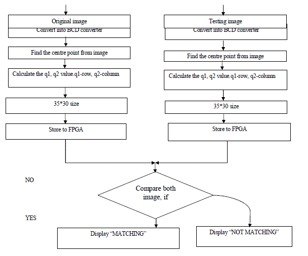
VI. FLOW CHART FOR PROPOSED WORK
|
| The Original image is captured by camera then the image is converted to BCD converter .Find the centre point from the image and then calculate the q1,q2 values, Where q1-row,q2-column.The size is 35*30 and store to FPGA.Next the testing image is also captured by camera.Same process is done and then store to FPGA.And compare the both image.If image is same,the LCD Display shows “MATCHING” and image is not same,the LCD Display shows “NOT MATCHING”.This process is described in flow chart: |
 |
VII. RESULT AND DISCUSSION
|
| In this case the image capturing is done by USB camera connected to the PC. Image is send to FPGA by MATLAB. In MATLAB trigger set and firstly when gets trigger the first image is stored as background and all other images are send to FPGA.For software development Matlab 2010 and Xilinx ISE are used. Moving object detected can be seen on Matlab as images and position of moving object can be seen as LEDs glows on the FPGA and display the result in LCD Display. |
| In the fig 2, it shows the original image, |
| In the fig 3,Here picture shape has been changed compared to fig 1.In the LCD Display shows the”NOT MATCHING”. |
| In the fig 4,Here the picture size has been changed.So the LCD Display shows “NOT MATCHING”. |
VIII.CONCLUSION
|
| In this work amaterial fault detection using FPGA wasdeveloped.Additionally, the system is capable to detect an objectby ExtrACTING ITS SHAPE AND CALCULATEthe centre. The OBJECTposition is send to a PC or another platform via RS-232 interface. |
Figures at a glance
|
 |
 |
 |
 |
 |
| Figure 1a |
Figure 1b |
Figure 2 |
Figure 3 |
Figure 4 |
|
| |
References
|
- Hong ThiKhanh Nguyen., Cecile Belleudy., and Pham Van Tuan., “Fall Detection Application on an ARM and FPGA Heterogeneous Computing Platform”,International Journal of Advanced Research in Electrical, Vol.3, pp.2320 – 3765, 2014.
- Elias, N. Malamas., Euripides, G.M. Petrakis., MichalisZervakis., “A Survey on Industrial vision systems,Applications and Tools”,pp.2-38.
- Megha Mahesh Chakorkar., M.M. Patil., “Moving Object Detection By Background Subtraction Algorithm in FPGA”.IRF International Conference,pp.12-15,2014.
- S.M. Shashidhara.,P. SangameswaraRaju., “FPGA Based Embedded System Development for Rolling Bearings Fault Detection of Induction Motor”,International Journal of Reconfigurable and Embedded Systems (IJRES), Vol.2, pp.127-134, 2013.
- K. SarathBabu., K. Surendranath Reddy., U.Yedukondalu., “FPGA Implementation of Motion Human Detection Based On Background Subtraction”,Int. Journal of Engineering Research and Applications,Vol.3, pp.2005-2009,2013.
- Enrique, J. Fernandez-Sanchez Javier Diaz and Eduardo Ros., “FPGA Implementation for Real-Time Background Subtraction Based on Horprasert Model Rafael Rodriguez-Gomez”, Vol.12, pp.585-611,2012.
|