Keywords
|
| Adaptive routing, network-on-chip, prediction model, path diversity. |
INTRODUCTION
|
1.1 GENERAL
|
| Recently the trend of embedded systems has been moving toward Multi Processor Systems-on-Chips (MPSoCs) in order to meet the requirements of real-time applications. The complexity of these SoCs is increasing and the communication medium is becoming a major issue of the MPSoC. Generally, integrating a network-on-chip (NoC) into the SoC provides an effective means to interconnect several Processor Elements (PEs) or Intellectual Properties (IP). The NoC medium features a high level of modularity, flexibility, and throughput. The NoC comprises routers and interconnections allowing communication between the PEs and/or IPs. The NoC relies on data packet exchange. The path for a data packet between a source and a destination through the routers is defined by the routing algorithm. Therefore, the path that a data packet is allowed to take in the network depends mainly on the adaptiveness permitted by the routing algorithm (partially or fully adaptive routing algorithm), which is applied locally in each router being crossed and to each data packet. |
| The area and speed on a single chip now faces the big challenge on a single chip, more and more processing elements now are placed on System on chip. Network-on- Chip (NoC) is on a chip becomes a primary factor which limits the performance and power consumption. As the switch speed of crossbar switch increases rapidly, on big problem we should a new method for on chip communication to solve the problem that challenges the system on chip. |
1.2 NETWORK-ON-CHIP
|
| Network on Chips are critical elements of modern System on Chip (SoC) as well as Chip Multiprocessor (CMP) designs. Network on Chips (NoCs) helps to manage high complexity of designing large chips by decoupling computation from communication. SoCs and CMPs have a multiplicity of communicating entities like programmable processing elements, hardware acceleration engines, memory blocks as well as off-chip interfaces. With power having become a serious design constraint, there is a great need for designing NoC which meets the target communication requirements, while minimizing power using all the tricks available at the architecture. |
| As the number of architectural blocks that are integrated on a single chip continues to rise, overall system performance and cost become increasingly dependent on the efficiency of the NoCimplementation. Although regular topologies are preferred for building NoCs, heterogeneous blocks, fabrication faults and reliability issues derived from the high integration scale may lead to irregular topologies. In this situation, efficient routing becomes a challenge. Although table-based routing allows the use of most routing algorithms on any topology, it does not scale in terms of latency and area. |
| The importance of low latency lies in the fact that the delay of packet sent from source to destination is greatly reduced, yielding a much more balanced traffic load. Therefore, achieving low latency is an ultimate goal for us in designing a router. The routers can be arranged in an arbitrary topology and are connected with an arbitrary number of modules. Furthermore, a flit (the basic transmit unit in NoCs) can be propagated using different routing, switching and arbitration schemes. On the one hand, this large variety of parameters is the essence for high flexibility. On the other hand, it spans a very large design space. |
| This makes the optimization of the interconnection infrastructure challenging. A high accuracy is essential to acquire reliable information for the design optimization already in an early design phase. The authors of this paper observed that existing analytic models are not able to provide a sufficient accuracy. This is especially the case for NoC routers using the popular round-robin arbitration scheme. This arbitration scheme offers a low complexity and local fairness and is therefore used in many existing network-on-chip designs for handling best-effort traffic. |
| The arbitration scheme has a strong impact on the whole network throughput, bottlenecks and path latencies. Therefore, it influences design decisions significantly. But Wrong design decisions can lead to over-provisioning, i.e., waste of chip area. On the other hand, performance requirements may not be fulfilled, which is even worse. Thus, it is essential to employ effective models that offer a high accuracy. Therefore, in this paper, we alter a latency model, which simultaneously considers the number of output path and buffer status, to predict the latency condition of the output channels. |
| Based on this model, we propose valuable packet switching method to overcome congestion problem in NoC. Also it can be further efficiently capitalize on the flexibility and is expected to achieve with a reduction of area. Based on this, many important network performance metrics, such as mean Latencies or network throughput can be derived. Like in any other network, router is the most important component for the design of communication back-bone of a NoC system. |
| In a packet switched network, the functionality of the router is to forward an incoming packet to the destination resource if it is directly connected to it, or to forward the packet to another router connected to it. It is very important thatdesign of a NoC router should be as simple as possible because implementation cost increases with an increase in the design complexity of a router. |
1.3 NOC ARCHITECTURE
|
| A variety of interconnection schemes are currently in use, including crossbar, buses and NOCs. Of these, later two are dominant in research community. However buses suffer from poor scalability because as the number of processing elements increases, performance degrades dramatically. Hence they are not considered where processing elements are more. To overcome this limitation attention has shifted to packet-based on-chip communication networks, known as Network-On-Chip. |
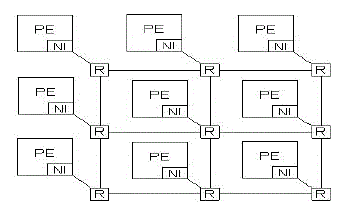
| Fig 1.1 shows the architecture of NoC. A typical NoC consists of computational Processing Elements (PEs), Network Interfaces (NIs), and routers. The latter two comprise the communication architecture. The NI is used to packetize data before using the router backbone to traverse the NoC. Each PE is attached to an NI which connects the PE to a local router. When a packet was sent from a source PE to a destination PE, the packet is forwarded hop by hop on the network via the decision made by each router. For each router, the packet is first received and stored at an input buffer. Then the control logics in the router are responsible to make routing decision and channel arbitration. Finally, the granted packet will traverse through a crossbar to the next router, and the process repeats until the packet arrives at its destination. |
II EXISTING SYSTEM
|
2.1 ROUTER ARCHITECTURE OF NOC
|
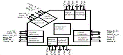
| Fig 2.1 shows the router architecture of NoC. It consists of five ports such as east, west, north, south and local port. It also has a central cross bar switch. Inside each port there are two channels namely input and output channels. Data can be routed from any of the input port to the any of the output port. Each input channel and output channel has its own decoding logic which increases the performance of the router. Buffers are used at all ports to store the data for a short time span. The store and forward method is used here for data transmission. Control logic is present to make decisions to grant access to a port request |
| In this way communication is established between input and output ports. The connection or configuration is made between both with the central cross point matrix. According to the destination path of data packet, control bit lines of cross point matrix are set. The movement of data from source to destination is called switching mechanism. The packet switching mechanism is used here, in which the flit size is 8 bits .Thus the packet size varies from 8 bits to 120 bits. |
2.2 XY ROUTING ALGORITHM
|
| As XY routing algorithm is more advantages during the situations like dead lock and live lock problems. We use this one for both the existing system and proposed system. |
| Fig 2.2 shows the XY routing algorithm. It routes the packet first in X direction (Horizontal) to the correct column and then in Y direction (Vertical) to the receiver. Then the routing operation is done on the basis of the conditions. X>Y, X=Y, X<Y. Table 2.2 shows the routing procedure. The coordinates (X1, Y1)is compared with the router address (X2, Y2). While the operation takes place in a horizontal direction. If X1=X2then the packet is forwarded in the horizontal direction towards east port or west port. If X1>X2 then the packet is forwarded towards west port. If X1<X2 then the packet routed to the west port. Now the operation takes place in a vertical direction. If Y1=Y2 then the packet routed in a vertical direction towards north or south port. If Y1>Y2 forwarded to the south port. If Y1<Y2 routed to the north port. In XY routing, a packet is routed along a row first, then routed along the appropriate column to the destination. This save area and reduced number of clock cycles required for requests. |
PROBLEMS ON ROUTING
|
| Problems on oblivious routing typically arise when the network starts to blocktraffic. The only solution to these problems is to wait for traffic amount to reduce and try again. Deadlock and livelockare potential problems on both oblivious and adaptive routing. |
2.3 ROUND ROBIN ARBITRATION
|
| The arbiter traps the source and destination address from the output of buffer and generate the control signal so that inputdata from source side sending to the output port.Arbiter controls the arbitration of the ports and resolvecontention problem. It keeps the updated status of all the portsand knows which ports are free and which ports arecommunicating with each other. Packets with the samepriority and destined for the same output port are scheduledwith a round-robin arbiter. The arbiter will release the outputport which is connected to the crossbar once the last packethas finished transmission. So that other waiting packets coulduse the output by the arbitration of arbiter. |
2.4 ARBITRATIONMETHOD
|
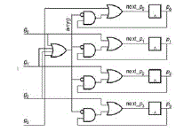
| Figure 2.3 shows the architecture of round robin arbitration which operates on the principle that a request which was just served should have the lowest priority on the next round of arbitration. Arbiter controls the arbitration of the ports and resolves contention problem. It keeps the updated status of all the ports and knows which ports are free and which ports are communicating with each other. Packets with the same priority and destined for the same output port are scheduled with a Round-Robin Arbiter. Supposing in a given period of time, there was many input ports request the same output or resource, the arbiter is in charge of processing the priorities among many different request inputs. The arbiter will release the output port which is connected to the crossbar once thelast packet has finished transmission. |
| So that other waiting packets could use the output by the arbitration of arbiter. A round-robin arbiter operates on the principle that a request which was just served should have the lowest priority on the next round of arbitration. Depending upon the control logic arbiter generates select lines for multiplexer based crossbar and read or write signal for FIFO buffer. Contention resolution is an important task of arbiter. If two or more resources are sending data to one destination at same time then there is contention for destination. This contentioncan be resolved by assigning priorities to the resources based on different scheduling algorithms. |
III PROPOSED ROUTER ARCHITECTURE
|
3.1 INTRODUCTION
|
| In packet switching the data transfers in the form of packets between cooperating routers and independent routing decision is taken. The store and forward flow mechanism is best because it does not reserve channels and thus does not lead to idle physical channels The arbiter is of rotating priority scheme so that every channel once get chance to transfer its data. In this router both input and output buffering is used so that congestion can be avoided at both sides. A router is a device that forwards data packets across computer networks. Routers perform the data “traffic direction" functions on the Internet. |
| A router is a microprocessor-controlled device that is connected to two or more data lines from different networks. When a data packet comes in on one of the lines, the router reads the address information in the packet to determine its ultimate destination. Then, using information in its routing table, it directs the packet to the next network on its journey. Data packet moves in to the input channel of one port of router by which it is forwarded to the output channel of other port. |
| Each input channel and output channel has its own decoding logic which increases the performance of the router. Buffers are present at all ports to store the data temporarily. The buffering method used here is store and forward. Control logic is present to make arbitration decisions. Thus communication is established between input and output ports. According to the destination path of data packet, control bit lines of FSM are set. The movement of data from source to destination is called switching mechanism. The packet switching mechanism is used here, in which the flit size is 8 bits .Thus the packet size varies from 0 bits to 8 bits. |
3.2 ROUTER STRUCTURE
|
| In the proposed system packet switching network is used.The PEs andIPs can be connected directly to any side of a router. Therefore, there is no specific connection port for a PE or IP.Three port networks are used as a router. |
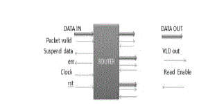
| Fig 3.1 shows the structure of proposed router which consists of data in, packet valid, suspend data, clock, reset, error,data out, valid out, and read enable. Based on the packet valid, the data is sent into the router. |
3.3 BLOCK DIAGRAM OF ADDRESS BASED PACKET SWITCHING
|
| METHOD |
| Fig 3.2 shows the block diagram of the proposed address based packet switching method. In this the packet is sent to the FSM and FIFO block. Then the corresponding operations are done. Finally the packets are routed to the respective output channels. |
3.4 ROUTER ELEMENTS
|
| FIFO |
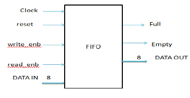
| In the FIFO (First In First Out), the inputs are stored and forwarded. So this method is also called as store and forward technique. |
| FSM |
| Fig 3.4 shows the FSM Block. It defines the state. Initially the header is fixed along with the address followed by the data.For example, to route the data for the third output channel, the enable 3 pin is selected, then the data is sent. Packet valid line has its importance during traffic conditions. If the desired channel is busy, FSM makes the packet valid to zero and no data will be sent. Similarly packets are sent to the desired channel only when the packet valid is high. |
SYNCHRONIZER
|
| The synchronizer is used to synchronize the inputs with the outputs. It is also used to check whether the correct data is received at the output side. For example, if there is fifth data in the FSM means the synchronizer will check that the FIFO has sent the fifth data. |
ERROR CHECKING UNIT
|
| For error checking we use parity generator. In our proposed system even parity is used. In order to check and correct the error, the sender may inform the receiver which kind of parity is used. |
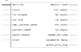
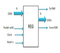
| Fig 3.5contains status, data and parity registers required by router. All the registers in this module are latched on rising edge of the clock. |
3.5 PROPOSED ROUTER PACKET FORMAT
|
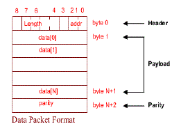
| In the proposed router packet format, it is designed with the help of parity. In every packet, 64 bytes of data is sent. Here error can also be found and can be corrected. |
| Fig 3.6 shows the packet format of the proposed system. In this, the last two bits are the address field and the remaining bits are the length of data. This forms the header of the packet format. The payload consists of 64 bytes of data. In this method, parity is separately defined. The length of the data is XORed with the accumulator input and this follows for the entire payload. Then the whole packet is sent. Based on the parity given, the error can be found. |
3.6 ROUTER INPUT PROTOCOL
|
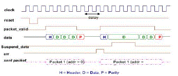
| Router input protocol defines how the packet has been sent to the channel or a buffer.Fig. 3.7reveals the significance of err line and suspend line in the router input protocol. The err line is made high in case of any error have been occurred. During the clock input, the data is sent only when the packet_valid line and the reset is enabled. When the same data is sent again, the suspend line is made high which ceases the transmission of data. At the same time, err line is made high to indicate the transmission of same data. |
3.7 ROUTER OUTPUT PROTOCOL
|
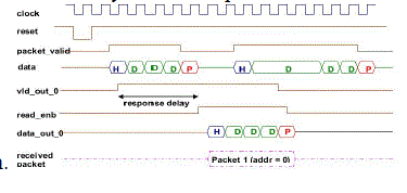
| The clock is given and the reset is set high. In the output protocol, the data can be received only when the status of read enable line is high irrespective of the status of valid out line. Based on the clock, reset, packet valid, the same packet can be received at the output. The data will be sent only when the packet valid status shows it is Fig 3.8 reveals the router output protocol structure. In this, the same output packet is received which was sent at the input side. |
3.8 SWITCHING TECHNIQUE
|
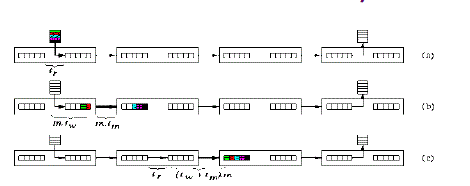
| Store and forward switching technique is used in the proposed system. In this technique, every packet is individually routed from the source to the destination. One step of the SF switching is called hop. It consists of copying the whole packet from one output buffer to the next input buffer. Routing decisions are made by each intermediate router only after the whole packet was completely buffered in its input buffer. |
| (a) Routing decision is being made in the first router. |
| (b) The packet is performing the first hop to the second router after has been copied to the output buffer of the first router. |
| (c) The whole packet after the second hop. |
| This technique is advantageous, when messages are short and frequent, since one transmission makes busy at most one channel from the whole path. |
3.9 FLOW CHART
|
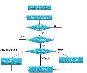
| Fig. 3.10 shows the flow diagram for the transmission of data. The source or the message is first splitted into packets. If the incoming packet is a valid one, then it is further given to the error checking unit where the error has been detected. The data packet containing error will be again splitted into packets and checks whether it is valid. The error free data packet will be routed to the destination considering three different states of affair.They are as follows. |
| 1) If there is no liability,the packets will be routed to the destination using the shortest path. |
| 2) If any failure occurs making the shortest path unapproachable, the router selects an alternate path in order to route the packets. |
| 3) In case of traffic during the function, router will select a path which is having less traffic |
IV SIMULATED RESULTS & DISCUSSION
|
4.1 COMPARISONS
|
| The emulations of round robin arbiter and packet switching are implemented on FPGA platform. Initially, we set different numbers of request inputs. We get the statistics about the resource utilization, throughput and power consumption of the two different arbitration mechanisms. Once the packets from the virtual channel of the input simultaneously request the crossbar switch, the number of the request inputs of arbiter increased. But our proposed system consists of packets having 64 bytes to be transmitted for one clock cycle |
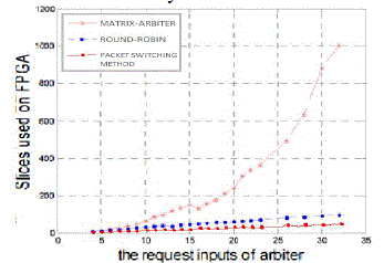
| Fig. 4.1 shows that the matrix arbiter and Round robin arbiter cost similar resource when there are a few requests; nearly about 100 slices are consumed. When the number of input requests increases, Matrix-arbiter will employ abundant resource compared to the round robin method. The proposed system consumes much less resources than the previous methods. When the request inputs approach 32, the Matrix-arbiter will utilize 1003 slices, the Round-robin arbiter just uses 98 slices while the switching technique uses around 50 slices. |
4.2 POWER ANALYSIS
|
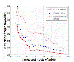
| Finally, we analyze and compare the power consumption of the two mechanisms. In Fig 4.2, we can see that the power consumption will increase as the number of inputs is increasing. The graph shows that the packet switching method consumes higher power than round-robin arbiter. In the design of our proposed scheme, we should make a trade-off among the resource, area, delay and power consumption, and choose suitable mechanism according to that. |
V CONCLUSION
|
| The proposed switching technique fulfilled the requirement of implementing a low area and low power communication path for on-chip networks. In this paper, two mechanisms such as round robin arbiter method and address based packet switching method are designed implemented on FPGA platform. Our proposed system is analyzed in terms of power and area by comparing with the existing scheme. The analysis shows that the arbiter which is designed based on address based the packet switching is having less area and power compared with the existing round-robin and conventional matrix arbiter method. |
Tables at a glance
|
 |
| Table 1 |
|
Figures at a glance
|
 |
 |
 |
 |
| Figure 1 |
Figure 2 |
Figure 3 |
Figure 4 |
 |
 |
 |
 |
| Figure 5 |
Figure 6 |
Figure 7 |
Figure 8 |
 |
 |
 |
 |
| Figure 9 |
Figure 10 |
Figure 11 |
Figure 12 |
 |
 |
 |
 |
| Figure 13 |
Figure 14 |
Figure 15 |
Figure 16 |
|
| |
References
|
- Cedric Killian, Camel Tanougast, FabriceMonteiro, and AbbasDandache, “Smart reliable network- on-chip”, IEEE Trans. VeryLarge Scale Integr. (VLSI) Syst.,Feb. 2013.
- A. Ejlali, B. Al-Hashimi, P. Rosinger, S. Miremadi, and L. Benini,“Performability/energy tradeoff in error-control schemes for on-chipnetworks,” IEEE Trans. Very Large Scale Integr. (VLSI)Syst., vol. 18, no. 1, pp. 1–14, Jan. 2010.
- M. Hosseinabady, M. Kakoee, J. Mathew, and D. Pradhan, “Lowlatency and energy efficientscalable architecture for massive NoCsusing generalized de Bruijn graph,” IEEE Trans. Very Large ScaleIntegr. (VLSI) Syst., vol. 19, no. 8, pp. 1469–1480, Aug. 2011.
- K. Sekar, K. Lahiri, A. Raghunathan, and S. Dey, “Dynamicallyconfig- urable bus topologies for high-performance on-chipcommunication,” IEEE Trans. Very Large Scale Integr. (VLSI)Syst.,vol. 16, no. 10, pp. 1413–1426, Oct. 2008.
- SuyogK.Dahule, Dr. M.A.Gaikwad, “Design and analysis of matrixarbiter for NoC architecture”, International Journal of AdvancedResearch in Computer Science and Electronics EngineeringVolume 1, Issue 5, July 2012.
|