Keywords
|
| Multi Level Inverter (MLI), Shunt Active Power Filter(APF), Peak Detection Method. |
INTRODUCTION
|
| Use of Photo voltaic systems for meeting power crisis has became general interest of system engineers in these days. PV systems supply real power from PV cells and demands reactive and Harmonic power simultaneously through power electronic converters thereby imposes power quality threats on the whole system. Effective power quality improvement methods to maintain the Quality of power is therefore became necessary. Many research efforts have been reported in present days to improve the power quality of PV systems. Usage of Shunt Active Power Filter (SAPF) is a solution for these problems and is responsible for compensation of harmonics and correction of the power factor of the system. Shunt APF operate as controlled current sources injecting current harmonic components to the power distribution system. The main control objective of SAPF consists of generation of reference current wave form for each phase and driving the inverter by generating gating signals to track this reference wave form. Singh et al. [10] have presented a review on classification of active filters for power quality improvement based on converter type, topology and the number of phases. |
| The multilevel Inverters produce a stepped output voltage waveform from several lower dc voltage sources. By the use of MLIs the switching losses and voltage stress on power electronic devices can be considerably reduced because the power semiconductor devices can be made to operate at low voltages compared to the conventional two level converters. The output voltage provided by MLIs has small voltage steps, that results in good power quality and lowharmonic components. Multilevel Inverters have obtained more and more attention in recent years and new topologies with a wide variety of control strategies have been developed. In this paper a three level neutral point clamped (NPC) or diode clamped MLI is used for Active Power Filter. |
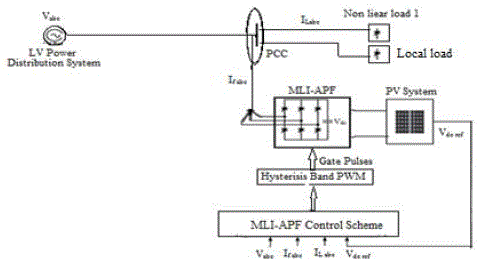
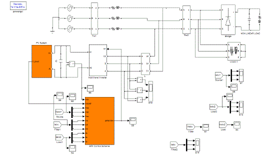
| The system considered in this paper is shown in Fig2.1 and consists of a PV based DG system, synchronized with the grid and supplying local load as well. The PV cell is modeled with reasonable accuracy. The control algorithms are established to 1) control the converter dc-link voltage to extract the maximum power from the PV system, 2) generate the reference current for the MLI-APF to compensate the harmonics and regulate the power factor of the system. |
| RELATED WORK: The main objective of the SAPF is Generation of reference currents for which many strategies are available in literature. The mostly used instantaneous p-q theory can provide an instantaneous and accurate reference compensating current [4,5] but suffers from the requirement of reference frame transformation from a-b-c axes to d–q axis. The Synchronous Reference Frame (SRF) strategy [6] only computes the sinusoidal fundamental components of the load currents; the reactive power compensation and a zero neutral current thus cannot be achieved if the load imbalance at the fundamental frequency occurs. A phase-locked loop (PLL) per each phase must be used. Grady et al. [16] have presented a survey of active power line conditioning methodologies with a list of the advantages and limitations of each one. Cavallini and Montanari [17] have proposed the unity power factor strategy known as classic strategy in which conditions the line currents to fit the voltage waveform, provides line current RMS values always lower than those obtained by keeping the instantaneous real power equal to its mean value. Chang and Shree [18] have proposed a simple and efficient compensation strategy that is suitable for three-phase shunt active power filters without reference-frame transformation requirement. In addition to these there are several other techniques such as extraction of load current RMS component[7], indirect current control [8], algorithm based on the real component of fundamental load current (I cosF) [9] etc., |
| To achieve full compensation of both reactive power and harmonic currents of the load, this paper presents a simple method to determine the SAPF reference compensation currents using dc voltage PI controller, source voltages and source currents. This method does not require any reference frame transformations. Hysteresis band current control PWM strategy is used to drive current controlled voltage source inverter (CC-VSI). |
| Modeling of the PV systems has been addressed by many [11-14].Prominently addressed issue in these systems is Maximum Power Point tracking (MPPT). Soft computing based MPPT techniques are developed in [19-20], but their analysis is with only dc/dc converters. In practice,integration with ac systems and the ac loads are very much common, even in the domestic applications, which are not addressed. In [15], right from 1968, total 19 MPPT algorithms have been reviewed. Among the different MPPT techniques, this paper uses perturb and observe (P&O)/hill climbing methods owing to their simplicity, low cost and easy implementation. |
| Previous work [1] has addressed the problems of compensating for harmonics and reactive power of the system. To achieve further performance improvement, this paper now explores the use of multilevel converter topologies in a similar context, since such converters are known to achieve an improved harmonic performance. |
| The contents of this paper are organized as follows: Section II describes the structure of the PV system considered along with PV generator modeling and MPPT control algorithm. Section III describes control scheme of SAPF and generation of control signals by proposed Peak detection method of controlling SAPF and in Section IV description of Multi Level Inverter based APF is presented. Simulation results and discussions are given for different test conditions in section V. Section VI concludes this paper. |
PV SYSTEM
|
| Among the various possibilities of DGs, photovoltaic (PV) systems have drawn prominent attention In spite of their high cost and poor conversion efficiency due to the following merit list |
| (i) It requires less time to install and start up new unit for generation. |
| (ii) It has no rotating parts, hence no noise, no maintenance and long life with less maintenance. |
| (iii) Solar energy is abundantly available on earth. |
| (iv) This energy source is non-polluting and available continuously free of cost. |
| PhotoVoltaic arrays are widely used now-a-days in medium sized grid with domestic utilities. Latest developments in the PV system topology is single stage PV system which are simpler, economical and more efficient than the two stage system. The Schematic diagram of the single stage system considered in this paper is shown in fig2.1 with its basic controls. Active Power Filter working as ac/dc converter synthesizes the ac voltage with available DC voltage from PV cells. Control signals for Hysterisis band controller will be derived from Peak detection controller. Peak detection control is used for Active power Filter to generate reference currents for harmonics suppression and power factor maintenance. This controller also tuned for the extraction of MPPT of PV system. Thus the APF which is main constituent of the proposed system and is responsible for (i) connecting the PV cells to the grid (ii) maintaining MPPT of the PV system (iii) maintaining power quality by eliminating harmonics and correcting power factor of the whole system |
Modelling of the PV Generator
|
| A more approximated yet relatively accurate model for PV Generator was proposed in [2]. The equivalent circuit with current source representing the photo current (Iph ), a diode, a series resistance to account for internal resistance to the current flow and a parallel resistance to consider the leakage current, is considered in this model. The same model has been considered for analysis in this paper. According to this model, for a PV panel, with Ns number of series cells and Np number of parallel cells, the output current can be given by (2.1)[1] |
 |
| Where I pv output current of the PV array, Vdc is the output voltage and Tc is working temperature of the cell, other parameters are: |
| Np and N s is Number of parallel and series cells, ISC is Cell’s short circuit current, I rs is Cell reverse saturation current, qis Charge of an electron, k is Boltzmann’s constant, Ideality factor is A, Cell’s reference temp is Tref and Short circuit current temperature coefficient of cell is KI |
| The photo current, Iph and the power output, Ppv of the PV generator are given as (2.2)[2] |
 |
| The PV array with Ns and Np cells is modeled using the basic blocks in MATLAB/SIMULINK. For the dc/ac converter of Fig2.1, universal bridge block is considered but its PWM pulses are generated according to the control algorithm explained in the section 3.1 |
P&O MPPT algorithm
|
| The power output of the PVcell is nonlilearly dependent on the operating voltage as depected in Fig.2.2. For a perticular incident insolation and temperature there is only one unique operating voltage, at which the PV panel needs to be operated to extract maximum power and hence the maximum efficiency from it. Thus, a suitable mechanism which is capable of detecting this voltage is necessary. This objective is carried out by MPPT system. In the Fig.2.2, 100% of insolation corresponds to 1000W/m2 [2] |
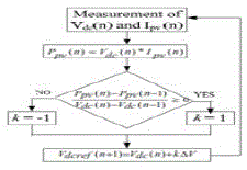
| In Perturb & Observe(P&O)algorithm the voltage is varied in both positive and negative directions with a small value, known as perturbation ΔV. At last, the system will settle at a voltage that corresponds to the maximum power. The P&O algorithm changes the voltage at constant sampling rate to track the maximum power irrespective of change in operating conditions. Fig.2.3 shows the flow chart of P&O algorithm. Even though P&O has the disadvantages of getting confused over rapidly changing atmospheric conditions and oscillations around MPP in the steady state, it is easy to implement and requires less hardware, with reasonable accuracy. Hence, a variant of P&O, known as dp/dv algorithm [2] is used for the MPPT to compare with the performance of proposed algorithm in this paper. |
CONTROL SCHEME OF SAPF
|
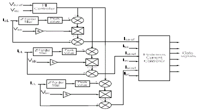
| General block diagram showing control scheme of a shunt active power filter is shown in Fig. 3.1. The reference currents that are to be tracked by MLAPF to compensate the load current harmonics, reactive power, are generated by peak detection method. Well tuned PI controller unit keeps the total dc bus voltage constant and equal to a given reference value which in his case is operating voltage of PV system according to MPPT. Small amount of power required to meet the losses in the inverter circuit are taken into consideration by the dc voltage control unit. |
Peak detection Method with PI Controller
|
| In this control strategy, the required fundamental component of the distorted load current is extracted by filtering. The band-pass filter is used and tuned at the fundamental frequency (50 Hz), so that the gain attenuation introduced in the filter output signal is zero and the phase-shift angle is 1800. The output current of the filter is thus equal to the fundamental component of the load current but phase shifted by 1800. In order to provide the reactive power required by the load, the current signal obtained from the filter Il1 is synchronized with the respective phase to- neutral source voltage so that the inverter ac output current is forced to lead the respective inverter output voltage, thereby transfering the required reactive power. During the operation inverter consumes small amount of real power to meet the switching losses and to keep dc voltage constant. The reference current wave form must also take this component into consideration. Thus the sinusoidal reference current waveform obtained from control strategy has the components corresponding to the fundamental component of the load current, the error signal obtained from the dc voltage control unit. In this way, the current signal allows the inverter to supply the current harmonic components, the reactive power required by the load, and to absorb the small amount of active power necessary to cover the switching losses and to keep the dc voltage constant. Similar scheme is necessary for each phase. The control diagram is shown in fig 3.2 |
Design of Hysteresis Current Controller for PWM Switching
|
| The active filter is comprised of three-phase IGBT based current controlled VSI bridge. The upper device and the lower device in one phase leg of VSI are switched in complementary manner. |
| Ideal compensation requires the mains current to be sinusoidal and in phase with the source voltage, irrespective of the load current nature. The source reference currents, after compensation, can be given as |
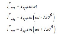 |
| where Isp is the amplitude of the desired source current, while the phase angle can be obtained from the source voltages. Hence, the waveform and phases of the source currents are known, and only the magnitudes of the source currents need to be determined. |
MULTI LEVEL INVERTER BASED ACTIVE POWER FILTER
|
| Recent trend is to focus on the multi-level inverter topologies, which significantly improve the output waveform spectrum of the inverter. Therefore, the use of bulky and expensive multi-pulse transformers can be avoided, resulting in reduced stress of the power semiconductor devices, substantially smaller filters and consequently, a cost reduction of the system . The main operating concept of these inverters is to divide the DC link potential into multiple sections, so that each phase leg can switch between multiple voltage levels (rather than the two voltages only of a two-level inverter). This reduces the burden on the switches and there by switching losses. |
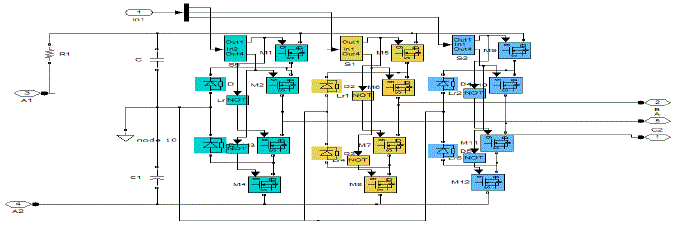
| All the four basic topologies of MLIs have their own strengths and weaknesses. In this paper a 3 level diode clamped MLI topology is used that can obtain the multiple voltage levels with a low cost string of DC capacitors. However this is done with an expense of fluctuations in capacitor voltages. This problem can somehow mitigated by using low levels. For this reason the analysis is limited to 3-level. The simulink model of 3level MLI used is shown in fig.4.1 below. |
SIMULATION RESULTS AND DISCUSSION
|
| The SIMULINK model of the system considered is shown in figure.5.1 |
| Following are the system parameters considered for the study of SAPF with proposed peak detection method for PI controller. Vs = 220 V (Peak), f = 50 Hz, Rs= 0.1 Ω, Ls= 0.03mH, Lf = 0.01 mH, In case of PI the gains chosen are kp= 1 and ki = 9. A Diode bridge is used as non linear load which feeds power to an RL load. A local RL load of R=10 Ω and L=20mH is also considered. |
A. Operating characteristics of PV generator
|
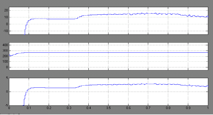
| Fig. 5.1 Shows Operating Characteristics of PV generator which consists of Current injected, Operating votage and power fed at PCC by PV generator. Fig.5.3 shows the operating voltage of PV generator when connected in system. |
| The nonlinear operating characteristics of the PV generator obtained by operating the considered PV cell for different insolations at stand still is shown in fig5.2 below which suggests that for Maximum power extraction at different insolations, the operating voltage is somewhere between 200&250V. |
| It is evident from the fig.5.1(b) that the PV system is operating at a voltage close to that corresponding to MPPT as obtained from Fig.5.2. |
B.Performace Results of Active Power Filter
|
| The performance results of two level and three level shunt active power filter are presented in Fig.6 below. Both load current and source current harmonic distortion are improved in three level APF. The filter currents and voltages are smoothened as shown in fig. which reduces the burden on filter operation. |
| The Load current and source currents of three phases of two level SAPF are shown in fig 5.3 below. Inspite of the nonlinearities in load currents, due to the presence of nonlinear load, the source currents are sinusoidal in nature due to the the operation of SAPF. |
| Three phase filter voltages and three phase currents injected by two level inverter in compensating the harmonics and making source currents sinusoidal are shown in fig.5.4 . It can be observed from these that the filter voltages are of large step size and filter currents are rich in harmonics compared to three level SAPF. Thus they impose more burden on the operation of SAPF eventually resulting in losses in the converter. |
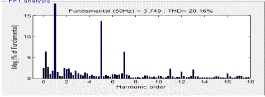
| The FFT analysis is performed for source and load currents of the system and are presented in Fig.5.5 and 5.6 respectively. The source current THD is reduced to 1.32% when compared to 20.16% of Load current. |
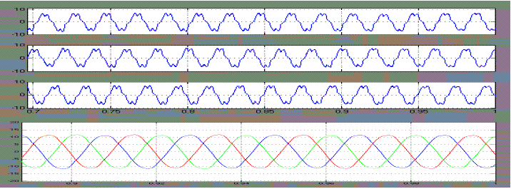
| The performance results of the MLI(three level) SAPF are presented in the fallowing figures. Fig.5.7 shows the Load and source currents of three phases. It is clear from these that when compared to two level SAPF both of these currents are improved and harmonic contents are considerably reduced. |
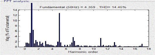
| The THD analysis of these source and load currents are presented in the fig.5.8and 5.9 below. The THD percentage of these currents are considerably reduced to1.17% and 14.45% for source and load currents respectively. |
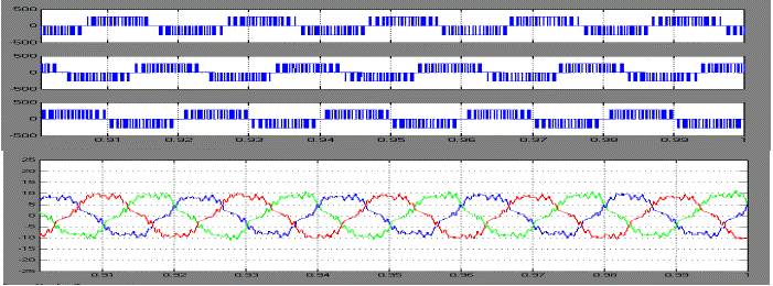
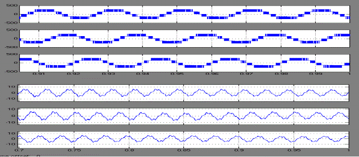
| The operating voltages and injected currents of Three level APF are presented in fig.5.10. when compared to two level APF, the filter voltages are of small step and smoothened. With this the voltage stress in the semi conductor devices is reduced. The injected filter currents are also smoothened compared to two level APF which reduces burden and switching losses in the VSI converter. |
CONCLUSION
|
| Proposed system eliminates the usage of Separate converters for connection of PV cells and Compensation of current harmonics. To make a move towards the improvement of harmonic performance, the existing two level converter of PV system has been replaced by Multi Level Inverter. The results obtained reveals that for the same operating conditions of PV system the THD of load and source currents are improved considerably in three level converter compared to two level. The filter voltages are also smoothened which reduces the burden on the operation of filter. |
Figures at a glance
|
 |
 |
 |
 |
| Figure 2a |
Figure 2b |
Figure 2c |
Figure 2d |
|
 |
 |
 |
 |
| Figure 3 |
Figure 4 |
Figure 5a |
Figure 5b |
|
 |
 |
 |
 |
| Figure 5c |
Figure 5d |
Figure 5e |
Figure 5f |
|
 |
 |
 |
 |
| Figure 5g |
Figure 5h |
Figure 5i |
Figure 5 |
|
References
|
- Ram Kumar,P.V., Surya Kalavathi, M., “Power Quality Improvement in a grid connected Single stage pv generating system by integratingShunt active filter for both connection of Pv cells and power quality improvement” i-manager’s Journal on Power Systems Engineering, Vol. 2No. 1, pp.1-10, February - April 2014
- Mishra, S., Senior Member, IEEE and Sekhar,P.C., “Sliding Mode Based Feedback Linearizing Controller for a PV System to Improve thePerformance under Grid Frequency Variation”IEEE International conference on energy,automation and signal(ICEAS), pp1-7,December2011,
- Ram Kumar,P.V., Surya Kalavathi,M.,, “A Simple Control Algorithm For Three-Phase Shunt Active Power Filter For Reactive Power AndCurrent Harmonic Compensation”, International Journal of Electrical Engineering(IJEE) , International Research Publications, Volume 6,pp. 473-483, Number 4 (2013),
- H. Akagi, Y. Kanzawa, and A. Nabae “Instantaneous reactive power compensators comprising switching devices without energyComponents” IEEE Transactions on Industrial Applications, Vol. 20, No. 3, pp. 625–630, 1984
- H. Akagi, E. Watanabe, M. Aredes “Instantaneous Power Theory and Applications to Power Conditioning: Wiley- IEEE Press, 2007.
- S. Bhattacharya and D. Divan, “Synchronous frame based controller implementation for a hybrid series active filter system”, IEEE Ind.Applicat. Soc. Annu. Meeting, vol. 3,pp.2531-2540, 1995.
- Cavallini and G. C. Montanari “Compensation Strategies for Shunt Active-Filter Control” IEEE Transactions on Power Electronics, Vol.9,No. 6, pp. 587- 593, November 1994.
- Bhim Singh, and Vishal Verma “An Indirect Current Control of Hybrid Power Filter for Varying Loads” IEEE Transactions on PowerDelivery,Vol. 21, No. 1, pp. 178- 184, January 2006.
- G. Bhuvaneswari, and Manjula G. Nair “Design, Simulation, and Analog Circuit Implementation of a Three-Phase Shunt Active Filter UsingtheIcosΦ Algorithm” IEEE Transactions on Power Delivery, Vol. 23, No. 2, pp. 1222 – 1235, April 2008.
- Bhim Singh, Kamal Al-Haddad, and Ambrish Chandra “A Review of Active Filters for Power Quality Improvement” IEEE Transactions onIndustrial Electronics, Vol. 46, No. 5, pp. 60 – 71, October 1999.
- J. A. Gow and C. D. Manning, “Development of a photovoltaic array model for use in power-electronics simulation studies,” IEEProceedings- Electric Power Applications, vol. 146, no. 2, pp.193-199, 1999.
- C. C. Hua and C. M. Shen, “Study of maximum power tracking techniques and control of dc-dc converters for photovoltaic power system,”Proceedings of 29th annual IEEE Power Electronics Specialists Conference, vol. 1, pp. 86-93, 1998.
- O. Wasynczuk, “Modeling and dynamic performance of a line commutated photovoltaic inverter system,” IEEE Transactions on EnergyConversion, vol. 4, no. 3, pp. 337-343, 1989.
- K. H. Hussein, I. Muta, T. Hoshino, and M. Osakada, “Maximum photovoltaic power tracking: an algorithm for rapidly changingatmospheric conditions,” IEE Proceedings of Generation, Transmission and Distribution, vol. 142, no. 1, pp. 953-959, 2005.
- T. Esram and P. L. Chapman, “Comparison of photovoltaic array maximum power point tracking techniques,” IEEE Trans. Energy Convers.,vol. 22, no. 2, pp. 434–449, Jun. 2007.
- W. M. Grady, M. J. Samotyj and A. H. Noyola “Survey of Active Power Line Conditioning Methodologies” IEEETransactionon Power Delivery, Vol. 5, No. 3, pp. 1536- 1542, July 1990.
- A. Cavallini and G. C. Montanari “Compensation Strategies for Shunt Active -Filter Control” IEEE Transactions on Power Electronics, Vol.9, No. 6, pp. 587- 593, November 1994.
- G. W. Chang, and T. C. Shee “A Novel Reference Compensation Current Strategy for Shunt Active Power Filter Control” IEEETransactions on Power Delivery, Vol. 19, No. 4, pp. 1751 – 1758, October 2004.
- M.Veerachary,T.Senjyu and K.Uezato, “Voltage-Based Maximum Power Point Tracking Control of PV System,” IEEE Trans. on AerospaceandElectronic Systems, Vol.38, No.1, pp.262-270, Jan. 2002.
- M.Veerachary,T.Senjyu and K.Uezato, “Neural-Network-Based Maximum-Power-Point Tracking of Coupled-Inductor Interleaved-Boost-Converter-Supplied PV System Using Fuzzy Controller,” IEEE Trans. onIndustrial Electronics, Vol. 50, No. 4, pp. 749-758, Aug.2003.
|