Keywords
|
| Supercapacitor, SEPIC converter, PV cells |
INTRODUCTION
|
| With the ever-increasing demand for low-cost energy and growing concern about environmental issues, PV based systems are being increasingly employed in diverse applications both at domestic and commercial levels. While a wide variety of harvesting modalities are now feasible, solar energy harvesting through photovoltaic (PV) conversion provides the highest power density, which makes it the preferred choice to power an embedded system that consumes several mille watt using a reasonably small harvesting module. The growing emphasis on energy saving. PV being a major energy source enables the dc loads to be connected directly to the dc bus. Photovoltaic systems can be broadly classified into stand-alone system and grid-connected system. The stand-alone system is widely used in remote places where access to electricity is not viable. The stand-alone configuration can provide a well-regulated load voltage, but the reliability of power supply cannot be guaranteed. Storage batteries are widely used to improve the reliability of the stand-alone system. The integration of a PV system to the grid is rapidly increasing due to the improvement in the power electronics technology. In grid-connected PV systems (gcpvs), the generated PV power is fed to the grid, or it supplies the linear and nonlinear loads connected at the ac side. In some hybrid systems[5] battery is used to compensate the mismatch between the generation and demand. |
CURRENT SCENARIO
|
| In developing countries, the demand for power is growing beyond the planner’s estimation, and the power grid is weak, and scheduled power outages throughout the year are common. In addition, there are also unscheduled short term outages which are random and frequent. Therefore, the grid-side inverter should operate in grid-tied mode and off-grid mode to supply uninterrupted power to the critical loads during power outages. A grid-connected PV system[1] involves a power source (PV array), a power sink (load), and two power sources/sink (utility and battery), and hence, a power flow management system is required to balance the power flow among these source. The load profile seen by the electrical grid is undergoing a notable change as these devices have to operate from a dc source. In some applications, a battery was connected directly in parallel with the dc bus. The size of the battery can be reduced. when a battery charger/discharger circuit is inserted between the dc bus and In developing countries, the demand for power is growing beyond the planner’s estimation, and the power grid is weak, and scheduled power outages throughout the year are common. In addition, there are also unscheduled short term outages which are random and frequent. Therefore, the grid-side inverter should operate in grid-tied mode and off-grid mode to supply uninterrupted power to the critical loads during power outages. A grid-connected PV system[1] involves a power source (PV array), a power sink (load), and two power sources/sink (utility and battery), and hence, a power flow management system is required to balance the power flow among these source. The load profile seen by the electrical grid is undergoing a notable change as these devices have to operate from a dc source. In some applications, a battery was connected directly in parallel with the dc bus. The size of the battery can be reduced. when a battery charger/discharger circuit is inserted between the dc bus and |
CHALLENGES FACED IN CURRENT
|
| When the solar radiation is less, the power quality is degraded as the total harmonic distortion (THD) of the line current is inversely proportional to the power injected into the grid. Furthermore, the disturbance in dc link voltage is reflected in PV array power, and the PV operating point shifts from the maximum power point (MPP). Hence, a fast regulation of dc link voltage is necessary to ensure constant dc voltage while simultaneously maintaining the THD of the current injected into the grid within the standard limit dc bus. The size of the battery can be reduced when a battery charger/discharger circuit is inserted. |
PROPOSED SYSTEM
|
| A simple and low cost way to extract and store energy from a PV source is to connect the solar panel directly to a battery with a diode. The main disadvantage of this solution is that the system does not always work in the optimal condition to convert the available solar energy. To improve the system performance, a controller can be added between the PV panel and the battery. Maximum power point tracking (MPPT) circuits differentiate themselves in the design of the power converting electronics and/or in the control strategy, but the charging of batteries in presence of fluctuating power sources remains an open issue. |
| This paper proposes a power management architecture that utilizes both super capacitor cells and a lithium battery as energy storages for a photovoltaic (PV). The super capacitor guarantees a longer lifetime in terms of charge cycles and has a large range of operating temperatures, but has the drawback of having low energy density and high cost. The lithium battery has higher energy density but requires an accurate charge profile to increase its lifetime, feature that cannot be easily obtained supplying the wireless node with a fluctuating source as the PV one. A Controller is added between the solar panel and the battery to improve the system performance. Sepic convertors allow output from convertors to be higher or lower than its input and allow the output to be non-inverted state with respect to input. The controller is usually a dc-dc converter and controls the input voltage or current another convertor is generally used as the output converter to step-up the voltage because of the low voltage of the super capacitor. Combining the two storages is possible to obtain good compromise in terms of energy density |
| A. functional block diagram |
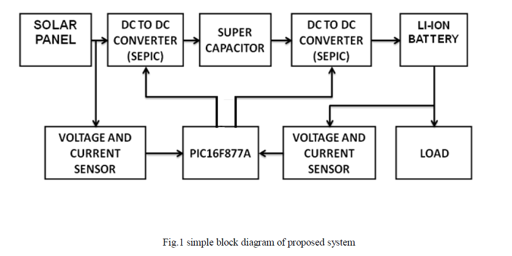 |
| Figure 1 shows the functional block diagram of the proposed system. A combination of two SEPIC converters is used across a supercapacitor. The two converters can be used for both step up and step down operation according to the supply and demand. Voltage and current are sensed at source and load sides and given to ADC of PIC controller, so that it suitable provide switching pulse to SEPIC converters through MOSFET switches |
| B. Circuit diagram |
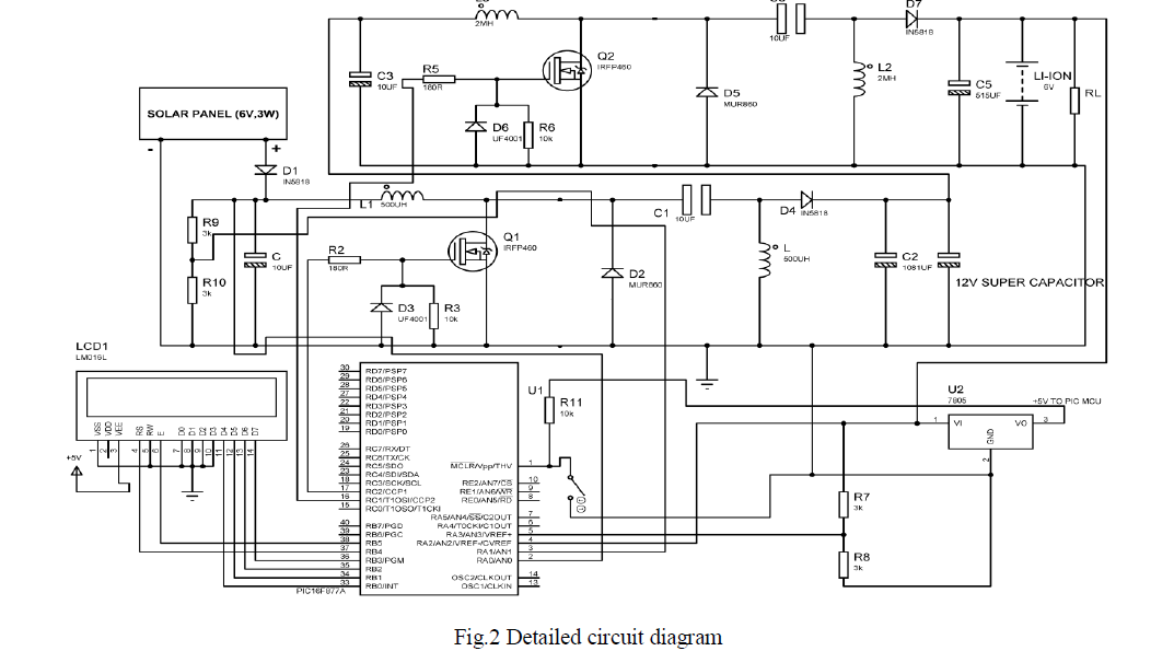 |
SUPER CAPACITOR
|
| A Super Capacitor is an electrochemical component that will lead electrical energy storage into a new dimension. Super Capacitor cells are able to fill the gap between capacitors and batteries by providing high power performance. A Supercapacitors’ strength is its ability to charge and discharge within seconds without damage. Super Capacitor performs in harsh environments reliably and maintenance free. The official naming of a Super Capacitor is Electric Double-Layer Capacitor (EDLC) under many different brand names such as Super capacitor, Pseudo capacitor Ultra capacitor. . Super capacitor cells are able to fill the gap between strength is its ability to charge and discharge within seconds without damage. |
| A. Working principle |
| Like an ordinary capacitor, a Super Capacitor has two plates that are separated by a dielectric. The differences are the plates are coated with activated carbon. Activated carbon is a very porous substance, having an enormous surface area enabling storage of much more electrical energy. The dielectric that separates the plates of a capacitor is an electrolyte. The electrolyte is a liquid that is electrically active. In a normal capacitor there is a dielectric separator that keeps the positive charges on one plate and negative charges on the other plate safely apart. A Super Capacitor the electrolyte is polarized by the charged plates. |
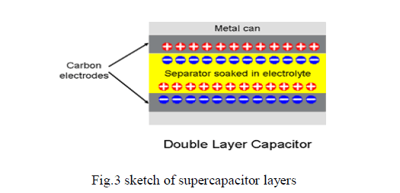 |
| The positive ions of the electrolyte are attracted by the negative charge of one plate; conversely, the negative ions by the positive charge of the other plate. This movement of the ions form a second charge, the double layer allows the Super Capacitor to store much more electrical energy providing a higher power performance. |
| Their cycle efficiency, which is defined as the ratio of the energy input to the energy output of an energy storage element, reaches almost 100%. The terminal voltage of a supercapacitor is a linear function of its state of charge, which is given by |
 |
| Where Ecap is the energy stored in the supercapacitor, and C is the capacitance. Ecap increases or decreases dynamically as charge or discharge operations are performed. The same is true for Vcap, whose variation is much higher than the terminal voltage of an ordinary battery, and therefore, the charger efficiency of a supercapacitor varies more significantly compared with that of a battery. |
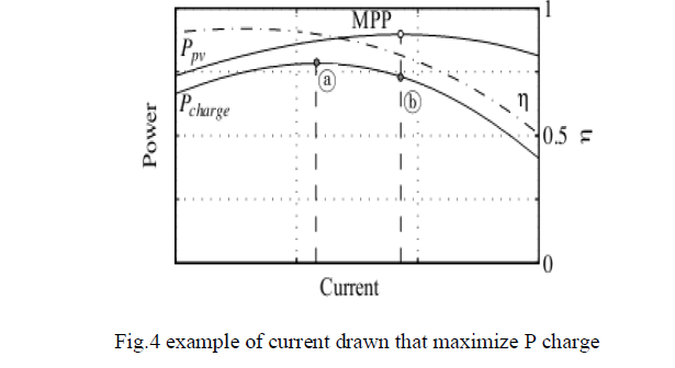 |
| MPPT is maximum power point tracker which indicates the point at which maximum power can be extracted from a solar cell.various studies have been carried out in finding an algorithm for MPPT[6].Conventional MPPT simply finds the operating point that result in maximum Ppv regardless of the charger efficiency at that point. In the figure 4, this point is b. In reality we are interested in maximizing Pcharge, which is achieved at point a in the figure 4. This is because at point a, although the current Ipv is offset from the current of the MPP, since efficiency is high enough, Pcharge at this point is larger than Pcharge at the MPP, i.e., point b. Consequently, MPPT and maximum efficiency tracking of the charger should be considered at the same time. Because efficiency is affected by both the PV module voltage and the supercapacitor voltage, we have to take the status of the supercapacitor into account when finding the optimal operating point that maximizes Pcharge. |
| B.Internal charge-distribution process after the first charging cycle. |
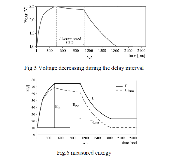 |
| Supercapacitors experience several charge-distribution processes with different time constants, even in isolated and disconnected state. This makes it difficult to identify the process that is responsible for voltage variations. After just being charged for a short period, a disconnected supercapacitor will exhibit a decreasing voltage. This decrease is mainly caused by a charge distribution within branches. Eform represents the energy content of the supercapacitor computed by measuring its output voltage and using the formula, |
 |
| While is obtained by measuring first the energy de-livered by the generator for the charging phase and then, during discharging, measuring the energy delivered to the load. The energy Ein is the total energy provided to the supercapacitor during charging, while Eout represents the total energy delivered by the supercapacitor during discharging. Notice that the supercapacitor does not behave as an ideal storage device as Ein is larger than Eout . Hence, we can define the cycle efficiency of the supercapacitor as |
| áüàcycle=Eout/Ein.100 ..... (3) |
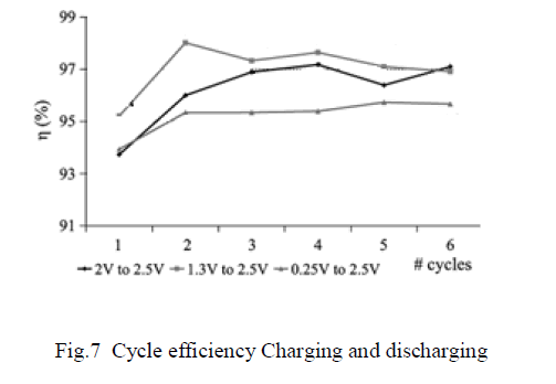 |
| An important phenomenon that accounts for the non ideality of the supercapacitor is the decrease of the supercapacitor voltage during the delay interval. No energy is extracted from the supercapacitor, and still, the voltage decreases. This is mainly caused by the charge-distribution process that, in the short term, is more important than leakage. Fortunately, this non ideal behaviour becomes less significant as the number of charging/discharging cycles increases, so becomes a more reliable estimator of the stored energy with errors that are lower than 10%. As a consequence with the increment of the number of cycles, the difference between Ein and Eout decreases. |
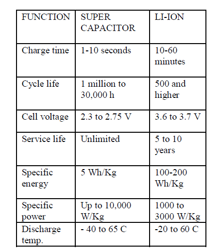
| C.Comparison between super capacitor and Li-ion battery |
 |
SEPIC CONVERTOR
|
| Single-ended primary-inductor converter (sepic) is a type of dc-dc convertor allowing the electrical potential at its output to be greater than, less than, or equal to that at its input; the output of the sepic is controlled by the duty cycle of the control transistor. A sepic is similar to a traditional buck-boost converter, but has advantages of having non-inverted output in which the output has the same voltage polarity as the input.Sepics are useful in applications in which a battery voltage can be above and below that of the regulator's intended output. |
| A. circuit diagram |
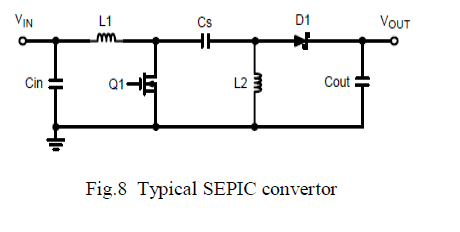
| Figure 8 shows a simple circuit diagram of a SEPIC converter, consisting of an input capacitor,Cin an output capacitor, Cout; coupled inductors L1 and L2, an AC coupling capacitor, Cs power MOSFET, Q1, and diode D1. |
 |
| B.working principle |
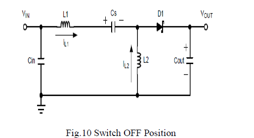
| When Q1 is on energy is being stored in L1 from the input and in L2 from Cs. When Q1 turns off, L1’s current continues to flow through Cs and D1, and into COUT and the load. Both COUT and Cs get recharged so that they can provide the load current and charge L2, respectively, when Q1 turns back on. |
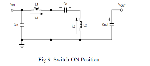 |
| When Q1 is off, the voltage across L2 must be VOUT. Since CIN is charged to VIN, the voltage across Q1 when Q1 is off is VIN + VOUT, so the voltage across L1 is VOUT. When Q1 is on, capacitor Cs, charged to VIN, is connected in parallel with L2, so the voltage across L2 is –VIN. The currents flowing through various circuit components are shown in Figure 10. |
 |
| Because the potential (voltage) across capacitor C1 may reverse direction every cycle, a non-polarized capacitor should be used. However, a polarized tantalum or electrolytic capacitor may be used in some cases, because the potential (voltage) across capacitor C1 will not change unless the switch is closed long enough for a half cycle of resonance with inductor L2, and by this time the current in inductor L1 could be quite large. |
| The capacitor CIN is required to reduce the effects of the parasitic inductance and internal resistance of the power supply. The boost/buck capabilities of the SEPIC are possible because of capacitor C1 and inductor L2. Inductor L1 and switch Q1 create a standard boost converter, which generates a voltage (VS1) that is higher than VIN, whose magnitude is determined by the duty cycle of the switch S1. |
| Since the average voltage across C1 is VIN, the output voltage (VO) is VS1 - VIN. If VS1 is less than double VIN, then the output voltage will be less than the input voltage. If VS1 is greater than double VIN, then the output voltage will be greater than the input voltage. The evolution of switched-power supplies can be seen by coupling the two inductors in a SEPIC converter together, which begins to resemble a Fly back converter, the most basic of the transformer-isolated SMPS topologies. |
DESIGN OF CONVERTERS`
|
| A. Inductor Selection |
 |
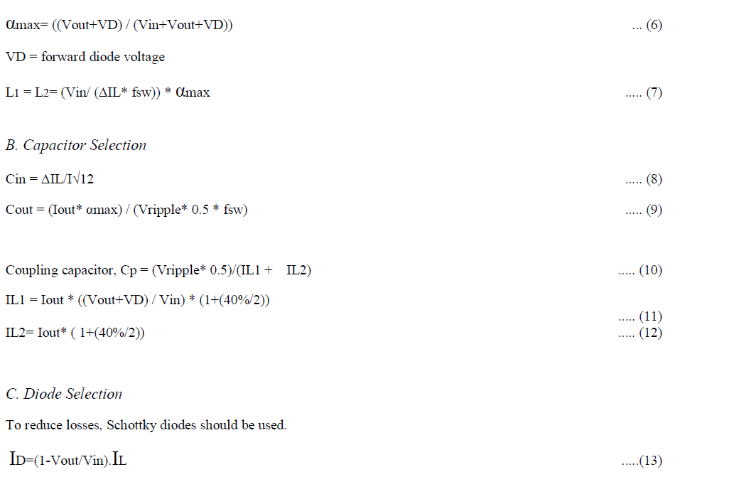 |
| The forward current rating needed is equal to the maximum output current. IOUT (max) = maximum output current necessary in the application Schottky diodes have a much higher peak current rating than average rating. Therefore the higher peak current in the system is not a problem. The other parameter that has to be checked is the power dissipation of the diode. |
| D.Snubber Circuit |
| RC snubber circuits are normally connected across a switching device to limit the dv/dt. A simple snubber uses a small resistor (R) in series with a small capacitor (C). This combination can be used to suppress the rapid rise in voltage across a mosfet, preventing the erroneous turn-on of the mosfet. It does this by limiting the rate of rise in voltage (dV/dt) across the mosfet to a value which will not trigger it. Let the minimum switching time constant is T = 1/20 KHz = 0.05 milli seconds |
| Hence the RC should satisfy this time constant i.e RC=0.05msec. Let C = 0.05uF, then R = 1 Kilo ohm. |
| E.Reliability and Efficiency |
| The voltage drop and switching time of diode D is critical to a SEPIC's reliability and efficiency. The diode's switching time needs to be extremely fast in order to not generate high voltage spikes across the inductors, which could cause damage to components. Inductors with lower series resistance allow less energy to be dissipated as heat, resulting in greater efficiency. |
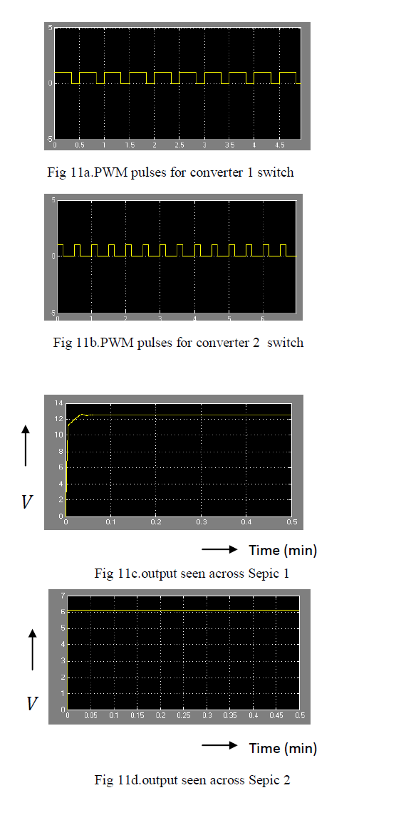
SIMULATION RESULTS FOR PROPOSED SYSTEM USING MATLAB
|
 |
CONCLUSION
|
| So, we have integrated super capacitor and li-ion battery which increase the life time of the battery and reduce the size of it. Also by introducing SEPIC converter we can control the system in a better way. We have demonstrated the model using MATLAB simulation. Also, by developing these kinds of projects we may be able to charge our DC loads like mobiles, laptop batteries instantly during power outages. Also, may be in near future we may develop stations which provides instant charging for cost using large solar array. |
ACKNOWLEDGMENT
|
| I am thankful to S.A.Engineering college for providing us full support to carry out this project. I also thank INEL POWER SYSTEMS, CHENNAI for providing technical help and support to let us do this project in their company. |
References
|
- Balasubramanian indurani,member,ieeeganesansaravanailango, and chilakapatinagamani,member,IEEE,”Control strategy for power flow management in a pv system supplying dc loads”, TRANSACTIONS ON INDUSTRIAL ELECTRONICS, VOL. 60,NO. 8, A UGUST 2013
- DarigaMeekhun,VincentBoitier,Jean-Marie DilhacStéphanePetibon, Corinne Alonso and Bruno Estibals”Buck converter design for photovoltaic generators with supercapacitor energy storage”, international conference on renewable energies and power quality, (icrepq’11) Las Palmas de Gran Canaria (Spain), 13th to 15th April, 2010
- Davide brunelli, clemensmoser”Design of a solar-harvesting circuit for batteryless embedded systems”. IEEE TRANSACTIONS ON CIRCUITS AND SYSTEMS—I:REGULAR PAPERS, VOL. 56, NO.11, NOVEMBER 2009
- Hichamfakham, di lu, brunofrancois, senior member,IEEE”Power control design of a battery charger in a hybrid active pv generator for load-following applications”Transaction on Industrial Electronics, Vol. 58, Iss. 1 , pp. 85-94, Jan. 2011, TIE-09-1370
- Teenajacob and arun electrical and electronics engineering.”Modeling of hybrid wind and photovoltaic energy system using a new converter topology”.An International Journal (EEEIJ) Vol.1, No.2, August 2012
- Younghyunkim, naehyuckchangseoul national university, koreayanzhiwang”Maximum power transfer tracking for a photovoltaic-supercapacitor system”
|