Keywords
|
| Reactive Power Compensation, Multi-objective Optimization, Evolutionary Algorithms, Particle Swarm Optimization and Comparison result. |
INTRODUCTION
|
| The stress on the transmission lines are increasing day by day. Because of the high cost involved and the restrictions in obtaining the Right of Way, it is preferable to enhance the performance of existing transmission system by installing Reactive Power Compensation rather than introducing new transmission lines. Reactive Power Compensation (RPC) is commonly addressed as a constrained Single-objective Optimization Problem (SOP). With this approach, an adequate location and size of shunt capacitor banks are found. |
| Optimal size and locations of RPC in Electric Power Systems is usually studied as constrained SOP where an objective function is a factor of transmission line losses only, subject to operational constrains, such as reliability and voltage profile. SOP Algorithms usually provide a unique optimal solution. |
| In this paper, the optimisation problem is formulated as a Multi-Objective Optimization Problem (MOP) including the system voltage deviation, the active power loss in transmission lines and cost of introducing RPC. Multi-objective Optimization independently and simultaneously optimizes several parameters turning most traditional constraints into new objective functions. This seems more natural for real world problems where choosing a threshold may seem arbitrary. The MOP has been solved by using optimization techniques namely Evolutionary Programming (EP) and Particle Swarm Optimization (PSO). The results of the two methods have been compared. |
MULTI-OBJECTIVE OPTIMIZATION PROBLEMS
|
| A general MOP includes a set of n decision variables, a set of k objective functions, and a set of m restrictions. Objective functions and restrictions are functions of decision variables. This can be expressed as: |
 |
 |
MATHEMATICAL FORMULATION
|
| The following assumptions are made in the formulation of the problem: |
| • Shunt-capacitor/reactor bank cost per MVAr is the same for all bus-bars of the power system. |
| • Power system is considered only at peak load. Based on these considerations, three objective functions Fi (to be minimized) have been identified. |
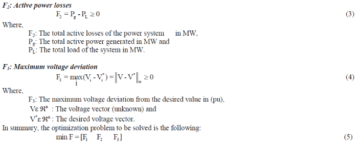
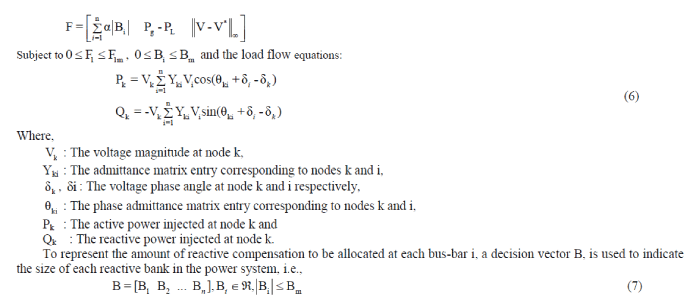
| F1 and F2 are related to investment and transmission losses, while F3 is related to quality of service. The objective functions are: |
 |
 |
 |
MULTI-OBJECTIVE REACTIVE POWER COMPENSATION USING EVOLUTIONARY PROGRAMMING
|
A. EVOLUTIONARY PROGRAMMING ALGORITHM
|
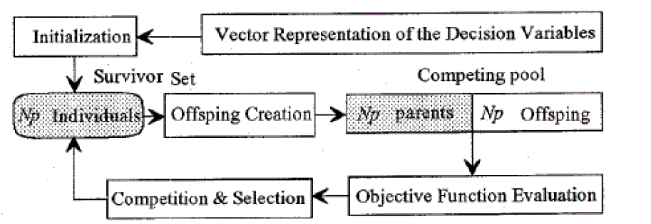
| More than 45 years ago, several researchers from US and Europe independently came up with the idea of mimicking the mechanism of biological evolution in order to develop powerful algorithms for optimization and adaptation problems. This set of algorithms is known as Evolutionary Algorithms (EA). One of the most commonly used evolutionary algorithms is EP. This technique was originally conceived by Fogel in 1960. The schematic diagram of the EP algorithm is depicted in figure 1. The general scheme of the EP follows the sequence below: |
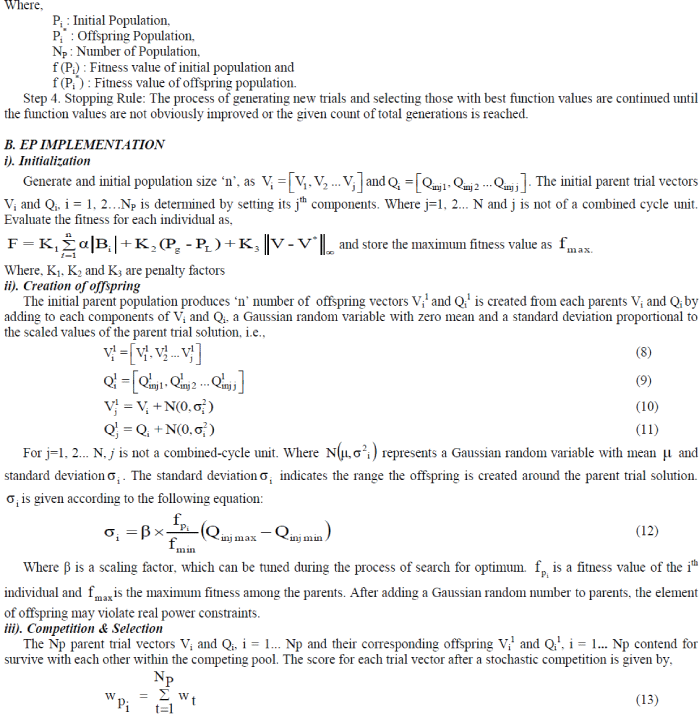
| Step 1. Initialization: An initial population of parent individuals Pi, i=1, …, NP, is selected randomly from a feasible range in each dimension. Typically, the distribution of initial trials is uniform. |
| Step 2. Creation of Offspring: Equal number of offspring Pi *, i=1, …, NP, is generated by adding a Gaussian random variable with zero mean and preselected standard deviation to each component of Pi. Therefore, individuals including parents and offspring exist in the competing pool (Figure 1). |
| Step 3. Competition & Selection: Each individual in the competing pool must stochastically strive against other members of the pool based on the functions f (Pi) and f (Pi *). The Np individuals with the best function values (minimum for the minimization problem) are selected to form a survivor set according to a decision rule. The individuals in the survivor set are new parents for the next generation. |
 |
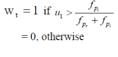 |
| Where the competitor Pr selected at random from among the 2Np trial solutions based on r = [2Np u2+ 1]. [X] denotes the greatest integer less than or equal to x, and u 1, u2 are uniform random number ranging over [0, 1]. After competing, the 2Np trial solutions, including the parents and the offspring, are ranked in descending order of the score obtained in (13). The first Np trial solutions survive and are transcribed along with their objective functions fpi into the survivor set as the basis of the next generation. A maximum number of generations (i.e., iterations) Nm, is given. |
iv). Next generation
|
| Steps (ii) and (iii) are repeated until the maximum generation or iteration count is reached Nm. The best solution at the end of the process gives the optimal solution. |
v). Calculation of optimum fitness value
|
| After reaching the minimum fitness value the cost of reactive power compensation, total active power loss and maximum voltage deviation can be calculated. |
MULTI-OBJECTIVE REACTIVE POWER COMPENSATION USING PARTICLE SWARM OPTIMIZATION
|
A. PARTICLE SWARM OPTIMIZATION
|
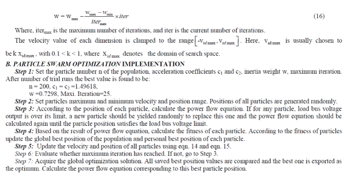
| PSO is an evolutionary computation technique developed by Kennedy and Eberhart. It is an exciting new methodology in evolutionary computation that is similar to Genetic Algorithm (GA) and EP in that the system is initialized with a population of random solutions. In addition, it searches for the optimum by updating generations, and population evolution is based on the previous generations. In PSO, the potential solutions, called particles, are "flown" through the problem space by following the current optimal particles. Each particle adjusts its flying according to its own flying experience and its companion‘s flying experience. |
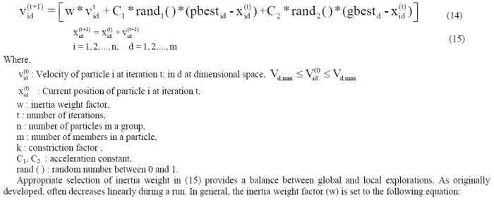
| The update of the particles is accomplished by the following (14) which calculates a new velocity for each particle (potential solution) based on its previous velocity ( id v ), the particle's location at which the best fitness so far has been achieved (pbestid), and the population global location (gbestd) at which the best fitness so far has been achieved. Equation (15) updates each particle‘s position in the solution hyperspace. The modified velocity and position of each particle can be calculated using the current velocity and distance from pbestid to gbestd as shown in the following equations: |
 |
 |
SIMULATION RESULTS
|
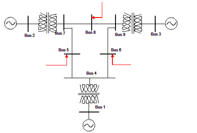
| The single line diagram of 9 bus system is shown in figure 2. |
A. EP RESULT
|
| Power system operating has to satisfy two constraints, i.e., load bus voltage limit and injected reactive power limit (Vmin = 0.95, Vmax =1.05, Qinj min = 0 Qinj max = 200). In RPC problem, different constraints considered makeup of the different calculation mathematical model. RPC is calculated for 9 bus system using EP Technique and the results are shown in Table I and Table II. |
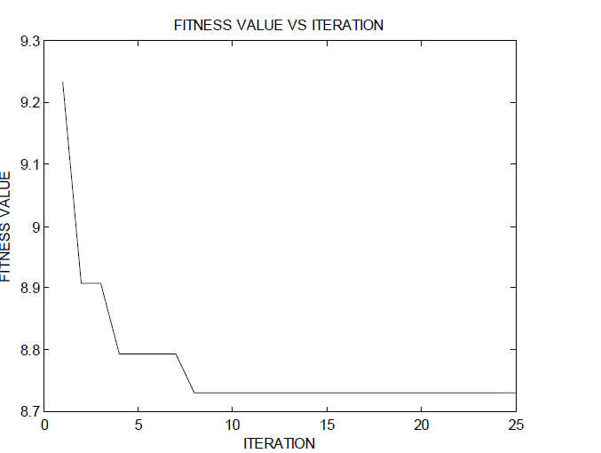
| For EP Technique, the variation of minimum fitness values with the number of iterations for population size of n = 200 is shown in figure 3. |
B. PSO RESULT
|
| RPC is calculated for 9 bus system using PSO Technique and the results are shown in Table III and Table IV. |
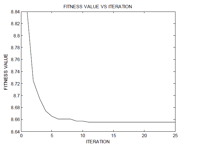
| For PSO Technique, the variation of minimum fitness values with the number of iterations for population size of n = 200 is shown in figure 4. |
C. COMPARISON RESULT
|
| The results are compared in Table V. |
| When the solutions obtained by the two optimization techniques are compared it can be clearly seen that the PSO algorithm reaches a solution very much closer to the best feasible solution as compared to EP algorithm. In case of PSO it can be observed that the losses are brought down to the minimum level. Thus, PSO technique has been successfully applied for solving the Reactive Power Compensation problem using Multi Objective function approach. |
CONCLUSION
|
| In this paper, Reactive Compensation Problem is treated as a Multi-objective Optimization Problem with 3 conflicting objective functions: (i) investment in reactive compensation devices, (ii) active power losses and (iii) maximum voltage deviation. For the 9 bus system considered the test results suggests that the line losses has reduced effectively, the voltage deviation is found to be almost zero for the corresponding injected MVAr, this concludes that by injecting reactive power, the line losses are minimized and the bus voltages are controlled. When the two optimization techniques are compared, PSO technique yields better results as compared to EP. |
Tables at a glance
|
 |
 |
 |
 |
| Table 1 |
Table 2 |
Table 3 |
Table 4 |
|
| |
Figures at a glance
|
 |
 |
 |
 |
| Figure 1 |
Figure 2 |
Figure 3 |
Figure 4 |
|
| |
References
|
- Dommel. H and Tinney. W, ?Optimal Power Flow Solutions?, IEEE Transaction Power Apparatus and Systems, Vol. PAS-87, pp. 1866-1876,Oct. 1968.
- Kundur. P, ?Power System Stability and Control?, New York: McGraw- Hill, 1993.
- Fogel. D.B, ?An Introduction to Simulated Evolutionary Optimization?, IEEE Transaction on Neural Networks, Vol. 5, pp. 3-14, Jan. 1994.
- Lee. K.Y, Bai. X and Park. Y.M, ?Optimization Method for Reactive Power Planning by using a Modified Simple Genetic Algorithm?, IEEE Transaction on Power Systems, Vol. 10, pp. 1843-1850, Nov. 1995.
- Kennedy. J and Eberhart. R, ?Particle Swarm Optimization,? IEEE International Conference on Neural Networks, Vol. 5, pp. 1942–1948, 1995.
- Lai. L.L and Ma. J.T, ?Application of Evolutionary Programming to Reactive Power Planning Comparison with Nonlinear Programming Approach?,IEEE/PES Winter Meeting, #96 WM 248-5 PWRS, Jan. 1996.
- Back. T, ?Evolutionary Algorithm in Theory and Practice?, New York: Oxford Univ. Press, 1996.
- Carlisle. J, El-Keib. A, Boyd. D and Nolan. K, ?A Review of Capacitor Placement Techniques on Distribution Feeders?, IEEE 29th Southeastern Symposium on System Theory (SSST-97), 1997.
- Foud. A.A and Anderson P.M, ?Power system Control and Stability?, The Lowa State, State University Press, 1997.
- Miu. K, Chiang. H and Darling. G, ?Capacitor Placement, Replacement and Control in Large-Scale Distribution Systems by A-Based Two-Stage Algorithm?, IEEE Transaction Power Systems, Vol. 12, pp. 1160-1166, Aug. 1997.
- Miranda. V, Srinivasan. D and Proenca. L.M, ?Evolutionary Computation in Power Systems,? Electrical Power Energy System, vol. 20, pp. 89–98,1998.
- Shi. Y and Eberhart. R, ?A Modified Particle Swarm Optimizer,? IEEE International Conference on Evolutionary Computation, Anchorage, pp. 69–73,May 1998.
- Delfanti. M, Granelli. G, Marannino. P and Montagna. M, ?Optimal Capacitor Placement using Deterministic and Genetic Algorithms?, IEEE Trans.Power Systems, Vol. 15, pp. 1041-1046, Aug. 2000.
- Eberhart. R and Shi. Y, ?Comparing Inertia Weights and Constriction Factors in Particle Swarm Optimization,? The Congress on EvolutionaryComputation, pp. 84-88, July 2000.
- Eberhart. R.C and Shi. Y, ?Particle Swarm Optimization: Developments, Applications and Resources Process Congress on Evolutionary Computation?,IEEE Service Center, Piscataway, NJ. Seoul. Korea, 2001.
- Hirotaka Yoshida, Kenichi Kawata and Yoshikazu Fukuyama, ?A Particle Swarm Optimization for Reactive Power and Voltage Control ConsideringVoltage Security Assessment?, IEEE Transaction on Power Systems, Vol. 15, pp. 1232-1239, 2001.
- Benjamin Baran, Jose Vallejos, Rodrigo Ramos and Ubaldo Fernandez, ?Multi-Objective Reactive Power Compensation?, IEEE Transaction on Power Systems, Vol. 9, pp. 97-101, 2001.
- HadiSaadat, ?Power Systems Analysis?, Tata McGraw Hill Publishing Co. Ltd. New Delhi, 2002.
- Abido. M.A and Bakhashwain. J. M, ?A Novel Multi-Objective Evolutionary Algorithm for Optimal Reactive Power Dispatch Problem?, IEEE Transaction on Power Systems, pp. 1054-1057, 2003.
|