ISSN ONLINE(2319-8753)PRINT(2347-6710)
ISSN ONLINE(2319-8753)PRINT(2347-6710)
Nilesh T. Dhokane, Savita U. Shinde, Dr. S. B. Barve
|
| Related article at Pubmed, Scholar Google |
Visit for more related articles at International Journal of Innovative Research in Science, Engineering and Technology
The sun is an outstanding energy source for mankind. It is clean and comes to the earth for free. There is no need to drill and refine it or mine it out of the ground. The devices needed to gather its energy are simple, quiet and non-polluting. International environment protection initiatives have led to the intensification of research efforts on development of ozone and global warming safe refrigeration technology. In recent years, increasing attention is being given to the use of waste heat and solar energy in energizing refrigerating systems. Solar powered refrigeration and air conditioning have been very attractive during the last twenty years, since the availability of sunshine and the need for refrigeration both reach maximum levels in the same season. The adsorption refrigeration is based on the evaporation and condensation of a refrigerant combined with adsorption. The paper describes the design and fabrication of the experimental chamber, the experimental procedure and its feasibility towards development of an alternative eco friendly refrigeration cycle for replacement of chlorofluorocarbons. The objective of this paper is to establish an alternative eco-friendly refrigeration cycle for producing a temperature usually encountered in a conventional refrigerator. By manufacturing such type of refrigerator adds new dimension to the world of refrigeration. This refrigerator gives some amount of relief to the refrigeration world by making it independent of electric power supply and zero running cost
Keywords |
| adsorption, refrigeration cycle, refrigerator, solar energy |
INTRODUCTION |
| The major attraction of solid adsorption refrigeration technology for cold production is that it can be powered entirely or partly by low grade energy such as solar energy, bio-energy etc. Its working fluids satisfy the Montreal protocol on ozone layer depletion and the Kyoto protocol on global warming. Furthermore, solar powered refrigeration based on adsorption cycle is simple, quiet in operation and adaptable to small, medium or large systems. Adsorption systems are invented with different focus. For one bed machine, simple structure and low cost are pursued. Several multi-bed systems are suggested to provide steady refrigeration and higher energy performance. One bed adsorption refrigerator is advantageous in simple structure and low initial cost. It can be used in applications when continuous cooling or higher cooling capacity is not required. Adsorption refrigeration system uses solid adsorbent beds to adsorb and desorb a refrigerant to obtain cooling effect. These solid adsorbent beds adsorb and desorb a refrigerant vapor in response to changes in the temperature of the adsorbent. Here adsorbent is an Activated carbon and the refrigerant used is methanol. The basic adsorption refrigeration system, commonly referred to as the adsorption heat pump loop, or an adsorption refrigeration circuit, it consists of four main components: a solid adsorbent bed, a condenser, and an evaporator ice-box. The solid adsorbent bed desorbs refrigerant when heated and adsorb refrigerant vapor when cooled. In this manner, the bed can be used as a thermal compressor to drive the refrigerant around the system to heat or cool a heat transfer fluid or to provide space heating or cooling. Thus in this system bed (of activated carbon) acts as compressor so as to drive refrigerant (methanol) similar to compressor in basic refrigerator. The refrigerant is desorbed from the bed as it is heated to drive the refrigerant out of the bed and the refrigerant vapor is conveyed to a condenser. In the condenser, the refrigerant vapor is cooled and condensed to liquid. The low pressure condensate passes to an evaporator where the low pressure condensate is heat exchanged with the process stream or space to be conditioned to vaporize the condensate. When further heating no longer produces desorbed refrigerant from the adsorbent bed, the bed is isolated and allowed to return to the adsorption conditions. When the adsorption conditions are established in the bed, the refrigerant vapor from the evaporator is reintroduced to the bed to complete the cycle. For the circulation of methanol in the system the whole system should be vaccumised. |
| Figure 1 shows schematic layout of a adsorption refrigeration system running on solar enegry. The solar refrigerator consists of an adsorbent bed (2), a condenser (5), an evaporator (7), water tank (8), insulation box (9) as well as connecting pipes. For this system, there are no any reservoirs, connecting valves and throttling valve, the structure of the system is very simple. The working principle of this no valve solar refrigerator is described as follows. |
| On a sunny day, the adsorbent bed absorbs solar radiation energy, which raises the temperature of adsorbent bed as well as the pressure of methanol in adsorbent bed. When the temperature of adsorbent reaches the desorption temperature, the refrigerant begins to evaporate and desorb from the bed. The desorbed refrigerant vapor will be condensed into liquid via the condenser and flows into the evaporator directly; this desorption process lasts until the temperature of adsorbent reaches the maximum desorption temperature. During night, when the temperature of the adsorbent bed reduces, the refrigerant vapor from the evaporator gets adsorbent back in the bed. During this adsorption process, the cooling effect is released from refrigerant evaporation, and the ice is formed in the water tank placed inside thermal insulated water box. |
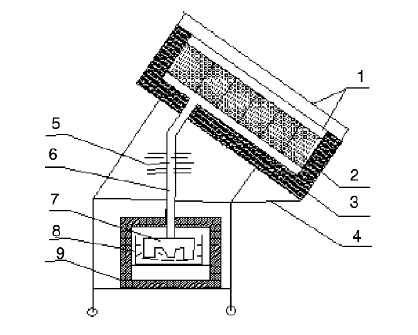 |
Figure 1: The sketch structure of the no valve solar ice maker: (1) cover plate, (2) adsorbent bed, (3) insulation materials,(4) frame, (5) condenser, (6) connecting pipe, (7) evaporator, (8) water tank, (9) insulation box. |
| Likely in a vapour compression system the adsorption refrigeration system also consists of a compressor, a condenser, and an evaporator but no throttle valve is used. However, in this system the compressor is replaced by a thermal compressor which is operated by heat instead of a mechanical energy. The vaporized refrigerant is adsorbed in the pores of the adsorbent in the reaction chamber i.e. adsorbent bed. Thus the operation of the adsorption cooling system depends on adsorption/desorption characteristics of the particular adsorbent/refrigerant pair. Due to the loading of the adsorbent, the thermal compressor is operated intermittently. |
II. DESIGN OF SOLAR POWERED SOLID ADSORPTION SYSTEM |
| The system of solar powered adsorption icemaker is composed of bed which acts as thermal collector, a condenser, evaporator and an ice box. Design of each parameter is explained in detail below. |
II.1 DESIGN OF ADSORBENT BED |
| Adsorbent bed is the most important part of the solar refrigerator and hence the performance of the solar refrigerator depends highly on the characteristics of the adsorbent bed. Generally speaking, a good adsorbent bed must have good heat and mass transfer. Recent research showed that the aluminum alloy have a stronger catalytic effect on the decomposition reaction under the solar adsorption refrigeration, therefore stainless steel is used as adsorbent heat transfer metal instead of aluminum alloy although stainless steel has poor heat transfer ability than that of aluminum alloy. The adsorbent bed is made of flat plate stainless steel box, having surface area 1 m2, also 19 kg adsorbent (activated carbon produced from coconut shell) is charged and sealed inside the steel plate box, then selective coating is covered on top surface of the steel plate box. Finally the steel plate box is placed behind sheet of fibre plastic plates in a thermal insulated case. The permeability of the fibre plastic plate for solar radiation is about 0.92, which is higher than that of glass. In order to guarantee better heat transfer between the front side and the adsorbent, many fins (also made of stainless steel) are placed inside the adsorbent bed box in contact with the front side and the activated carbon. The distance between these fins is approximately 0.15 m. The thickness of the adsorbent layer is about 0.04 m, the total weight of stainless steel metal is about 20 kg, and those parameters mentioned above are obtained according to both previous experimental results and optimized calculation. |
| In order to improve the transfer of methanol vapor through the activated carbon layer, a false bottom (0.01 m thick in the radial distance) is included in the rear side of the adsorbent bed as mentioned by Pons and Guillemiont. [1] As this ‘‘false bottom’’ is completely open to the circulation of vapors, it permits a uniform distribution of methanol in the adsorbent. |
| For the flow of methanol from the bed a hole is made at lower side of bed and coupling is made so as to connect copper tube of condenser to the bed. The schematic diagram of the adsorbent bed is shown in fig. 2 and role of adsorbent bed is as follows: As solar radiations are incident on the fibre glass which is situated above bed, activated carbon will try to absorb heat as much as it can and it gets heated thus temperature in the bed rises up to 90 °C to 100 °C. The designing starts with the making of stainless steel box of dimensions 1000mm*1000mm*70mm. this can be achieved by bending of stainless steel sheet of dimension 1090mm*1090mm.and thickness of sheet is 1mm. then it is bent at 90º, leaving 90mm of sheet from all sides, for this cuts are made so as to form a box as shown in fig. 3. |
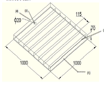 |
Figure 2: (1) adsorbent bed, (2) supporting plate and fins, (3) hole for flow of methanol vapour, (4) extension for temperature measurement |
| Here cover of box is not made it is kept open. 20 mm from upper side of box is bent again in outer side which can be used as flange to support fibre plastic glass. Then the net of stainless steel is kept at the false bottom (which is at 10 mm from bottom) as explained earlier ,on which the fins are welded to increase heat transfer rates. |
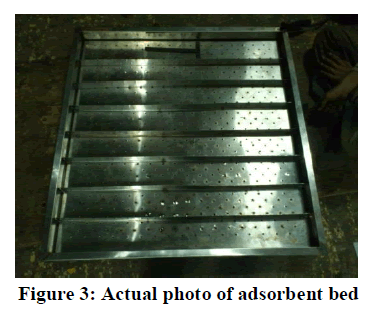
| Actual photo of adsorbent bed without fibre plastic glass and insulation is as shown in fig. 3. |
| During night activated carbon loses heat to atmosphere (exothermic reaction) thus affinity between activated carbon and methanol is gained back thus activated carbon from bed will adsorb methanol at night. Thus adsorbent bed is heart of system and it works similar to compressor in basic refrigerator so as to circulate methanol in system. |
 |
 |
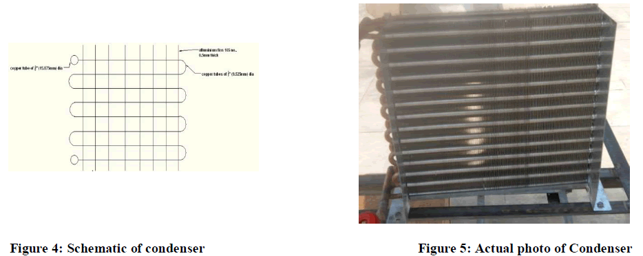 |
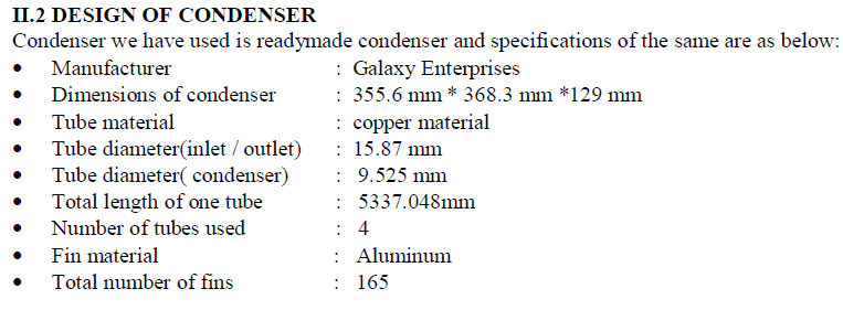
| During the process of desorption of methanol, a well designed condenser is needed to reject the desorption heat. This condenser is of air cooled type of condenser Role of condenser in the system is as follows: when vaporized methanol flows from bed to condenser through copper tube it gets cooled because of air applied on fins of condenser, thus vaporized methanol is converted into liquid methanol. This liquefied methanol now goes to evaporator. Fig. 4 & 5 show schematic and actual picture of condenser. |
II.3 DESIGN OF EVAPORATOR |
| The evaporator must have sufficient volume to collect the entire condensed methanol. In order to enhance the heat transfer effect, the heat exchange surface is designed as a series of four trapezoidal cells shown in Fig. 6 & 7, the dimension of the evaporator is 300 mm * 300 mm * 100 mm. Evaporator is made up of stainless steel The evaporator is partly immersed in a water tank, which is made of stainless steel, and both the evaporator and water tank are placed in box covered with insulation. Role of evaporator is as follows: liquefied cooled methanol from condenser goes to evaporator and here it gives refrigerating effect to the water in the container as the evaporator is partially dipped in water container. In this way, it is very simple to remove the ice formed during adsorption cooling in the night. |
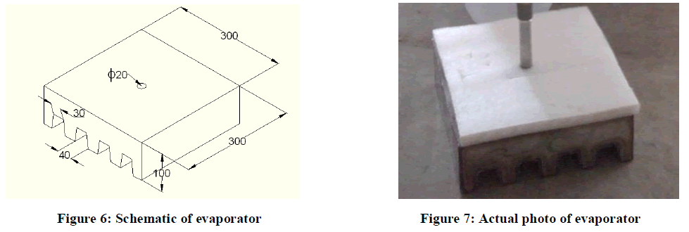 |
| The lower portion of evaporator is made up of trapezoidal shape and dimensions are 0.03m * 0.04m. This increases surface area and ensures better heat transfer. This trapezoidal portion of evaporator is made by means of sheet bending machine. Now the hollow evaporator is made by welding the stainless steel to form evaporator. Welding uses here is argon welding. Hole is made on upper side of evaporator so as to connect pipe to allow flow of methanol. |
II.4 DESIGN OF ICE-BOX |
| The diagram shown is the ice-box along with water container and an evaporator. Where, 1- Stainless steel tube of evaporator 2- Ice-box of wood 3- Water in container 4- Evaporator 5- Water container. Ice box of system is made so as to insulate the water container. It is made up of wood. Dimension of ice-box made is 406mm*355mm*508m, it is situated in lower-most portion. It is provided with door on one side so as to open the box and remove the container from the box when ice is formed. It is provided with hole on upper side of box from where copper tube of evaporator passes. Actual ice box of icemaker is as shown in fig. 8 & 9 below. |
 |
III. INTEGRATION OF SYSTEM COMPONENTS |
| The above components of the Solid Adsorption Solar Powered Refrigerator are then integrated so as to make a system work. For the integration Angles, 4 Wheels, various Nuts and Bolts, Hitlon, Teflon, Favicol, Rubber of tire, Thermocol, Cello tape, Rubber pads are used for various purposes as fixing, insulation, sticking etc. |
| Steps while integrating the system components: |
| Adsorbent bed is filled with activated carbon (which is heated first in furnace) and making sure that the granules of carbon does not pass through sieve of stainless steel net and then covered by acrylic sheet by means of bolting it to the bed. |
| Adsorbent bed is then insulated with Teflon, and cello tape. Distance between bed and acrylic sheet is then blocked by means of sealant and rubber of tyre so as to make the bed leak proof. Because of the sealing and insulation of adsorbent bed it is impossible for vaporized methanol to leak to atmosphere. |
| After the skeleton is made, adsorbent bed is then kept on it. |
| Now condenser is kept on middle angles and tube of condenser is then connected to the coupling of bed as explained in Design of Bed. To ensure proper fixing of copper tube of condenser to the coupling, Teflon is used. Condenser is then fixed to angles by means of nuts and bolts by drilling holes on angles at specific location. |
| For the flow of liquid methanol from condenser to the evaporator extra copper pipe is used which is of same diameter as that of condenser. This pipe is then bent by bending machine at specific locations so as to ensure the connection of this pipe with the evaporator tube. (Proper care is taken while bending so that the tube will not get pinched.) This tube is insulated with hetlon so that the cooled methanol should not gain heat from surrounding. |
| For the flow of liquid methanol from condenser to the evaporator extra copper pipe is used which is of same diameter as that of condenser. This pipe is then bent by bending machine at specific locations so as to ensure the connection of this pipe with the evaporator tube. (Proper care is taken while bending so that the tube will not get pinched.) This tube is insulated with hetlon so that the cooled methanol should not gain heat from surrounding. |
| Ice-box made up of wood is then kept on lower angles. And evaporator is then inserted in the box now the closing (cello tape) is removed and the pipe of evaporator is then fixed to the bent copper tube and it is sealed by means of hetlon. Water container is inserted. And rubber pads are pasted onto the container on which evaporator rests (the pads are so pasted that the evaporator is partly immersed into water) so that the weight of the system is transferred to the floor through ice-box. |
| The system is then vaccumised and pressure is then measured by means of vaccum gauge which is situated on one side of condenser The system is then kept where solar energy is available completely. |
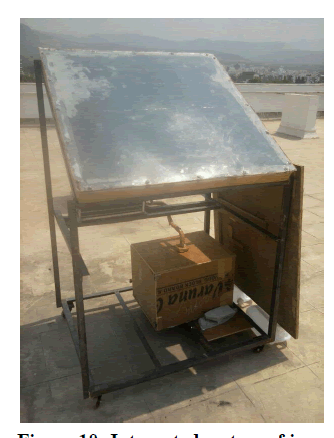 |
Figure 10: Integrated system of ice-maker |
IV. CONCLUSION |
| It is possible to consider that adsorption systems can be alternative to reduce the CO2 emissions and electricity demand when they driven by waste heat or solar energy. Although, for a broader utilization the researches should continue aiming for improvements in heat transfer, reductions of manufacturing costs and for the formulation of new adsorbent compounds with enhanced adsorption capacity and improved heat and mass transfer properties. |
| There are no valves used in this system thus the cost of the system is reduced. The condenser and evaporator must necessarily be close to each other and to the collector since the system operates at low pressure, thus they are located directly under the collector such that the refrigerant flows into them by gravity. The adsorption bed (generator) is the heart of the system and it has the greatest effect on the performance of the system. A good design of the generator leads to smooth operation and better results, so more attention must be go to the design influence on the performance of the system. The absence of noisy components is also very important features that make this type of system suitable for numerous applications. |
References |
|