Keywords
|
| MRC, Maximal likelihood receiver, AWGN |
INTRODUCTION
|
| Number of users increase in the any wireless systems needs number of Antennas are increase. Because every user had a antenna within the dynamic device. Using that antenna we receive or transmit signals. In market Lot of operators are there. Each operator had his own antennas. There is a chance to occur crosstalk between same channel or different channels. Means one operator signal is overlapped with another operator signal that we call as interference. To minimize that interference problems lot of solutions were invented. Depend on the author different techniques are used. Example of that one is in previous MIMO solves using Space Time Block Codes. |
| In this paper we solutes that problem with Maximal Ratio Combining (MRC) and Maximum likelihood receiver technique. In last versions this technique is used at N receive antennas and one transmit antenna. Now we take two antennas for transmitting and two antennas for receiving the signals. In this paper we took data as group of bits. That group contains the data of 1 and -1.That group of data transmitting through channel. Generally within the free space some noise is added. That noise is taken here as additive white Gaussian noise (AWGN).Using Maximal Raito Combine (MRC) we combine the group data and noise. At the receiver using of Maximum likelihood Receiver we received the data without any interference. That result will show in simulation result chapter. In next chapters first we designing the MRC for N receive antennas and one transmit antenna. Later we extend the technique for MIMO which is two transmitters and two receivers. |
DESIGNING APPROACH
|
A. Maximal Ratio Combine (MRC)
|
The channel is flat fading – In simple terms, it means that the multipath channel has only one tap. So, the convolution operation reduces to a simple multiplication. The channel experienced by each receive antenna is randomly varying in time. For the  receive antenna, each transmitted symbol gets multiplied by a randomly varying complex number receive antenna, each transmitted symbol gets multiplied by a randomly varying complex number  As the channel under consideration is a Rayleigh channel, the real and imaginary parts of As the channel under consideration is a Rayleigh channel, the real and imaginary parts of  are Gaussian distributed having mean are Gaussian distributed having mean  and variance and variance  The channel experience by each receive antenna is independent from the channel experienced by other receive antennas. On each receive antenna, the noise n has the Gaussian probability density function with The channel experience by each receive antenna is independent from the channel experienced by other receive antennas. On each receive antenna, the noise n has the Gaussian probability density function with  with with  |
The noise on each receive antenna is independent from the noise on the other receive antennas. At each receive antenna, the channel  is known at the receiver. . In the presence of channel is known at the receiver. . In the presence of channel  the instantaneous bit energy to noise ratio at the instantaneous bit energy to noise ratio at   |
For notational convenience, let us define  |
ASSUMPTIONS:
|
|
On the  receive antenna, the received signal is receive antenna, the received signal is  whereyi is the received symbol on the whereyi is the received symbol on the  receive antenna, receive antenna,  is the channel on the is the channel on the  receive antenna, x is the transmitted symbol and ni is the noise on receive antenna, x is the transmitted symbol and ni is the noise on 
receive antenna.Expressing it in matrix form, the received signal is,  where where  is the received symbol from all the receive antenna is the received symbol from all the receive antenna  is the channel on all the receive antenna is the transmitted symbol is the channel on all the receive antenna is the transmitted symbol  is the noise on all the receive antenna. The equalized symbol is, It is intuitive to note that the term, is the noise on all the receive antenna. The equalized symbol is, It is intuitive to note that the term,
|
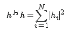 |
| i.e. sum of the channel powers across all the receive antennas. |
| Effective Eb /No with Maximal Ratio Combining (MRC): |
| To simulate for the internal noise is added. That is assumed as, we noted that in the presence of channel hi, the instantaneous bit energy to noise ratio at ith receive antenna is |
 |
| Given that we are equalizing the channel with , with the receive antenna case, the effective bit energy to noise ratio is, |
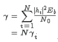 |
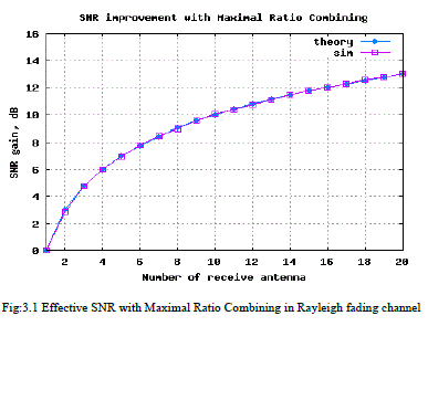
| Effective bit energy to noise ratio in a N receive antenna case is N times the bit energy to noise ratio for single antenna case shown in results Fig: 3.1. |
| B. Error Rate with CHI-SQUARE Random Variable |
| From the discussion on chi-square random variable, we know that, if hi is a Rayleigh distributed random variable, and then hi2 is a chi-squared random variable with two degrees of freedom. The pdf γiof is |
 |
| Since the effective bit energy to noise ratioγ is the sum of N such random variables, the pdf of γ is a chi-square random variable with 2N degrees of freedom. The pdf of γ is |
 |
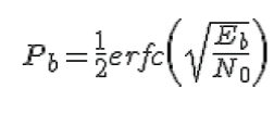
Here we added some noise which means the Bit Error Rate (BER) is occurred. In the post on BER computation in AWGN, with bit energy to noise ratio of  the bit error rate for BPSK in AWGN is derived as the bit error rate for BPSK in AWGN is derived as |
 |
| That the effective bit energy to noise ratio with maximal ratio combining isγ , the total bit error rate is the integral of the conditional BER integrated over all possible values of γ .This equation reduces to |
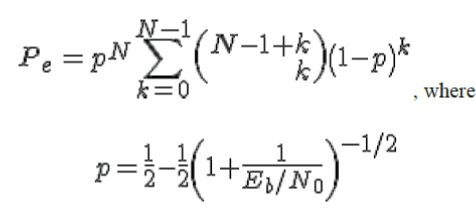 |
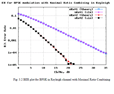
| That Resultant BER of graph is shown in Fig3.2. |
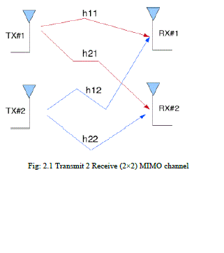
Now in this paper we solve the problem of two transmitters and two receivers which means multi input and multi output devices (MIMO). Consider that we have a transmission sequence, for example  . In normal transmission, we will be sending in the first time slot, in the second time slot, and so on. However, as we now have 2 transmit antennas, we may group the symbols into groups of two. In the first time slot, send and from the first and second antenna. In second time slot, send and from the first and second antenna, send and in the third time slot and so on. Notice that as we are grouping two symbols and sending them in one time slot, we need only time slots to complete the transmission. This forms the simple explanation of a probable MIMO transmission scheme with 2 transmit antennas and 2 receive antennas. . In normal transmission, we will be sending in the first time slot, in the second time slot, and so on. However, as we now have 2 transmit antennas, we may group the symbols into groups of two. In the first time slot, send and from the first and second antenna. In second time slot, send and from the first and second antenna, send and in the third time slot and so on. Notice that as we are grouping two symbols and sending them in one time slot, we need only time slots to complete the transmission. This forms the simple explanation of a probable MIMO transmission scheme with 2 transmit antennas and 2 receive antennas. |
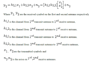
| Let us now try to understand the math for extracting the two symbols which interfered with each other. In the first time slot, the received signal on the first receive antenna is, |
 |
| The received signal on the second receive antenna is |
 |
C .Multi Input and Multi Output
|
| We assume that the receiver knows h1,1,h1,2,h2,1, and h2,2 . The receiver also knows y1 and y2. The unknown s are and . |
| For convenience, the above equation can be represented in matrix notation as follows: |
Equivalently  |
| ASSUMPTIONS: |
The channel is flat fading – In simple terms, it means that the multipath channel has only one tap. So, the convolution operation reduces to a simple multiplication. The channel experience by each transmit antenna is independent from the channel experienced by other transmit antennas. For the transmit antenna to receive antenna, each transmitted symbol gets multiplied by a randomly varying complex number . As the channel under consideration is a Rayleigh channel, the real and imaginary parts of hj,i are Gaussian distributed having mean  and variance and variance  |
| The channel experienced between each transmit to the receive antenna is independent and randomly varying in time. On the receive antenna, the noise n has the Gaussian probability density function with |
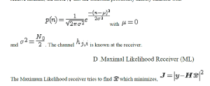 |
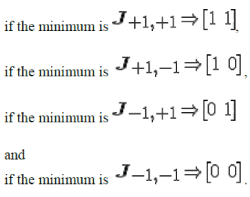
| Since the modulation is BPSK, the possible values of x1 is +1 or -1. Similarly x2 also take values +1 or -1. So, to find the Maximum Likelihood solution, we need to find the minimum from the all four combinations of x1 and x2. |
| The estimate of the transmit symbol is chosen based on the minimum value from the above four values i.e. |
 |
SIMULATION RESULTS
|
Generate random binary sequence of +1′s and -1′s. Group them into pair of two symbols and send two symbols in one time slot. Multiply the symbols with the channel and then add white Gaussian noise. Find the minimum among the four possible transmit symbol combinations. Chose that receive path, equalize the received symbols per maximal ratio combining. Perform hard decision decoding and count the bit errors. Based on the minimum chose the estimate of the transmit symbol. Repeat for multiple values of  and plot the simulation and theoretical results. and plot the simulation and theoretical results. |
| Fig: 3.1 contains Signal to noise ratio improvement which means the basic development of Maximal Ratio Combining |
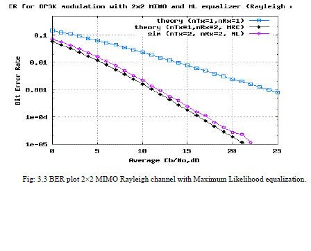
| Fig 3.2 contains at the transmitter we added Rayleigh function with BPSK modulation scheme. That Bit error rate data is transmitted. At the receiver the antenna received data is shown.Fig:3.3 contains MRC added for multi input and multi output(MIMO).At the receiver using of Maximum likelihood(ML) Receiver the data is received without any interference. |
CONCLUSION
|
| In the free space different signals are transmitting from one place to another place. Depend on the phase or frequency we receive the signals at antenna. If the antennas receive the interfered signal there is no use. To eliminate the interference we used the technique of combination of MRC and ML receiver is successfully eliminates the interference of different and internal data. |
Figures at a glance
|
 |
 |
 |
 |
| Figure 1 |
Figure 2 |
Figure 3 |
Figure 4 |
|
References
|
- Y. Wu and A. R. Calderbank, “Code diversity in multiple antenna wireless communication," in Proc. IEEE International Symp. Inf.Theory,Toronto, Canada, July 2008.
- Analysis of Transmit Antenna Selection/Maximal-Ratio Combining in Rayleigh Fading Channels Zhuo Chen ; Sch. of Electr. & Inf. Eng.,Univ. of Sydney, NSW, Australia ; Jinhong Yuan ; Vucetic, B,IEEE Vehicular technology,july2005.
- Performance analysis of maximum ratio combining with imperfect channel estimation in the presence of cochannel interferences KyungSeung Ahn ; Telecommun. R&D Center, Samsung Electron., Suwon ; Heath, R.W. Wireless Communications, IEEE Transactions on(Volume:8 , Issue: 3 ),March,2009.
- An adaptive maximum likelihood receiver for correlated Rayleigh-fading channels Communications, IEEE Transactions on (Volume:42, Issue: 9 ),Sep,1994.
- Maximum Likelihood Receiver for Multiple Channel Transmission Systems van Etten, W. ; Dept. of Electrical Engineering, EindhovenInstitute of Technology, Eindhoven, The Netherlands Communications, IEEE Transactions on (Volume:24 , Issue: 2 ),Feb,1994.
- http://www.dsplog.com/2008/07/28/chi-square-random-variable/
- http://www2.econ.iastate.edu/classes/econ500/bunzel/documents/ProbabilitySpecificSlides2.pdf
- DIG-COMM-BARRY-LEE-MESSERSCHMITT] Digital Communication: Third Edition, by John R. Barry, Edward A.Lee, David G. Messerschmitt
- Receive diversity – Notes by Prof. Raviraj Adve
- WIRELESS-TSE, VISWANATH] Fundamentals of Wireless Communication, David Tse, Pramod Viswanath
|