Research & Reviews: Journal of Material Sciences
ISSN:2321-6212
ISSN:2321-6212
1Department Materials Engineering, Ned University of Engineering and Technology, Pakistan
2Department Mechanical Engineering, Mehran University of Engineering and Technology, Pakistan
Received date: 29/06/2018; Accepted date: 13/08/2018; Published date: 20/08/2018
DOI: 10.4172/2321-6212.1000227
Visit for more related articles at Research & Reviews: Journal of Material Sciences
The study is focused on the material characterization of chassis sprocket of motor bike (Honda CD-70) and a domestic gas valve as a sample. The paper aims at basically characterizing these parts used. For this purpose, laboratory testing (Elemental, Mechanical, Metallographic and Thermal) of representative samples were done. Different heat treatment process was also used to know about any transformations that can occur with increasing temperature and what effect on hardness. To know about accurate chemical composition of the samples, XRF technique was employed. In addition, metallurgical microscope, Rockwell and Vickers hardness testing machines, and Muffle furnace were also used.
X-ray fluorescence spectroscopy (XRF), Brinell hardness number (BHN), Vicker hardness (HV).
Materials characterization techniques up to some extend match the criteria of reverse engineering in the sense that through characterization techniques; material’s structure, operation, functions, mechanical property (hardness) can be determined. Materials characterization technique is also used in failure analysis of any equipment, part of machine, or any serviceable part, to put forward the reasoning behind the failure [1].
To test this technique two samples have been chosen; one from ferrous family, and another from non-ferrous family. After characterizing the material, different heat treatment process has been done on the sample to determine the sample’s response on such treatments.
Chassis Sprocket
A chassis sprocket is part of any transportation media which helps vehicles to create forward motion, it’s a ferrous sample (which contains Fe as a major consequent), was a piece of Honda CD-motorcycles have to depend on many different
mechanical parts. It has a profiled wheel tooth like structure among all, sprocket is of great importance because most motorcycles rely on sprocket system and a simple chain to create forward motion, which is the basic function of any transportation media. Following is the picture (Figure 1).

Figure 1: Chassis Sprocket.
Gas Valve
This sample is taken to understand the difference of properties between ferrous and non-ferrous material on applying heat treatment process. Gas valve, the non-ferrous sample (which do not contain Fe as a major consequent), was a piece of domestic kitchen gas connection system [2]. It will be used to control the amount of gas flowing to create a steady flow without any gas leakage. The pictorial view of the sample is as follows (Figure 2):

Figure 2: Chassis Sprocket.
To view microscopic structure, we need to prepare sample for metallographic microscope. By analyzing a material’s microstructure, its performance and reliability can be better understood. Thus, metallography is used in materials development, incoming inspection, production and manufacturing control, and for failure analysis; in other words, product reliability [3]. For microstructural view, sample prepared by following different steps and are as:
Cutting
Dividing a big part into pieces is what we called Cutting. This is necessary step because we cannot take whole part as a sample Using Abrasive cut off machine, each sample cut into five pieces; one for as received, and remaining for heat treatment process. SiC blade is used; along with coolant which is cutting oil (01-3121) has been used along with water to maintain the fluidity. The machine worked at about 2500 rpm.
Mounting
After cutting the sample, the next step is mounting. Mounting is done to handle a small or odd shaped sample. After passing this step, a uniform sized sample is obtained. There are basically two methods:
Hot Mounting
Hot mounting is a process in which heat is applied on sample under pressure with a hot mounting press. Specimen should be clean before mounting to improve adhesion to mounting medium. Hot mounting applied on as received sample, annealed, and on normalized sample, due to the reason that the heat of hot mounting process does not affect the microscopic properties of the samples. Remaining all the samples are cold mounted, due to the reasons that even small amount of heat may affect their microstructures.
Phenolic powder was being used, and pressure of 4.6 bar was applied.
Cold Mounting
Cold mounting is usually done for samples which are sensitive to heat and get damage on applying pressure. In Cold Mounting, a mixture of resins is poured into a mold and allowed to set. In this process thermoplastics resins like epoxy resins, acrylic resins, and polyester resins, along with hardener are used. One of the reason hardener used is to make the mount solidifies on the material. The hardener is about 30 ml while the resin is taken about 100 ml. 3-4 hours needed to complete this process.
Grinding:
Grinding is required to smoothen the surface of the specimen and to minimize the damage created by sectioning. Before going into next step i.e. Polishing, specimen surface should be plane enough or a mirror like surface. The paper ranges from 180- 1200 grit/in2. Mostly Silicon Carbide paper are used in plane grinding because it is very hard. Paper ranges are as follows:
180, 220, 320, 400, 600, 800, 1000, and 1200.
Polishing
Polishing is done to remove the damage due to the sectioning and the grinding. In this step, the surface of the sample is made mirror like, free from all surface defects. In polishing step, it is divided in two steps, which are:
Rough Polishing
The purpose of rough polishing step is to remove the damage produced during cutting and planar grinding. Specimen flatness and secondary phases maintain through rough polishing. In this step the paper named as palano, and s-palano is used along with the alumina suspension. The particle size in the suspension is 1 μm and 5 μm.
Fine polishing
The purpose of fine polishing is to remove only surface damage. It should not be used to remove any damage remaining from cutting and planar grinding. α-gram paper with 0.5 μm alumina suspension (in water) is used. For very hard materials diamond paste is used as suspension.
Etching
The purpose of etching is to optically enhance microstructural features such as grain size and phase features. Etching selectively alters these microstructural features based on composition, stress, or crystal structure. The most common technique for etching is selective chemical etching and numerous formulations have been used in Table 1.
Table 1: Etchants of Samples.
| Sample | Etchant | Chemical Composition | Volume | Conditions |
|---|---|---|---|---|
| Chassis Sprocket | Nital | Ethanol+Nitric Acid | 98 ml+2 ml | Immersion up to a few minutes |
| Gas Valve | Cu+Brass | FeCl2+HCl+Ethanol | 2.5 ml+1 ml+48 ml | Immersion up to a few minutes |
Metallurgical microscope generally uses to view opaque objects at higher magnification, usually these microscopes have higher magnification compared to others [4]. To view objects like electroplating coatings, thin films, grain size, surface inclusions and defects.
Using bright field metallurgical microscope, following structures are obtained in Figures 3 and 4.
Microstructure of sample as received:

Figure 3: Microstructure of Chassis Sprocket.

Figure 4: Microstructure of Gas Valve.
Generally, this spectroscopy is used for non-destructive chemical analysis. This phenomenon is used for elemental and chemical analysis, particularly in the investigation of ceramics, glass, metals and building materials. This technique gives accurate results of what is present. The excited sample in turn emits X-rays along a spectrum of wavelengths characteristic of the types of atoms present in the sample. The atoms in the sample absorb X-ray energy by ionizing, ejecting electrons from the lower (usually K and L) energy levels [5]. The ejected electrons are replaced by electrons from an outer, higher energy orbital. When this happens, energy is released due to the decreased binding energy of the inner electron orbital compared with an outer one. This energy release is in the form of emission of characteristic X-rays indicating the type of atom present. Following is the mechanism:
Mechanism of XRF can be understand through this picture (Figure 5).

Figure 5: Mechanism of XRF.
XRF results of both samples is as follows (Tables 2 and 3).
Table 2: XRF Result of Gas Valve.
| Gas Valve | |
|---|---|
| Element | Percentage |
| Cu | 55.45% |
| Zn | 29.93% |
| Pb | 11.43% |
| Sn | 1.28% |
| Fe | 0.93% |
| Ni | 0.63% |
| Sb | 0.35% |
Table 3: XRF Result of Chassis Sprocket.
| Chassis Sprocket | |
|---|---|
| Element | Percentage |
| Mn | 0.38% |
Determination of Grades of the sample:
By above elemental analysis through XRF, grades of steel are also important to be known.
Using Atlas of Metal handbook, it is concluded in Table 4.
Table 4: Grades of the samples.
| Sample | Structure | Chemical Composition | Grade |
|---|---|---|---|
| Chassis Sprocket | 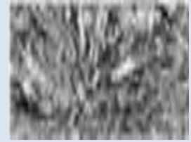 |
92.27% Fe | 10B35 (Steel) |
| 0.35%c | |||
| 0.38% Mn | |||
| Gas Value | 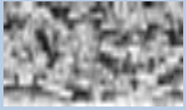 |
60%Cu | (Brass-Muntz Metal) |
| 40%Zn |
Heat treatment is a group of processes which is used to alter microstructure of metals and alloys such as steel and aluminum [6]. To alter steel microstructure, we have employed different processes and check the effect of each.
Steel samples were quenched, tempered, normalized, and annealed. The heating temperature was about 850˚C. As the maximum thickness of the sample is about 1.4˝ so, the soaking time was chosen as 45 minutes. Brass samples were quenched, normalized, annealed according to proper thickness, and annealed with long soaking time. Temperature was about 700˚C and the soaking time was 10 minutes, and was 45 minutes only for long annealed sample.
Quenching
Quenching is a process generally used to obtain high strength and toughness. In this process sample cooled rapidly from austenitizing temperature. Generally, in ferrous alloys (such as carbon steel, alloy steel and stainless steel), it transforms microstructure from austenite to martensite (harder metal), while non-ferrous alloys (brass, aluminum, and super alloys) will usually become softer than normal.
The quenching media was water for both samples. Heating and cooling curves for both samples are shown below (Figures 6 and 7).

Figure 6: Heat Treatment Cycle of Quenching of Steel (10B35).

Figure 7: Heat Treatment Cycle of Quenching of Steel (C37000).
Normalizing
Normalizing is a heat treatment process in which sample is heated to obtain uniformity in grains and in microstructure. In this process, a sample is heated above it’s critical limit and then cooling in open air. Normalizing can also be used for cast irons to produce more uniformity, improved wear resistance, and increased hardness values [7]. Below is the normalizing cycle of both the samples (Figures 8-11).

Figure 8: Heat Treatment Cycle of Normalizing of Steel (10B35).

Figure 9: Heat Treatment Cycle of Normalizing of Brass (C37000).

Figure 10: Heat Treatment Cycle of Annealing of Steel (10B35).

Figure 11: Heat Treatment Cycle of Annealing of Brass (C37000).
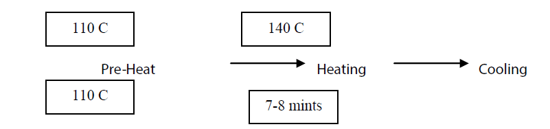
Annealing
Annealing process involves heating steel to a specified temperature and then cooling at a very slow and controlled rate. Annealing commonly used to improve machinability, shown in Figures 12-17.
Microstructure of Heat Treated Samples

Figure 12: Microstructure of Quenched Steel (10B35)

Figure 13: Microstructure of Quenched Brass (C37000).
Microstructure of Normalized Samples

Figure 14: Microstructure of Normalized Steel (10B35).

Figure 15: Microstructure of Normalized Brass (C37000).
Microstructure of Annealed Samples

Figure 16: Microstructure of Annealed Steel (10B35).

Figure 17: Microstructure of Annealed Brass (C37000).
Hardness is defining as the resistance to indentation. Hardness is not fundamental physical property, it is a characteristic of a material [8,9]. There are different hardness machines that are used to calculate the hardness of a material. We have used Rockwell Hardness Test Method to analyses hardness of the samples (Tables 4 and 5).
Hardness of the Samples before Heat Treatment
Table 5: Hardness of Sample of Brass (C37000).
| Gas Valve | ||
|---|---|---|
| Indent position | HRB | Mean HRB |
| Surface | 64 | 61.16 |
| mild | 63 | |
| core | 56.5 | |
Hardness of Heat Treated Samples
Generally, ferrous material hardness increases on heating whereas for non-ferrous material it is reversed. Below are the hardness table developed after testing samples on Rockwell machine [10].
Hardness of Quenched Samples
This can be clearly seen from the below table that after quenching process hardness of the sample increases (Tables 6-10).
Table 6: Hardness of Sample of Steel (10B35).
| Chassis Sprocket | ||
|---|---|---|
| Indent position | HRB | Mean HRB |
| Surface | 116 | 114.33 |
| mild | 115 | |
| core | 112 | |
Table 7: Hardness of Quenched Sample of Steel (10B35).
| Chassis Sprocket | ||
|---|---|---|
| Indent position | HRB | Mean HRB |
| Surface | 95 | 94.5 |
| mild | 94.5 | |
| core | 94 | |
Hardness of Normalized Samples
Table 8: Hardness of Quenched Sample of Steel (10B35).
| Gas value | ||
|---|---|---|
| Indent position | Chassis Sprocket | Mean HRB |
| Surface | 58.5 | |
| mild | 54 | 54.16 |
| core | 50 | |
Table 9: Hardness of Normalized Sample of Steel (10B35).
| Chassis Sprocket | ||
|---|---|---|
| Indent | Chassis | Mean HRB |
| position | Sprocket | |
| Surface | 80 | 79.66 |
| mild | 80 | |
| core | 79 | |
Hardness of Annealed Samples
Table 10: Hardness of Normalized Sample of Steel (C37000).
| Gas Valve | ||
|---|---|---|
| Indent position | HRB | Mean HRB |
| Surface | 70 | 67.66 |
| mild | 69 | |
| core | 64 | |
The data which was collected during the experimental work elaborates clearly the steps for reverse engineering and the effect of heat treatment on microstructure and hardness. First consider the steel sample, it was seen that has received structure of steel was martensite (Figure 3), after heat treatment it was transformed to different microstructure comparing to the initial one. Quench treatment made martensitic structure because C in steel didn’t get appropriate time to escape from the structure and got trapped in microstructure due to fast cooling rate but with a little grain growth (Figure 12). Normalize treatment made the grains to grow more compared to quench sample Figure 14 because of moderate cooling. Annealing treatment releases all the stresses from the sample and the grain growth is maximum in this treatment because of very slow cooling rate. The hardness of non-heattreated sample is maximum, after that quenched, then normalized, and minimum hardness was obtained from the annealed sample (can be seen from the curves obtained). All effect is due to the holding time and cooling rate. As the quenched sample has the fastest cooling rate, so it should give the structure more distorted which yields maximum hardness among all heat-treated samples but it was seen that tempered sample has the maximum hardness although it was the combination of quenching and normalizing. The annealed sample due to furnace cooling, cools very slowly so C in it gets a lot of time to relax them. The same reason is for all the heat-treated samples.
Now, consider brass, the results of brass samples were in contrast with respect to quenched and normalized samples of steel. As received structure of brass has coarse grains Figure 4 because it didn’t cold treat. Quenching does not affect highly on the sample and the results have very less difference both in microstructure and in hardness Figure 13 and Table 6 respectively. Normalizing treatment has strong effect; it gives maximum hardness, and more complex structure comparing to all although the cooling rate is moderate (Figure 15). Annealing treatment gives long grains with low hardness values
Figure 17 Annealing with long soaking time gives the minimum hardness and the grain growth is maximum due to extreme holding time, which gives maximum time to grow grains. Since, the grain growth is maximum so the hardness reduces very suitably as according to the phenomena.
So, this result can be taken from the whole paper that by given inadequate holding time (greater than its thickness requirement) hardness of the sample decreases very effectively. Therefore, hardness has inverse relation with grain size.
Steels are most important and fundamental material to support lives and industries at present and in the future. We attempt to control mechanical properties of metallic structural materials through microstructure control and to clarify principles of microstructure evolution by means of advanced experimental and theoretical techniques.
For future work, this paper focus on advanced control of micro/nanostructures, such as atomic structures of crystalline interfaces, chemistry in an atomic scale (e.g., segregation) and so on. fundamentals of microstructure formation (thermodynamics, kinetics, crystallography) are examined both theoretically and experimentally to clarify key factors for microstructure control to improve mechanical properties.
i) This project is not limited only with metals (ferrous and non-ferrous), but can also, be extended to ceramics, composites, and polymers also.
ii) This project is also not limited to just four heat treatment processes but also, sub-zero, treatment can be done on the samples to check their responses to such a low temperature. Also, air hardening, austempering, martempering effect can also be studied.
iii) Different hardening processes can be applied to check which one is best suitable for any specific given conditions.
iv) Also, the effect of different heat treatment processes can be concluded.
v) The effect of different quenching medium can be practically determined on any given sample.