ISSN ONLINE(2319-8753)PRINT(2347-6710)
ISSN ONLINE(2319-8753)PRINT(2347-6710)
P N H Phanindra kumar1, D M Deshpande2, Manisha Dubey2
|
| Related article at Pubmed, Scholar Google |
Visit for more related articles at International Journal of Innovative Research in Science, Engineering and Technology
This paper describes the various mathematical models of both squirrel cage and wound rotor induction motors in different reference frames with different state-space variables. The work suggests the d-q axis unified approach for both types of induction motors by using the state-space analysis and it is a strong tool in the modeling of the symmetrical induction motors. When an electrical motor is represented as a mathematical model with inputs and outputs, it can be analyzed and described in many ways, considering different reference frames and state-space variables. The applications of each model are also discussed. Models are simulated with MATLAB/SIMULINK software for transient response of the squirrel cage induction motor in terms of electromagnetic torque and rotor angular velocity and results are discussed.
Keywords |
| modeling of induction motor, sensor less control, d-q axes model, and different reference frames. |
INTRODUCTION |
| Due to advances in control system, induction motor is used as variable speed drive. When an electrical motor is represented as a mathematical model with inputs and outputs, it can be analyzed and described in many ways, considering different reference frames and state-space variables. In three-phase symmetrical or two-phase unsymmetrical version, the induction motor is employed with vector control strategy. Thus, induction motor can be analyzed as DC motor [1]. |
| The dynamic operation of the induction motor drive system has an important role in the overall performance of the system and there are two fundamental methods for the induction motor control: one is the Direct measurement of the machine parameters, which are compared to the reference signals through closed control loops and other is the estimation of the machine parameters in the sensor less control schemes, with the following implementation methodologies: slip frequency calculation method, speed estimation using state equation, estimation based on slot space harmonic voltages, flux estimation and flux vector control, direct control of torque and flux, observer-based speed sensor less control with parameter adaptation, neural network based sensor less control, fuzzy-logic based sensor less control.[2] |
| The development of the precise system model is fundamental to each stage in the design, analysis and control of all electrical machines. The level of accuracy required for these models entirelydepends on the design stage under consideration. In some cases, the mathematical description used in machine design requires very fine tolerance levels as stated by Nabae and Murata [3], [4]. However, in the development of suitable models for control purposes, considercertain assumptions that simplify the resulting machine model. Additionally, since modern electric machines are continuously fed from switching power conversion stages, the developed motor models should be valid for arbitrary applied voltage and current waveforms [5]. Generally, the following assumptions are made while implementing the induction motor models |
| • No magnetic saturation. |
| • No saliency effects. |
| • Negligible spatial MMF harmonics. |
| • The effects of the stator slots may be neglected. |
| • There is no fringing of the magnetic circuit. |
| • The magnetic field intensity is constant quantity and directed radiallyacross the air-gap. |
| • Hysteresis and eddy current effects are negligible. |
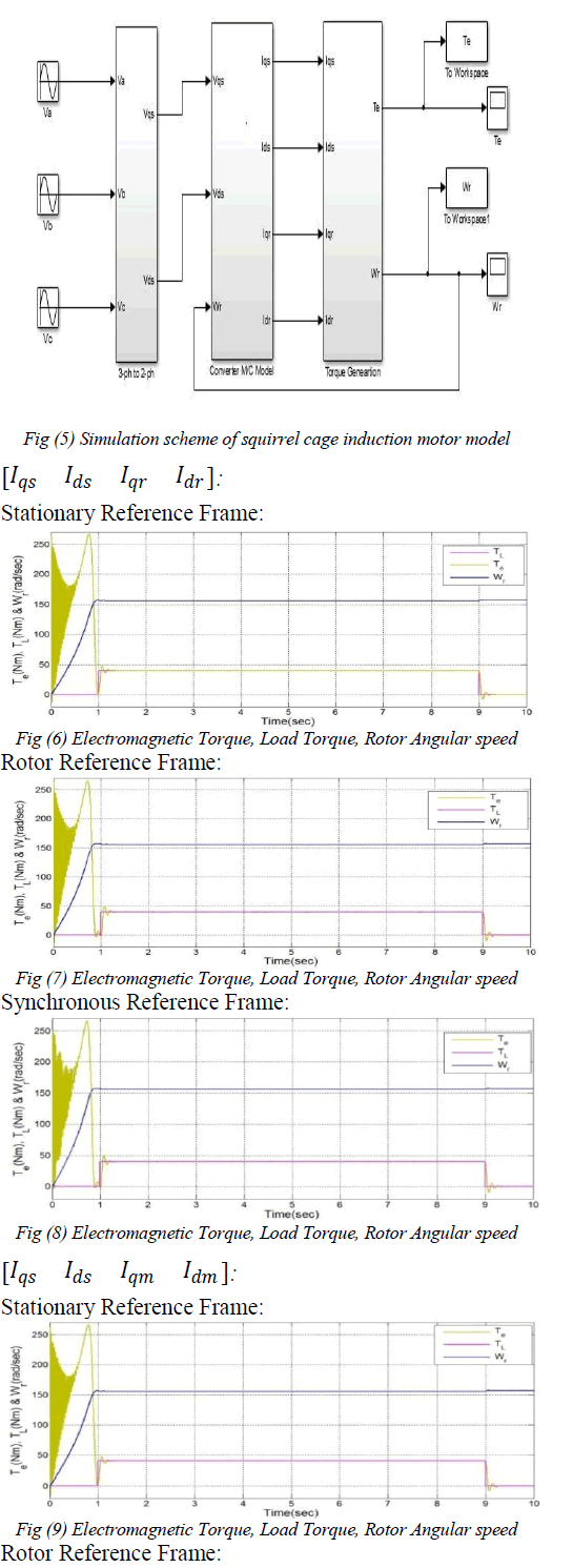
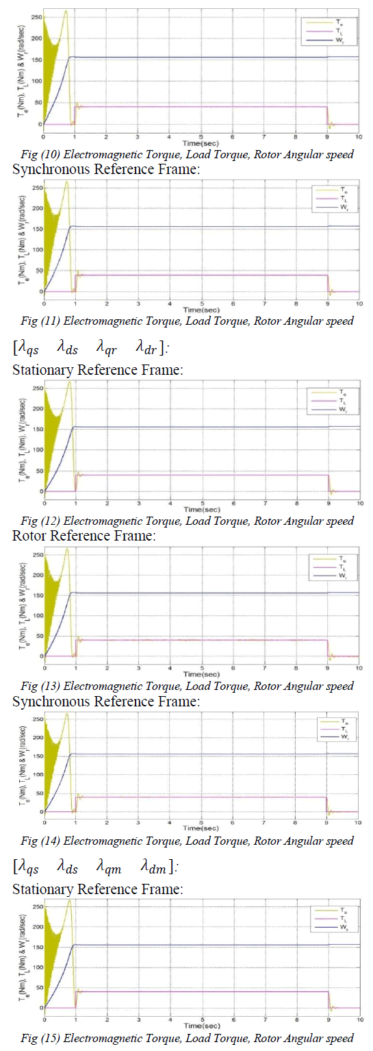
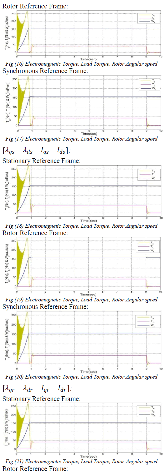
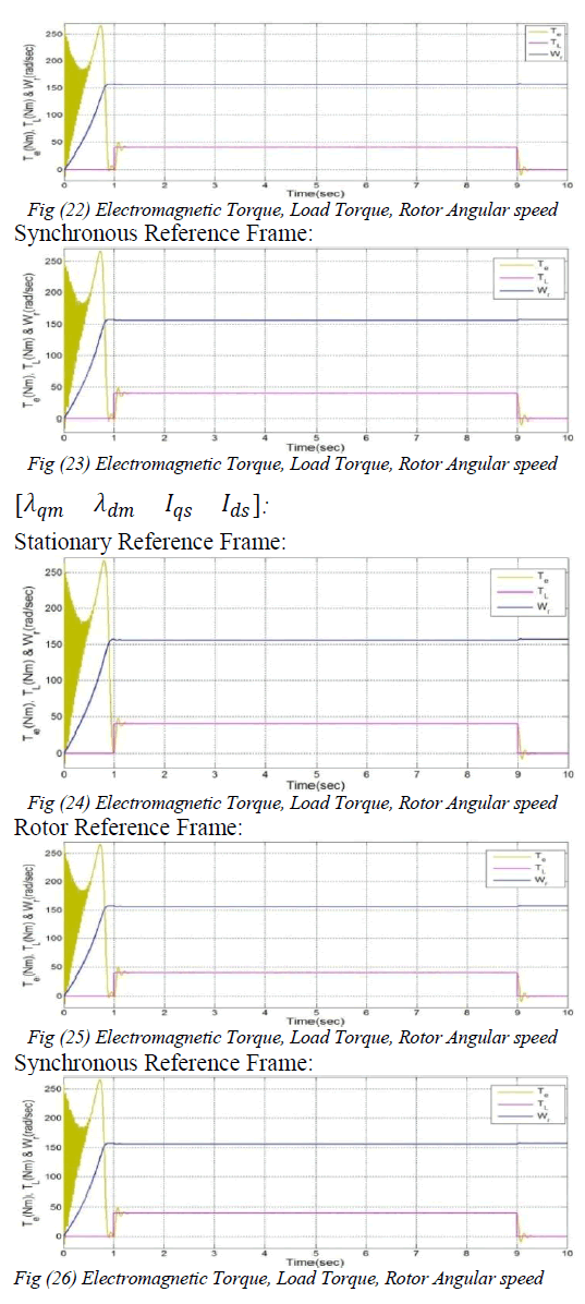
| The goal of this paper is to establish the commonly used d-q models in different reference frames. Matlab/Simulink software is used to simulate the dynamic models of squirrel cage induction motor. The paper has been organized as follows: section II briefly explains the measurement of motor parameters, section III demonstrate the mathematical model of the induction motor, section IV describes the d-q axis models, and the results of implemented Matlab models are shown in section V. |
MEASUREMENT OF ROTOR PARAMETERS |
| A. Stator Resistance |
| The stator phase resistance is measured by applying a DC voltage and the resulting current with the rotor at standstill. This procedure gives only the DC resistance at a certain temperature, the AC resistance is calculated by considering the wire size, the stator frequency and the operating temperature. |
| B. No-Load Test |
| This test is performed by applying a balanced rated voltage on the stator windings at the rated frequency and driven at synchronous speed by DC motor or synchronous motor, preferably a DC motor. The no-load test provides information about exciting current and rotationallosses. |
| C. Locked-Rotor Test |
| The rotor of the induction motor is locked and a set of low three phase voltages is applied to calculate rated stator currents. The input power per phase is measured along with the input voltage and stator current. The locked rotor test provides the information about leakage impedances and rotor resistance. [7] |
MODELING OF IN DUCTION MOTOR |
| A. Space vector equations for three-phase induction motor |
| For the modeling of three-phase induction motor generally two theories are used. First one is the two real axis reference frame theory initially developed by Park for the synchronous machine [8]. Second one is the space complex vector theory elaborated by Kovacs and Racz [9]. Both theories are used to describe the complete equations system of continuous-time linear model of the induction motor with certain assumptions. Usually, the following assumptions are made [10]: |
| • Geometrical and electrical machine configuration is symmetrical. |
| • Space harmonics of the stator and rotor magnetic flux are negligible. |
| • Infinitely permeable iron. |
| • Stator and rotor windings are sinusoidally distributed in space and replaced by an equivalent concentrated winding. |
| • Magnetic saturation, anisotropy effect, core loss and skin effect are negligible. |
| • Windings resistance and reactance do not vary with the temperature. |
| • Currents and voltages are sinusoidal terms. |
| • End and fringing effects are neglected |
 |
 |
 |
 |
 |
 |
 |
 |
 |
 |
 |
 |
CONCLUSIONS |
| In this paper, various mathematical d-q models of both squirrel cage and wound rotor induction motors in different reference frames are presented. This paper presents the d-q axes unified approach for both types of induction motors. The applications of each model are also discussed. Models either only with magnetisation current space vector or air-gap flux space vector, or both includes saturation effect in modeling of induction motor. MATLAB/SIMULINK software was used to implement the dynamic response of squirrel cage induction motor d-q models in different reference frames and these models are analyzed in terms of torque and rotor angular velocity. |
References |
|