Keywords
|
| UWB, OFDM, SINR, Diversities. |
INTRODUCTION
|
| Ultra wideband (UWB) communication is one of the most promising technologies. The very large bandwidth in the spectrum (from 3.1−10.6 GHz) allows for innovative communication systems that are able to transmit data in a very fast and an efficient manner. |
| Multipath interference is a problem in narrowband technology, which causes fading and wave interference is destructive. Some UWB systems use "rake" receiver techniques to recover multipath-generated copies of the original pulse to improve receiver performance. Other UWB systems use channel-equalization techniques to achieve better performance. [3] |
| IR-UWB can be further subcategorized in Time Hopping (TH) UWB and Direct Sequence (DS) UWB. Impulse based UWB, usually offers only one physical channel and in order to transmit maximum effect it is imperative that this channel covers the available spectrum as completely as possible. A signal that perfectly fills the available 3.1 GHz – 10.6 GHz bandwidth gives a maximum transmission power of 0.55mW (-2.6dBm) when integration over the FCC mask is performed. The spectrum of the transmitted signal will depend on the pulse shape of the signal and way in which the pulses are placed in time domain. The most common pulse shapes are different variations of Gaussian pulses. |
| There are several types of modulation schemes that can be applied within each of the respective bands. Orthogonal Frequency Division Multiplexing (OFDM) is however the most common. The Multiband OFDM Alliance (MBOA) is a worldwide organization consisting of more than 60 leading companies that support a single technical proposal for MB-UWB. For high data rate applications, UWB would be the better solution because of its low normalized energy consumption. The advantages of UWB systems include simplicity of implementation, high data rate, inherent robustness to multipath fading, flexibility of operation, low power consumption and low cost of implementation. |
RELATED WORK
|
| In OFDM, ISI usually refers to interference of an OFDM symbol by previous OFDM symbols. In addition to protecting the OFDM from ISI, the guard period also provides the protection against time-offset. The advantages of OFDM is efficiently dealt with multi-path fading, channel delay spread, enhanced channel capacity, adaptively modifies modulation density and robustness to narrowband interference.The downsides of OFDM are complexity of FFT for modulation and demodulation that must be compared to complexity of equalizer, synchronization and overhead. Cyclic Extension increases the length of the symbol for no increase in capacity. Pilot Tones simplify equalization and tracking for no increase in capacity. |
MIMO
|
| Multiple antenna techniques can be broadly classified into two categories namely diversity techniques and spatial-multiplexing techniques. The diversity techniques intend to receive the same information-bearing signals in the multiple antennas or to transmit them from multiple antennas, thereby improving the transmission reliability. A basic idea of the diversity techniques is to convert Rayleigh fading wireless channel into more stable AWGN like channel without any catastrophic signal fading. |
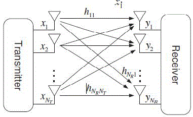
| In the spatial-multiplexing techniques, on the other hand, the multiple independent data streams are simultaneously transmitted by the multiple transmit antennas, thereby achieving a higher transmission speed. When the spatial-multiplexing techniques are used, the maximum achievable transmission speed can be the same as the capacity of the MIMO channel; however, when the diversity techniques are used, the achievable transmission speed can be much lower than the capacity of the MIMO channel. The NR×NT MIMO SYSTEM was shown in Fig.2.1 which consists of multiple transmitters and multiple receivers. |
| A typical multi-user communication environment in which the multiple mobile stations are served by a single base station in the cellular system. Three out of four users are selected and allocated communication resource such as time, frequency and spatial stream. |
MIMO-OFDM CONJUNCTION
|
| All Wireless links are affected by three common problems of speed, range and reliability. These parameters are interlinked to each other by strict rules. Speed could be increased only by sacrificing range and reliability. Range could be extended at the expense of speed and reliability could be improved by reducing speed and range. MIMOOFDM provides the 'all in one package' by providing the speed, range and reliability simultaneously. |
| With OFDM, a single channel within a spectrum band can be divided into multiple, smaller sub-signals that transmit information simultaneously without interference. Because MIMO technology is able to link together many smaller antennas to work as one, it can receive and send these OFDM multiple sub-signals in a way that allows the bandwidth to be substantially increased to each user as required. OFDM is the technique used to mitigate the multipath propagation problem and MIMO is used for the efficient usage of spectral bandwidth thus combining these techniques, results in wireless system with best spectral coverage and reliable transmission for fading environment. MIMO caters the spatial diversity whereas OFDM can use either FDD or TDD multiplex technique. In the spatial domain, MIMO provide greater capacity. The modulation method in OFDM simplifies the equalization process by eliminating the inter symbol interference (ISI). |
| With the combination of MIMO and OFDM, greater channel capacities could be achieved and realized with robustness to channel impairments like ISI through cyclic prefix (CP) and multipath fading through adaptive bit loading. OFDM generates slow time varying channel streams and MIMO has capacity of transmitting the signals over multiple channels by use of an array of antennas. Thus the combinations are greatly affected by FDM while MIMO can generate extremely beneficial results. OFDM signals by the presence of objects, while on the other hand the MIMO takes its advantage from multipath propagation. |
RAKE RECEIVER
|
| A rake receiver is a radio receiver designed to counter the effects of multipath that is, several correlators are assigned to a different multiple component. Each finger independently decodes a multipath component; at a later stage fading. It does this by using several "sub-receivers" called fingers, that the contribution of all fingers are combined in order to make the most use of the different transmission characteristics of each transmission path. This could very well result with better signal to noise ratio (or Eb/No) in a multipath environment than in a "clean" environment. |
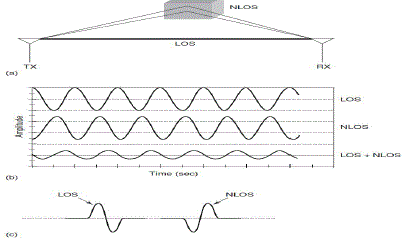
| The multipath channel through which a radio wave transmits can be viewed as transmitting the original (LOS) wave pulse through a number of components. These components are delayed copies of the original transmitted wave travelling through a different echo path, each with a different magnitude and time-of-arrival at the receiver. Since each component contains the actual information, if the magnitude and time-of arrival (phase) of each component is computed at the receiver (through a process called channel estimation), then all the components can be added coherently to improve the information reliability. Rake receivers are common in a wide variety of CDMA and WCDMA radio devices such as mobile phones and WLAN equipment. |
ENERGY DETECTION RECEIVER
|
| Energy detection receiver is a non-coherent receiver used to determine the power spectral density of signal. It collects energy from multipath (i.e.) integrates the energy of received signal. No antipodal signaling possible and no need for channel estimation in this receiver. |
EXISTING SYSTEM
|
| Energy detection receivers for UWB impulse radio communication with binary pulse position modulation (BPPM) are very vulnerable to narrowband interference. Therefore, transmitter and receiver optimization schemes based on the Signal to Interference-plus-Noise-Ratio (SINR) was derived. First, SINR optimization based on full channel knowledge is presented. The location knowledge is then incorporated by means of a statistical channel model. Performance evaluation based on a simple channel model is used to give insight about the fundamental behavior of the derived optimization schemes. Location knowledge can improve the data transmission and helps to successfully suppress narrowband interference.[1] |
BLOCK DIAGRAM OF SYSTEM MODEL
|
| The block diagram of system model is shown in Fig.2.1. The transmitter uses BPPM, i.e. |
 |
| For transmission of symbols an=0, a pulse p (t) is sent in the first time slot and for a “1”, it is sent in the second time slot. The length of the time slot Tppm is half the symbol duration Tsymb. The polarity cn of the pulses is chosen randomly to avoid discrete spectral lines in the spectrum of the transmit signal. [4] |
| The generalized energy detector consists of a band-pass filter of bandwidth B and center frequency fc, a squaring device and the post-detection filter with impulse response g (t). Data detection is based on two samples per symbol taken at the energy detector output. The energy in the first time slot is compared to the energy in the second time slot. If the post-detection filter has a rectangular impulse response (sliding window integrator) then the generalized energy detection receiver corresponds to a conventional energy detector. |
| In terms of detection performance, the post-detection filter can be adapted to the channel conditions and the narrowband interference scenario. The transmission of a single symbol a0 € {0, 1}.Thermal noise plus narrowband interference are modelled as zero-mean Gaussian random vectors n (first time slot) and n’ (second time slot). Their covariance matrix including the band-pass filter are given by |
 |
 |
| Σw and Σi denotes the covariance matrix of the band-limited noise and interference respectively. The impulse response of the post detection filter is stacked into a vector in reverse order, i.e. g= (g [N], g [N-1]… g [1]) T. This system model is equivalent to the continuous time transceiver structure depicted in Fig.3.1 under the following assumptions: |
i. The sampling Period TS must fulfill at least  to account for the squaring operation. to account for the squaring operation. |
| ii. Narrowband interference is Gaussian distributed. |
| iii. The transmit bits are equally probable and only one pulse is transmitted per symbol with perfect synchronization at the receiver. |
SIGNAL TO INTERFERENCE AND NOISE RATIO
|
| The signal-to-interference-and-noise ratio (SINR) is defined as |
 |
| where z0 denotes the receiver output and expectation is with respect to noise and interference. The term α collects the desired signal contribution, i.e. the received pulse q, which is squared and convolved with the post detection filter. All perturbing contributions are combined other terms: in β the product of the signal and noise plus interference and in γ the squared noise plus interference contribution of the first and second timeslot respectively. The SINR can be written in terms of the squared signal, the mixed term and the squared noise term as follows: |
 |
| For channel realization, the following prepositions are used. |
| Preposition 1: SINR in terms of the transmit pulse ‘p’. |
| Preposition 2: SINR in terms of the post-detection filter ‘g’. |
| The optimization of transmitter or receiver schemes based on statistical channel knowledge i.e. the covariance matrix of the channel impulse response to incorporate location knowledge.[5] |
DISADVANTAGE OF EXISTING SYSTEM
|
| The receiver is vulnerable to narrowband interference and BER is higher than 0.1. More complexity involves in achieving BER and SINR with transmitter and receiver optimization scheme. |
PROPOSED SYSTEM
|
USE OF IMPULSE PULSE
|
| Ultra wideband communications is fundamentally different from all other communication techniques because it employs extremely narrow RF pulses to communicate between transmitters and receivers. A continuous waveform has well-defined signal energy in a narrow frequency band that makes it very immune to detection and interception. Fig.4.1 represents a UWB pulse in time and frequency domains. |
| Low duty cycle offers a very low average transmission power in UWB systems. The average transmission power of a UWB system is on the order of microwatts, which is a thousand times less than the transmission power of a cell phone. However, the peak or instantaneous power of individual UWB pulses can be relatively larger too but because they are transmitted for only a very short time (Ton less than 1 ns), the average power becomes considerably lower. Consequently, UWB devices require low transmit power due to this control over the duty cycle which directly translates to longer battery life for handheld equipment. Since frequency is inversely related to time the short-duration UWB pulses spread their energy across a wide range of frequencies from near DC to several gigahertz (GHz) with very low power spectral density (PSD). |
| The wide instantaneous bandwidth results from the time-scaling property of theoretical Fourier transforms: |
 |
| The notation on the left side of equation shows a signal, x(t), which is scaled in the time domain by a factor a; the right side represents the same signal in the frequency domain, X(f), which is inversely scaled by the same factor a. |
| A UWB signal can be any one of a variety of wideband signals such as Gaussian, chirp, wavelet or Hermitebased short-duration pulses. The following equation represents a Gaussian monocycle as an example of a UWB pulse in the time and frequency domains. The Gaussian monocycle is the first derivative of a Gaussian pulse and is given by |
 |
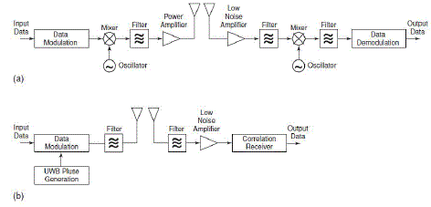
| UWB transmission is carrier less, meaning that data is not modulated on a continuous waveform with a specific carrier frequency, as in narrowband and wideband technologies. Carrier less transmission requires fewer RF components than carrier based transmission. For this reason UWB transceiver architecture is significantly simpler and thus cheaper to build. Fig.4.3 compares the block diagrams of typical narrowband and UWB transceivers. The UWB transceiver architecture is considerably less complicated than that of the narrowband transceiver. The transmission of low-powered pulses eliminates the need for a power amplifier (PA) in UWB transmitters. [7] |
| Also, because UWB transmission is carrier less, there is no need for mixers and local oscillators to translate the carrier frequency to the required frequency band; consequently there is no need for a carrier recovery stage at the receiver end. In general, the analog front end of a UWB transceiver is noticeably less complicated than that of a narrowband transceiver. This simplicity makes an all-CMOS (short for complementary metal-oxide semiconductors) implementation of UWB transceivers possible, which translates to smaller form factors and lower production costs. |
RESULTS AND DISCUSSION
|
ANALYSIS OF RAKE RECEIVER
|
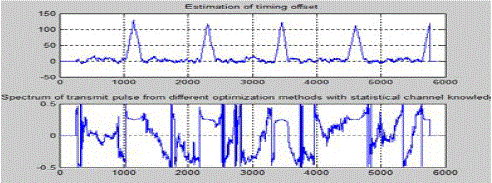
| To initialize the following parameters to UWB environment as FFT samples=1024, CP=128, Symbol=6, Frequency offset=0.25. FFT is a method or algorithm for computing DFT with reduced number of calculations. Cyclic prefix is used to maintain orthogonality and avoid bit loading. Symbol means grouping of bits. Frequency offset is a frequency mismatch between transmitted and received signal. Data to be transmitted is generated by means of BPSK modulation. BPSK modulation is the simplest modulation method. The carrier phase is shifted by +90 and -90 degree depending on whether a +1 or -1 is sent. Then AWGN is added with data. The entire band is utilized with optimal phase angle for many users. The equalizer estimation gives reduced timing offset and optimized phase angle. The estimation of timing offset and spectrum of transmit pulse with statistical channel knowledge is shown in Fig.5.1. |
| To analyze the rake receiver performance the number of bits considered is 10^6. MIMO concept is introduced with 2 transmitters and 2 receivers. In transmitter side, 0’s and 1’s are generated with equal probability and Binary phase shift key (BPSK) modulation is used which converts the 0’s into -1 and 1’s into 0’s respectively. Kronecker is an arbitrary matrix interleaver (i.e.) it converts sequence of bits into matrix. The kronecker product is used to maintain modulated bits in matrix form. Rake receiver retrieves the data bit again from matrix form. |
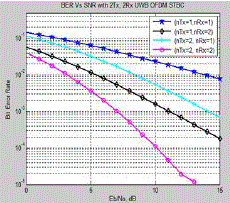
| In UWB environment the rake receiver can use more bits than other technology. Channels such as Rayleigh and white Gaussian noise are used. Data is sent via multipath where addition of noise takes place in channel. Receiver has hard decision coding. The obtained Output has SNR of 25dB but BER greater than 0.1 which is shown in Fig.5.2. |
| According to MIMO concept, the data is sent via 2 transmitters and 2 receivers, SNR is high in all the cases. But BER decreases when data transmitted via second transmitter and second receiver. From the graph the best value for both SNR and BER is the path of data transmission via first transmitter and second receiver. |
INTERFERENCE CORRECTION
|
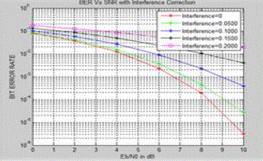
| Interference calculation takes place by declaring parameters such as number of sub-carriers=256, CP=16, FFT size=256, interference to be at the added range of 0 to 0.2 with incremental level of 0.05. Number of users is 5000. Data to be transmitted is generated and QPSK modulation is used. The modulated data is added with additive white Gaussian noise and Doppler interference. |
| Doppler interference is similar to frequency mismatch. To avoid frequency mismatch between transmitter and receiver Doppler interference is introduced. Energy detection receiver is used which gives BER of less variation within the range of 0.1. The above process is known as UWB MIMO. The BER vs. SNR interference correction graph is shown in Fig.5.3. |
ANALYSIS OF ENERGY DETECTION RECEIVER
|
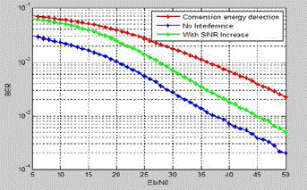
| To declare parameters such as number of antennas=4, number of subcarriers=52, block size=200, =2^8, IFFT samples=256, number of transmitter=2 and number of receiver=2. Transmission of data with QAM modulation scheme and demodulating the same data with demodulation QAM scheme. Normalization of error components has to be done to reduce error. Normalization means minimizing heavy data amplitude. The received output has achieved SINR greater than 50dB and BER less than 0.1 which is shown in Fig.5.4. |
| From the graph, it can be inferred that the energy detection receiver, no interference condition and SINR increase case has same SINR value of 52dB. |
CONCLUSION
|
| Energy detection receiver achieves SINR of 52 dB and BER of 0.07 dB using QAM-16 scheme. A hopping multiband OFDM modulation fully exploits all of the available spatial and frequency diversities. Further BER can be reduced by the use of QAM-64. But this modulation scheme has constraint in UWB-MIMO system. It has to be overcome to obtain higher SINR value.UWB is applicable with high data rate.UWB with MIMO-OFDM is suggested as the best technology to provide with high speed, data rate and reduced BER. Energy detection and Rake receiver are suggested as the best receiver for UWB applications. This paper better explain the suitable interference reduction scheme for UWB. |
Figures at a glance
|
 |
 |
 |
| Figure 1 |
Figure 2 |
Figure 3 |
 |
 |
 |
| Figure 4 |
Figure 5 |
Figure 6 |
 |
 |
 |
| Figure 7 |
Figure 8 |
Figure 9 |
|
References
|
- Estrin.D, Heidemann.J and Xu.Y, “Geography-informed energyconservation for ad hoc routing,” in Proc. 2001 ACM Mobi Com, pp.70–84.
- Harn.L, Huang.D, Medhi.D and Mehta.M, “Location-aware key management scheme for wireless sensor networks,” in Proc. 2004 ACMSASN, pp.29–42.
- Kinney.P, Molisch.A, Orlik.P, Sahinoglu.Z and Zhang.J, “UWB systems for wireless sensor networks,” Proc. IEEE, vol. 97, no. 2, pp.313–331,Feb. 2009.
- Cao.H, Chan.H, Chow.C and Leung.V, “Enabling technologies for wireless body area networks: a survey and outlook,” IEEE Commun.Mag., vol.47, no. 12, pp. 84–93, Dec. 2009.
- Althaus.F, Steiner.C, Troesch.F and Wittneben.A, “Ultra-wideband geo-regioning: a novel clustering and localization technique,” EURASIP J.Adv. Signal Process., Nov. 2007.
- Burger.T,Steiner.C,Troesch.F,Wittneben.A and Zasowski.T, “Hardware aware optimization of an ultra low power UWB communication system,”in Proc. 2007 IEEE Int. Conf. Ultra-Wideband, pp. 174–179.
- Giannakis.G, Luo.X and Yang.L “Designing optimal pulse-shapers for ultra-wideband radios,” J. Commun. Netw., vol. 5, no. 4, pp. 344–353, Dec.2003.
- Luecken.H, Steiner.C, Troesch.F, Wittneben.A and Zasowski.T,“Location-aware adaptation and precoding for low complexity IR-UWB receivers,” in Proc. 2008 IEEE Int. Conf. Ultra-Wideband, pp. 31–34.
- Wu.H and Zhu.Y, “Integrated distributed transversal filters for pulse shaping and interference suppression in UWB impulse radios,” in Proc.2006 IEEE Int. Conf. Ultra-Wideband.
- Chang.Y, Kuo.C, Tsai.S and Yu.X “Performance en
|