ISSN ONLINE(2320-9801) PRINT (2320-9798)
ISSN ONLINE(2320-9801) PRINT (2320-9798)
Ambarish D. Pundlik1, Anant.S. Bhide2, Tanvi P. Mahajan3
|
| Related article at Pubmed, Scholar Google |
Visit for more related articles at International Journal of Innovative Research in Computer and Communication Engineering
Here is implemented a home navigation system, which comprises of a wheelchair which works on the inputs such as gesture and voice commands via an android phone and navigates according to command. It can be used by an elderly or physically challenged person to move inside the home without any difficulty. It’s common that the elders and the physically challenged people find it hard to move the wheel chair without external aid. By making use of HNS, elderly and the physically challenged can move to different locations in the particular house just by pronouncing the direction name or by making the movement of the android phone they will be provided with. It is also equipped with obstacle avoidance technique, where the person may not be able to provide proper command at the right time. A security threat message can be sent through the mobile phone to predefined number, if the user feels to be found in danger.
Keywords |
| Wheelchair, HNS, gesture, voice commands, physically challenged, android |
INTRODUCTION |
| The most common image of disability is the people in wheelchairs. Wheelchairs are used by people who find themselves unequipped to move without external aid. The special needs of the elderly may differ from that of a physically challenged person or a large individual but they all have “special needs” and often require some assistance to perform their daily routine. The physically challenged people, who use a normal wheelchair for navigation, usually require an external person to move around. In this busy world, the elderly people may be left alone at home and also may not find an apt person for external help. Here comes the need of an automated home navigation system, which consists of a wheelchair which can be used by the elderly and the physically challenged people without the help of an external person. The proposed HNS can be operated using voices and the gestures of the provided android mobile phone. An important feature is that the personal security of the person who is using the wheelchair is also taken care. If the person feels uncomfortable or insecure, he can send a message to a predefined number using the speech to text (STT) function in the mobile phone. |
RELATED WORK |
| In [1] it is reviewed that although some current wheelchair systems have embedded computers, they have very little computer control and require precise, low-level control inputs from the user; interfaces are similar to those found in passenger cars. Authors developed a smart wheelchair with intelligent controllers that let people with physical disabilities overcome these difficulties. By outfitting the wheelchair with cameras, a laser range finder, and on-board processing, we give the user an adaptable, intelligent control system. Account of the high risk of collisions with people and objects is taken in [2]. This paper describes and presents the preliminary results of a system that uses an infrared sensor to provide anti-collision and a prompting system for a poweredwheelchair that helps guide the user safely past obstacles. Paper [3] focuses on thenavigation and guidance systemofapoweredwheelchair. We have developed anavigation module with different levels ofautonomy which realizes an active interaction ofthe user with the robotic aid. A wheelchair for physically disabled people developed within the UMIDAM I Project is explained in [4]. A dependent-user recognition voice system and ultrasonic and infrared sensor systems has been integrated in this wheelchair. In this way we have obtained a wheelchair which can be driven autonomously or with using voice commands and with the possibility of avoiding obstacles and downstairs or hole detection. Paper [5] describes the wheelchair system with user friendly touch screen interface. The ability to choose between manual operating mode and predefined operating mode uniquely presents capacity of the wheelchair to operate in multiple environments. |
PROPOSED ALGORITHM |
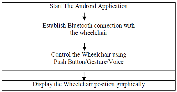
A. Flow Chart of The Voice and Gesture Based Wheelchair: |
 |
SYSTEM DESIGN |
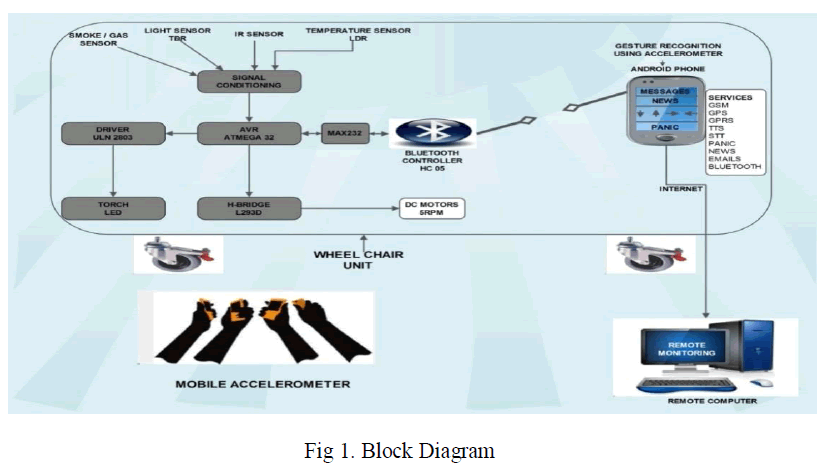
| Here we can understand the construction and working of the model. System uses an Android phone to communicate with the wheelchair and a desktop computer is used to monitor the position of the wheelchair. |
A. Hardware Description |
| The hardware consists of various components such as AVR ATmega32, a Bluetooth device, motor driver which is L293D, IC ULN2803, external device such as torch, two dc motors of 5 rpm each, MAX232 for serial communication between AVR and Bluetooth, four sensors for temperature, smoke, obstacle distance and light along with an android phone and a remote computer which are explained one by one below. |
 |
| 1. ATMega32 |
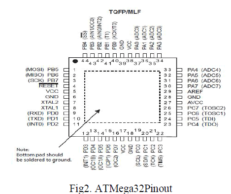 |
| Fig 2 is the pinout diagram of the ATMega32 controller. The ATmega32 is a low-power CMOS 8-bit microcontroller based on the AVR enhanced RISC architecture. By executing powerful instructions in a single clock cycle, the ATmega32 achieves throughputs approaching 1 MIPS per MHz allowing the system designers to optimize power consumption versus processing speed. |
| 2. L293D |
| L293D is a dual H-bridge motor driver integrated circuit (IC). Motor drivers act as current amplifiers since they take a low-current control signal and provide a higher-current signal. This higher currentsignalis used to drive the motors. |
| Fig 3 below is the pin diagram of L293D. Enable pins 1 and 9 (corresponding to the two motors) must be high for motors to start operating. When an enable input is high, the associated driver gets enabled. As a result, the outputs become active and work in phase with their inputs. Similarly, when the enable input is low, that driver is disabled, and their outputs are off and in the high-impedance state. |
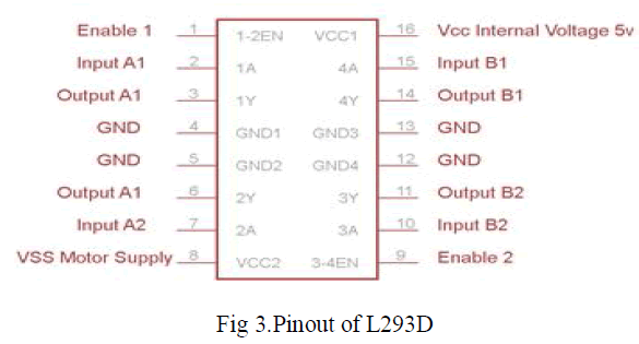 |
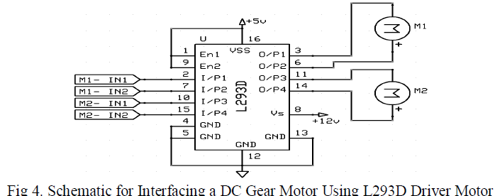
| Generally, L293D motor driver can control two motor at one time or called is a dual H-Bridge motor driver. By using this IC, it can interface DC motor which can be controlled in both clockwise and counter clockwise direction. The motor operations of two motors can be controlled by input logic at pins 2 & 7 and 10 & 15. Below is shown the pin diagram of L293D motor driver. |
| Besides that, with this L293D driver motor it will control four DC motors at one time but with fix direction of motion. L293D has output current of 600mA and peak output current of 1.2A per channel. Moreover for protection of circuit from back EMF output diode are included within the L293D. The output supply which is external supply has a wide range from 4.5V to 36V which has made L293D a best choice for DC motor driver. A simple schematic for interfacing a DC gear motor using L293D driver motor is shown below: |
 |
3. MAX232: |
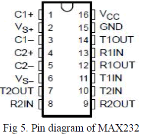
| The MAX232 IC is used to convert the TTL/CMOS logic levels to RS232 logic levels during serial communication of microcontrollers with PC. The controller operates at TTL logic level (0-5V) whereas the serial communication in PC works on RS232 standards (-25 V to + 25V). This makes it difficult to establish a direct link between them to communicate with each other. The intermediate link is provided through MAX232. Below fig 5 is the pin diagram of MAX232. |
 |
4. ULN2803: |
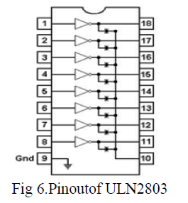
| Featuring continuous load current ratings to 500 mA for each of the drivers, the Series ULN28xx high voltage, high-current Darlington arrays are ideally suited for interfacing between low-level logic circuitry and multiple peripheral power loads. Typical loads include relays, solenoids, stepping motors, magnetic print hammers, multiplexed LED and incandescent displays, and heaters. All devices feature open-collector outputs with integral clamp diodes. Please refer fig 6 below for the pin description of the ULN2803. |
 |
| 5. Sensors: |
| There are four sensors used- proximity, smoke, temperature and light. Proximity and smoke detection uses Infrared technique, temperature is detected by thermistor and light using LDR. |
| 6. HC 05 Bluetooth to serial port module: |
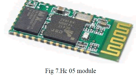 |
| HC-05 module is an easy to use Bluetooth SPP (Serial Port Protocol) module, designed for transparent wireless serial connection setup. Serial port Bluetooth module is fully qualified Bluetooth V2.0+EDR (Enhanced Data Rate) 3Mbps Modulation with complete 2.4GHz radio transceiver and baseband. It uses CSR Bluecore 04-External single chip Bluetooth system with CMOS technology and with AFH(Adaptive Frequency Hopping Feature). It has the footprint as small as 12.7mmx27mm. Hope it will simplify your overall design/development cycle. Fig 7 is the Hc 05 module image. |
7. Power Supply Unit |
| The +5 volt supply is useful for both analog and digital circuits. DTL, TTL, and CMOS ICs will all operate nicelyfrom a +5 volt supply. In addition, the +5 volt supply is useful for circuits that use both analog and digital signals invarious ways. More importantly for our purposes, the +5 volt supply will be used as the primary reference for regulating all of the other power supplies we will build. We can do this very easily if we useoperational amplifiers as thecontrolling elements in the power supply circuits. |
 |
| The +5 volt power supply is based on the commercial7805 voltage regulator IC. This IC contains all the circuitry needed to accept any input voltage from 8 to 18 volts and produce a steady +5 volt output, accurate to within 5%(0.25 volt). It also contains current-limiting circuitry and thermal overload protection, so that the IC won't be damaged in case of excessive load current; it will reduce its output voltage instead. |
B. Circuit Diagram: |
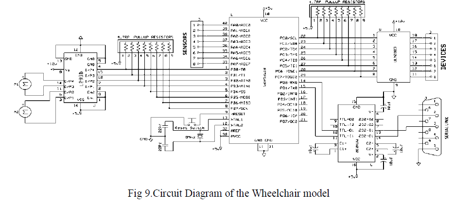 |
| We have already discussed the working of the components which can be seen in the circuit diagram. This is all about the hardware part of the wheelchair model. Next we’ll discuss the software part of the system. |
C. Software Description: |
| In the Software part of this system, first comes the android. Which is a Linux-based operating system primarily designed for mobile devices such as smartphones and tablet computers utilizing ARM processors, Uses Java as the programming language. NetBeans are well known to construct the Graphical User Interface of the android application. Lastly to communicate to a remote monitoring desktop, Servlets are used. |
PERFORMANCE ANALYSIS |
A. Performance Analysis of the System |
| There are four GUI (Graphical user interface) screens in this android application. Working of each is explained below- |
| Screen 1- Enter the IP address of remote monitoring desktop (Refer fig 10) |
| Screen 2- url of the news website, email id and password (Refer fig 11) |
| Screen 3- To connect via Bluetooth to wheelchair (Refer fig 12) |
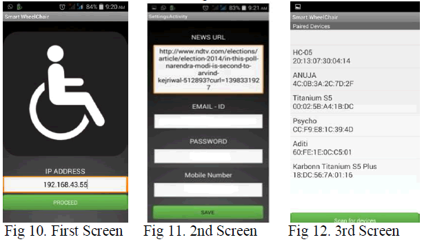 |
| GUI screens of the Android Application |
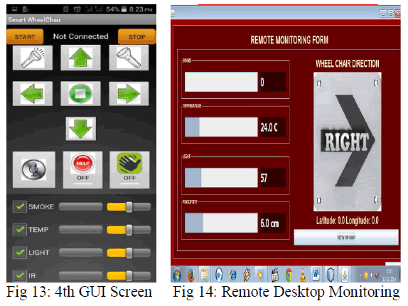
| On the fourth screen (refer fig 13), actual operation of the wheelchair is controlled. Here the movement of wheelchair is controlled in three modes- Push buttons, Gesture of the handset and voice. Buttons for sending a help seeking message and torch are also provided. |
 |
Monitoring on remote Desktop: |
| Here on the remote desktop (refer fig 14), we can monitor the four sensor values as shown in above photo. Secondly, the current movement of the wheelchair and the latitude and longitude positions can be observed. Along with this, a link to Google Map is given which can shows the position of the wheelchair on the Google map. |
CONCLUSION |
| Here we have tried to render a wheelchair for both elderly and the physically challenged with a varied physical disability. Android phone has become a part of day to day life. Having the same is no more a rare thing. Hence Android phone is used as the medium of communication with wheelchair. |
FUTURE SCOPE |
| The remote monitoring desktop shows the direction in which the patient is moving. This direction indication can be replaced by the actual image of the wheelchair by using a camera on the wheelchair. |
References |
|