Three-phase boost-inverter consists of three DC-to-DC boost converters with a common point and operates with boosting capability to feed three-phase star connected Load. The main advantage of that inverter is the use of only six IGBTs and small passive elements to obtain an AC output larger than the DC input. This inverter can amplify power sources such as fuelcells, small turbines, and photovoltaic arrays (i.e. it is suitable for distributed power applications). In this paper, two main contributions are presented; first is applying the third harmonic injection scheme to increase the boost-inverter gain. This method permits 15% increase in the output voltage without causing any distortion to line-to-line voltages. Second one studying performance of the grid connected boost-inverter. Simulation and experimental results show the effectiveness of that inverter in grid connection applications.
Keywords |
| Boost-inverter, Third harmonic injection, Grid connected inverters, Distributed power |
INTRODUCTION |
| The conventional voltage source inverter is probably the most important power converter topology. It is used in many distinct
industrial and commercial applications. One of the characteristics of the conventional inverter is that the instantaneous output
voltage is always lower than the input DC voltage. As a result, when an output voltage larger than the input one is needed, a
boost converter must be used between the DC source and the inverter. |
| A single-phase voltage source inverter (single phase boost-inverter) is proposed by Ramón Cáceres and Ivo Barbi [1],[2].
The single stage boost-inverter can generate an output AC voltage larger than the input DC voltage depending on the duty cycle
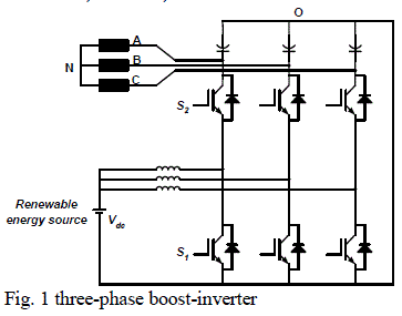
[3].A novel three-phase boost-inverter is proposed in [4], the system consists of three DC to DC bi-directional boost converters
with a common point (O) as shown in Fig 1. These converters produce a DC biased sine wave output. The AC component of
each converter is 120 degrees out of phase with the other, the main advantage is the use of only six IGBTs with small passive
elements to generate an output AC voltage larger than the input DC voltage (i.e. this system can amplify power sources such as
renewable energy sources). The main contributions of this paper are: |
| •Applying the third harmonic injection technique to increase the gain of boost-inverter. |
| •Studying the performance of grid connected three-phase boost-inverter. |
| This paper is organized as follow: Section I gives the Introduction of boost-inverter nature. Section II is helpful to understand
the principles of boost-inverter topology. Section III explains how to extend the gain of boost-inverter by third harmonic
injection. Section IV shows the performance of three-phase grid-connected boost-inverter. Section V validates the concept
experimentally, and the last section VI concludes the paper and followed by the references. |
 |
 |
PRINCIPLE OF OPERATION |
| Each phase in the three-phase boost-inverter consists of two IGBTs, one inductor and one capacitor. There is a common point
for capacitors (O) which connected with the negative terminal of the DC supply. The load is connected to inverter terminals and
creates another common point (N) which must not be connected to capacitors common point. |
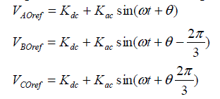
| The reference voltage of each capacitor has two components: |
| •DC component (Kdc): is the same for all phases and it must be greater than the summation of AC component peak (Kac)
and DC input voltage (Vdc). |
| •AC component: AC component of each converter is with the same magnitude but 120 degrees out of phase with the
other converters. As shown in (1) |
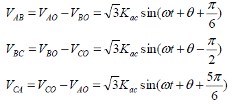
| The load is connected differentially across the capacitors (Fig. 1) to prevent DC component from appearing across the load
terminals. Eq (2) shows the converter output line-to-line voltages which can feed any three-phase load. |
  |
| For phase-A, the output voltage relation for the continuous conduction mode can be obtained as in (3), where D is the duty
cycle of DC-to-DC converter. To get VAOref across the capacitor of phase-A, the instantaneous value of reference duty cycle for
this phase can be obtained from (4), |
  |
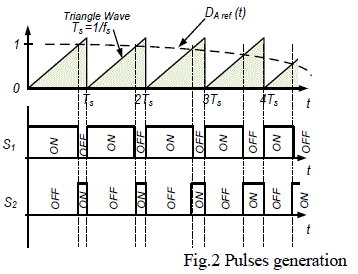
| PWM pulses can be generated easily as shown in Fig. 2 where fsis the switching frequency of the inverter. This can be done
similarly to phases B and C.MATLAB/SIMULINK package is used to build a model for the three-phase inverter circuit. By
adjusting the model parameters with values shown in table I, the simulation results will be as shown in Fig. 3.Fig 3b shows that
the AC component of VAO(t) is unsymmetrical due to duty cycle variation; the capacitor voltage ripples in boost converters are
linearly dependent on value of duty cycle. This asymmetry means that there is an even harmonic component in the output
voltage. Fig. 3c shows the values of even harmonics relative to the fundamental component, it has to be noted that the even
harmonics values are within the acceptable limits and less than the IEEE standard values [5]. |
THIRD HARMONIC INJECTION |
| Harmonic injection can be used to produce flat-topped phase waveforms which improve the efficiency of the inverter [6-8].
This method has potential for extending the rating of all PWM inverters (increase the output voltage of an inverter). The
method involves the addition of third harmonic to the AC component. Third harmonic in a three-phase supply is eliminated
from the line-to-line waveforms. |

TABLE I. Three-phase Boost-inverter Parameters |
 |
| The addition of one-sixth of third harmonic to the AC component has the effect of reducing the peak by a factor of 0.866
without changing the amplitude of the fundamental [9]. This process is illustrated in Fig. 4. It is then possible to increase the
amplitude of the modulating wave by certain factor so that the full output voltage range of the inverter is again utilized. By
adjusting this factor, the peak of the AC component can equal unity. From Fig. 4 the previous peak was 0.866. Therefore |
 |
| Thus as Fig. 4 shows, the addition of one-sixth of third harmonic produces a 15% increase in the amplitude of the fundamental
of the phase voltage waveform and, therefore, in the line voltage waveform. The line-to-line waveform is undistorted since the
third harmonic components in the phase waveforms will be cancelled. |
| For DC supply of 100V and DC component of 250V, without Harmonic injection, output phase voltage magnitude up
to 150V can be obtained, i.e. 150V is the maximum allowable voltage. |
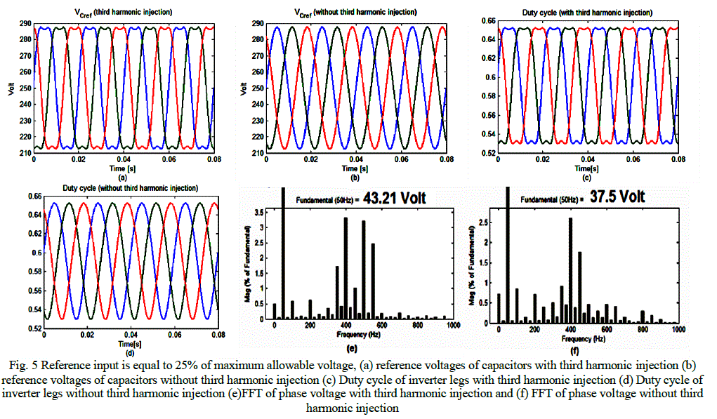
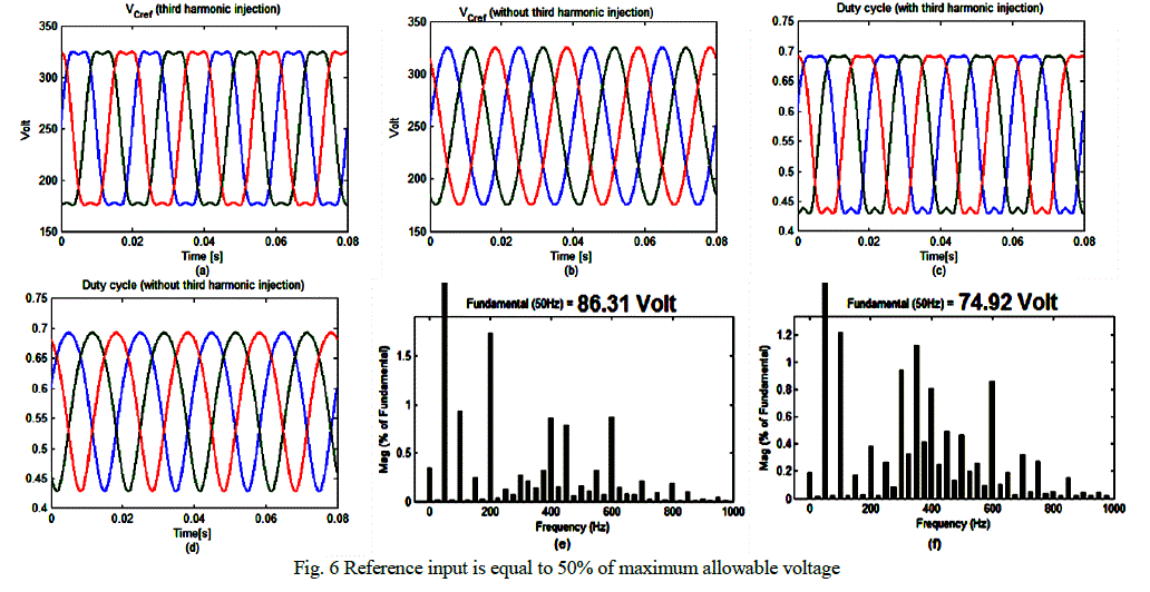
| In case of third Harmonic injection output phase voltage magnitude up to 172.5V (1.15*150V) can be obtained. The simulation
results for reference input equal to 25% and 50% of maximum allowable voltage are shown in Fig. 5 and 6 respectively. The
output voltage is applied across three-phase resistive load (30 ohm per phase). The simulation results are summarized in table II.
The simulation results confirmed that, it is possible to increase the output voltage of a three-phase boost-inverter by adding a
third harmonic to AC component. The maximum increase in output voltage is obtained when the amplitude of the third
harmonic is one-sixth that of the fundamental. The method permits 15% increase in the output voltage. |

TABLE II.Magnitude of output phase voltage |
GRID CONNECTED MODE |
| Renewable energy sources require the DC-AC conversion stage meet grid voltage and frequency requirements. In island mode,
the inverter regulates the AC bus voltage and frequency to master the AC load. When the grid is restored, the inverter should
retain the grid-connection operating mode, where the grid masters the bus voltage and frequency. |
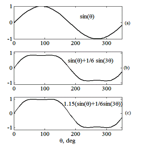
Fig. 4. Increasing fundamental output voltage by addition of third harmonic. |
 |
 |
 |
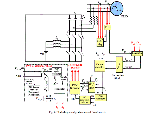
| Fig. 7 shows the block diagram of the grid-connected boost-inverter. Pref and Qref are used to determine the desired
current components (igd ref, igq ref) that govern the power flow. A saturation block is used to define the limited overload capability
of the inverter. The maximum allowable current is adjusted to be 1.5 times the full load current as the inverter switches cannot
be overloaded. Then, a current controller is used to obtain the AC component of capacitor reference voltage (PI current control
in synchronous reference frame). Then, a suitable DC component is added to the AC component to obtain the inverter reference
voltage. The DC component is selected to guarantee proper operation at unity modulation index (minimum THD), i.e.
Kdc=Kac+Vdc.The option of injecting third order harmonic component is shown in Fig.7 at the per-phase PWM generator subsystem. |
| A MATLAB model has been built with data shown in Table III. The performance of the grid-connected boost-inverter
during normal as well as abnormal conditions is studied. |
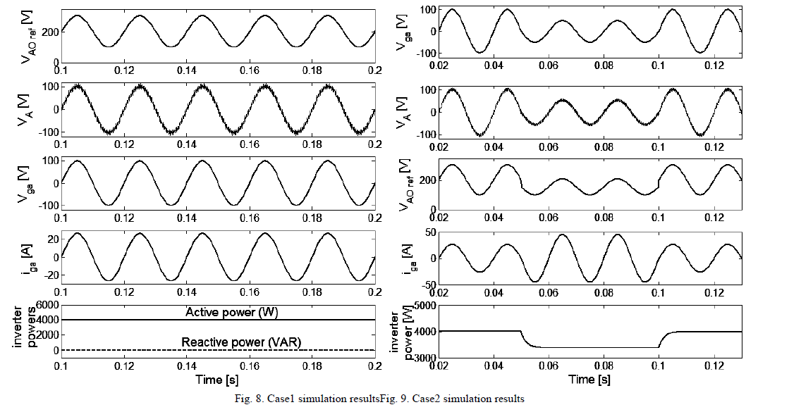
| Case1: This case studies the performance of the boost-inverter during normal/healthy conditions. Active and reactive power
orders are adjusted to 4kW and 0 VAR respectively, the simulation results are shown in Fig. 8. |
| Case 2:in this case the performance of boost-inverter is tested during faulty condition, a remote fault is applied in the grid that
leads to 50% voltage sag at t=0.05s and is cleared at t=0.1s. It is expected that the fault level increases at the specified fault
location but due to the limited overload capability of the inverter, the reference voltage is decreased automatically to limit the
fault current to 1.5 times the full load current. The simulation results for this case are shown in Fig. 9. The simulation results
show the effectiveness of boost-inverterin grid connected applications. Since it has a boosting capability it will be suitable for
integrating the renewable energy sources to the grid. In addition, it has a sinusoidal output voltage, i.e. the need of AC output
filters is eliminated. |
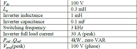
Table III. Grid-connoted boost-inverter parameters |
 |
 |
EXPERIMENTAL SETUP |
| An experimental setup was built (Fig. 10) to: |
| •Validate the normal operation of boost-inverter and show its boosting capability in island mode. |
| •Exploring the effect of third harmonic injection on its range extension. |
| •Assess the performance of grid-connected boost-inverter during normal operating conditions. |
| The experimental setup consists of a three-phase inverter employing six IGBTs driven by a high voltage driver, three capacitors,
three inductors, resistive load and DC supply. The firing pulses of 3 kHz switching frequency are generated from Texas
Instrument DSP TMS320F28335 to obtain desired phase voltage.
Following tests are applied: |
| Test I: To validate the normal operation of boost-inverter, parameters of the setup are adjusted as in table IV. The experimental
results are shown in Fig. 11a and 11b. It is obvious that the experimental results validate the boost-inverter concept.c |
| Test II: An extended gain boost-inverter is tested by injecting third harmonic order to the AC component. The corresponding
experimental results are shown in Fig. 11c. It is obvious that the Inverter gain was extended by 15% without distorting the
output voltage. |
| Test III: The performance of a grid-connected boost-inverter during normal operating conditions was also tested
experimentally. In this mode, the boost-inverter was used to inject a certain amount of power (30W, 0VAR) to the grid. Fig.
11d shows the inverter output voltage which is coupled to the grid via an interface reactance. The grid supplied current is shown
in Fig. 11e, it is obvious that the grid supplied current is negative with respect to its voltage, i.e. the power (30W) is injected to
the grid. |
 |
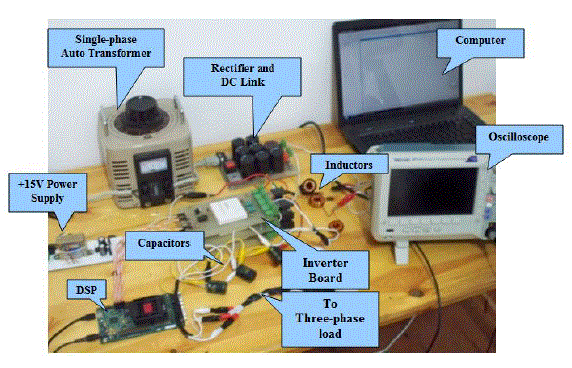
Fig. 10 Three phase boost-inverter Experimental setupc |
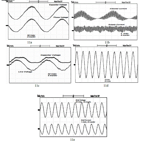
Fig. 11 (a) Test I: capacitor and phase Voltage (b) Test I: inductor and supply currents, (c) Test II: capacitor and line voltage, (d) Test III: boost-inverter
output voltage and (e) Test III: grid voltage and current. |
CONCLUSION |
| This paper deals with three-phase boost-inverter which is suitable for transferring a specific amount of renewable power to AC
loads (low cost distributed inverters). The main contributions of this paper are: |
| •Applying the third harmonic injection technique to increase the gain of boost-inverter by 15%. |
| •Studying its performance when connected to the grid. |
| Simulation and experimental results show the effectiveness of the grid connected boost-inverter during normal operating
conditions (transfers renewable power to AC loads). It will be also effective during the abnormal conditions since it contributes
with limited fault current due to the maximum current limit in its current controller. |
ACKNOWLEDGMENT |
| This publication was made possible by NPRP grant NPRP 4 - 250 - 2 – 080 from the Qatar National Research Fund (a member
of Qatar Foundation). The statements made herein are solely the responsibility of the authors. |
References |
- Ramon O. Caceres and Ivo Barbi "A Boost DC–AC Converter: Analysis, Design, and Experimentation", IEEE Transactions on Power Electronics Vol.14 , No. 1, pp.134-141, January 1999.
- Minsoo Jang, M. Ciobotaru, V.G. Agelidis, “A single-phase grid-connected fuel cell system based on a boost-Inverter”, IEEE Trans. On powerElectron., vol. 28, no. 1, pp. 279 – 288, Jan. 2013.
- Pablo Sanchis, Alfredo Ursæa, Eugenio Gubía and Luis Marroyo "Boost DC–AC Inverter: A New Control Strategy," IEEE Transactions on PowerElectronics, Vol. 20 , No. 2 ,pp.343-353 ,March 2005.
- Carlo Cecati , Antonio Dell’Aquila, and Marco Liserre "A Novel Three-Phase Single-Stage Distributed Power Inverter," IEEE Transactions on PowerElectronics, Vol. 19 , No. 5 ,pp.1226-1233 ,September 2004.
- S. M. Halpin "Comparison of IEEE and IEC Harmonic Standards," IEEE Power Engineering Society general meeting, 2005, Vol. 3,pp.2214-2216, June2005.
- Michael A. Boost and PhoivosD.Ziogas "State-of-the-Art Carrier PWM Techniques: A Critical Evaluation," IEEE Transactions on Industry Applications,Vol. 24, No. 2 ,pp.271-280, March 1988.
- Vassilios G. Agelidis, Phoivos D. Ziogas, and GezaJoos "“Dead-Band’’ PWM Switching Patterns," IEEE Transactions on Power Electronics, Vol.11 ,No. 4 ,pp.522-531 ,July 1996.
- Vladimir Blasko "A Hybrid PWM Strategy Combining Modified Space Vector and Triangle Comparison Methods," 27th IEEE Power ElectronicsSpecialists Conference, Vol.2, pp.1872-1878, June 1996.
- John A. Houldsworth and Duncan A. Grant "The Use of Harmonic Distortion to Increase the Output Voltage of a Three-Phase PWM Inverter," IEEETransactions on Industry Applications ,Vol. IA-20 ,No. 5 ,pp.1224-1228, September 1984.
|