Keywords
|
| Fault protection, phase-locked loop (PLL), power system, transients, Fuzzy Logic Controller(FLC). |
INTRODUCTION
|
| The protection is very much important task in a power system to get uninterrupted power supply. Generally a power system should be protected from abnormal conditions such as faults, transients etc. In power system protection both the fault detection as well as fault discrimination has equal importance. In some type of system the discrimination of fault is very much essential one. The discrimination can be done by various types of techniques such as time domain analysis, wavelet transform, equivalent instantaneous inductance technique, absolute difference of active power technique for discrimination in various equipments as well as in whole power system. Thus the protection of power system is very much essential to avoid the block out of power supply and avoid losses due to the unnecessary power disconnectivity. |
| Strong Power System: The system which has low impedance between source and load and cause very less disturbance to the source during the faults, called strong power system. Most of the industrial systems are strong power systems. They desire high short circuit power to connect and disconnect loads without causing disturbances to sensitive equipment or processes. With the high short-circuit power, a high fault current develops in case there are faults in the system. This high fault current has to be considered when designing the switchgear and other components that build up the power system. This is easily done in new installations but can be problematic when there is a need for higher shortcircuit power in an existing system. In these cases, the installation of a fault current limiter could be an alternative to rebuilding the switchgear. The installation of a fault current limiter can also provide the opportunity to make connections in the power system that otherwise would not be possible due to fault currents that exceed the rating of the switchgear. Power system protection is another important issue. It is essential for safe operation of the power system that faults are detected and cleared automatically in a fast and reliable manner so that the operation of the power system is not disturbed. A typical fault protection system is built from circuit breakers (CBs), protection relays, and primary transducers, such as voltage and current transformers and auxiliary equipment. There are many methods and algorithms available to detect short-circuit current in a power system. One simple (but yet efficient) method is to estimate the current from measured current samples. If the magnitude of the estimated current is larger than a predetermined threshold it is assumed that a fault has occurred (magnitude relay). The estimation of the current can be performed using several different techniques, such as, for example, by calculating the root mean square (rms) value, or by a Fast Fourier transform (FFT) method, or by a least-square (LSQ) method. The accuracy of the estimation and the amount of information that is available for the estimation are correlated. In general, if more information is available, the estimation will become more accurate. On the other hand, if faster fault detection is required, the estimation becomes less accurate since less information is available. |
| Even though the detection of faults is the primary concern for fault protection devices (dependability), the ability to distinguish between a fault and a switching transient (security) is also important. Switching transients can, under certain circumstances, give rise to high currents, which are much larger in magnitude than normal load currents. In existing relay protection, capacitor energization and transformer energization have been detected by analyzing the measured current to find certain characteristics of the two types of current transient. A current transient caused by a transformer energization typically contains a superimposed dc component and a superimposed second harmonic component. A current transient caused by a capacitor energization typically contains higher frequency harmonic components. The harmonic components in the measured current can be identified with Fourier-based methods, but that typically requires more time. So to minimize the fault discrimination time PLL logic has been applied as a proposed algorithm. |
PHASE LOCKED LOOPS
|
| In this section, the proposed method of using a PLL for discrimination between faults and switching transients will be de-scribed. First, a short description of the basics of a PLL is given. Second, a well-known implementation of a PLL suitable for simulation purposes is described and the relevant signals that are used for the actual discrimination between a fault and a switching transient are identified. Third, the tuning of the parameters of the PLL implementation is discussed and suggestions for a first selection of parameters are given. |
 |
A. Basics of a PLL
|
| The PLL has been an important device in electronics and power system applications ever since the first implementation in the 1930s by de Bellescize, as mentioned in [9]. The first PLLs were analog devices but following the development in solid-state electronics and computer technology, the PLL has developed from an analog device via digital implementations to pure software implementations. |
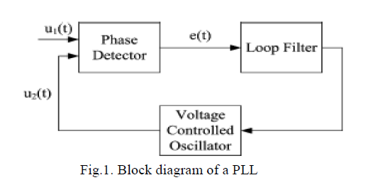
| A PLL is a circuit that is used to synchronize an input signal with a reference signal (an output signal that is generated by the PLL) with respect to phase and frequency. The function of the PLL can be explained from the block diagram of a simple PLL, as shown in Fig. 1. |
| The input signal u1(t) is compared with the reference signal u2(t) in the phase detector (PD). The output of the phase detector is zero as long as the input signal and the output signals are equal in phase and frequency. If the phase or frequency of the input signals changes, the output of the phase detector will deviate from zero. The error signal is passed through a low-pass filter (LF) and then to a voltage-controlled oscillator (VCO), which generates a reference signal (the output signal). If the error signals are deviates from zero, the VCO will adjust the frequency of the reference signal so that the phase error becomes zero and the two signals are in phase. When the input signal is in phase with the reference signal, the PLL is in its locked state; hence the name phase locked. |
B. Description of a PLL that is Suitable for the Discrimination between a Fault and a Switching Transient
|
| A vector implementation, as shown in Fig. 2, of a PLL is de-scribed in this paragraph. Compared to the block diagram of Fig. 1, the error signal e(t) corresponds to the output of the PD, whereas the fuzzy logic controller (FLC) and the derivator correspond to the loop filter and the voltage-controlled oscillator (VCO). The inputs to the PLL are the three phase-currents are projected onto a reference frame. Depending on the proximity of the αβquantities to the reference frame, an error signal is formed. This error signal is fed through a PI regulator so that the error is controlled to zero. Once the error signal is zero, the input signals are in phase with the reference frame. |
| If it is assumed that the system is in steady state and that the power system is completely balanced, the phase currents can be written as |
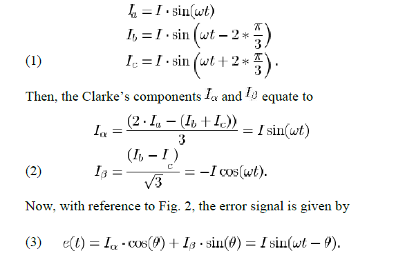 |
| Thus, the error is zero exactly when the output angle of the PLL is in phase with the current of phase a. When a transient occurs in the system, the error signal should be deviate from zero. Depending on the characteristics of the transient, the deviation will have different magnitude and frequency. Since a fault is typically an ac fundamental power frequency character, the deviation will be different than for a switching transient that contains non fundamental power frequency components. The behavior of the error signal of the PLL will also depend on the tuning of the PLL. |
C. Tuning of the PLL
|
| The PLL will be tuned to the power system frequency. PLLs have been used for many years in HVDC transmission in order to synchronize the firing of the thyristors to the phase angle of the connected ac system. It is thus a well-known procedure and it is advisable to use parameters from such an installation as a starting point for the tuning. Fine tuning of the parameters can than be made by for example, computer simulations or any other standard tuning method. |
D. Fault Detection and Discrimination Using a PLL
|
| The method that is used to detect a fault and discriminate the fault from a switching transient is described here. Two algorithms are executed in parallel. The first algorithm is based on the estimation of the magnitude of the current. If the esti-mated magnitude is higher than a preselected threshold, a flag is set. The second algorithm is as previously mentioned, monitoring the error signal of a PLL. If this error signal exceeds a preselected threshold, a second flag is set. If the both flags are set, it is to be determined that a fault has been occurred. |
DESIGN OF FLC
|
A. Design of FLC
|
| The FLC which is shown in above diagram has to be designed using fuzzy toolbox. The design starts with assigning the mapped variables inputs/output of the fuzzy logic controller (FLC). The first input variable to the FLC is the error e(t) and the second is change in error Δe(t). The output variable to the FLC is the current. |
B. Membership Functions
|
| After choosing proper variables as input and output of fuzzy controller, it is required to decide on the linguistic variables. These variables transform the numerical values of the input of the fuzzy controller to fuzzy quantities. The number of linguistic variables describing the fuzzy subsets of a variable varies according to the application. Here five linguistic variables for each of the input and output variables are used to describe them. Table 1 shows the Membership functions for fuzzy variables. |
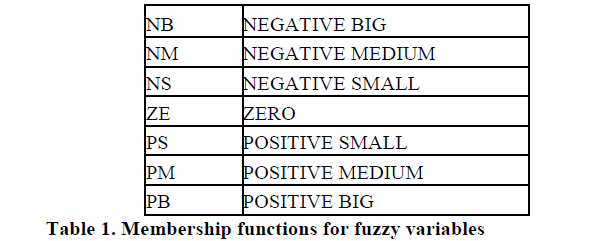 |
| The membership function maps the crisp values into fuzzy variables. The triangular membership functions are used to define the degree of membership. Here for each input variable, seven labels are defined namely, NB, NM, NS, ZE, PS, PM and PB. Each subset is associated with a triangular membership function to form a set of seven membership functions for each fuzzy variable. |
PROPOSED METHOD
|
| In order to test the proposed method, a simple test system has been developed and implemented in a MATLAB/Simulink |
 |
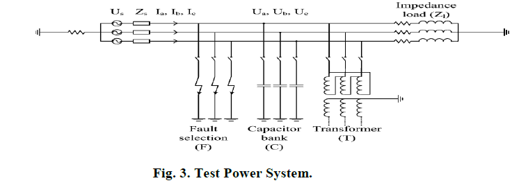 |
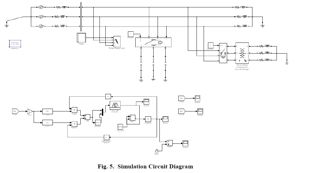
| The test power system, as shown in Fig. 3, consists of an infinite source, an impedance load, a shunt capacitor (with an associated circuit breaker), a transformer (with an associated CB), and a fault selection arrangement. The data of the system are summarized as follows. |
 |
 |
| • The transformer is modeled by a transformer model available in the master library of MATLAB/Simulink. With this transformer model, it is possible to model inrush phenomena and magnetizing properties. The transformer is connected to the power system with a CB which, at the start of the simulation, is open. The transformer is connected in delta on the primary side and in Y on the secondary side. The winding voltages of the transformer are 12 kV at the primary side and 240 V at the secondary side. Then the leakage reactance is 0.122p.u. on a transformer rating of 10.2MVA. The residual flux in the transformer is also modeled. |
| • The fault selection arrangement is implemented by using a component from the MATLAB/Simulation master library. With this component, it is possible to simulate different fault resistances, whose phases participate in the fault and different fault inception angles. At the start of the simulation, no fault is applied. |
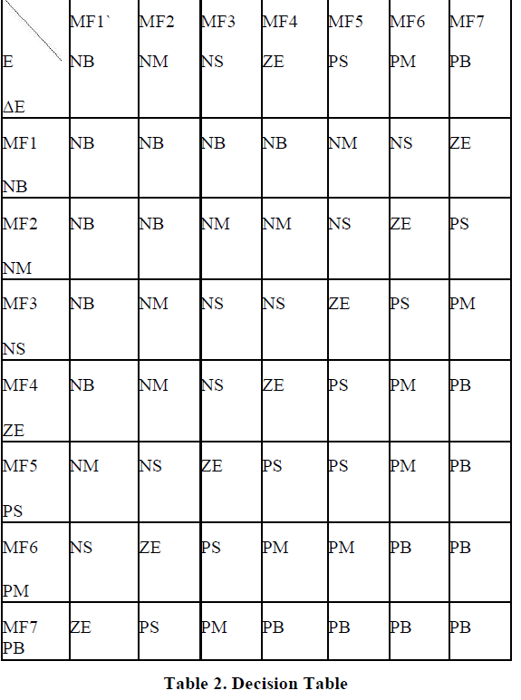
| Knowledge base involves defining the rules represented as IF - THEN rules statements governing the relationship between input and output variables in terms of membership functions. In this stage the input variables speed deviation and acceleration are processed by the inference engine that executes 7×7 rules represented in rule Table 2. |
 |
SIMULATION CIRCUIT
|
| A large selection of shunt faults, capacitor energizations, and transformer energizations have been simulated. The faults were simulated as three-phase faults and phase-to-phase faults with low impedance. This selection was made because these types of faults are dimensioning for fault-current-limiting applications. Many distribution systems are earthed through impedance, which limits the magnitude of fault currents due to single-phase earth faults. The capacitor and transformer energizations have been simulated by closing the associated CB. All events have been simulated to occur at various times with respect to the phase angle of the supply voltage (the phase angle of phase α has been selected as a reference). The instant when the event occurs will determine some of the characteristics of the transient current such as, for example, the magnitude and possible dc offset. |
 |
RESULTS
|
| A large number of results are available as a result from the simulations. A few selected results are presented here. The figures of this subsection contain plots of power system signals—mainly voltages and currents—but also signals of the control system, such as the error signal from the PLL, which has been taken as a measure on how much the measured current deviates from the pre fault load current. |
 |
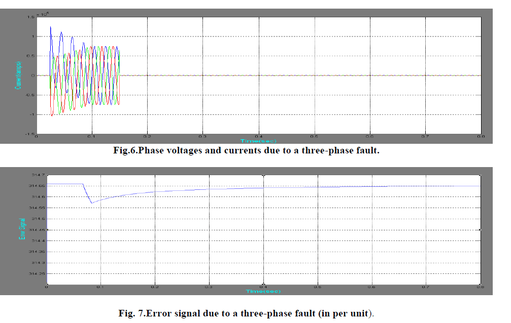 |
| Typical phase voltages and cur-rents due to a three-phase fault are plotted in Fig. 6. The error signal of the PLL for this fault is plotted in Fig. 7. As can be seen from that figure, the error signal deviates largely from zero (steady state) shortly after the fault. However, after the fault is cleared, the error signal returns to zero once the PLL has adjusted to the new conditions. Faults have been applied with different fault inception angles. The magnitude of the error signal of the PLL was well above 10p.u. for all fault inception angles. |
 |
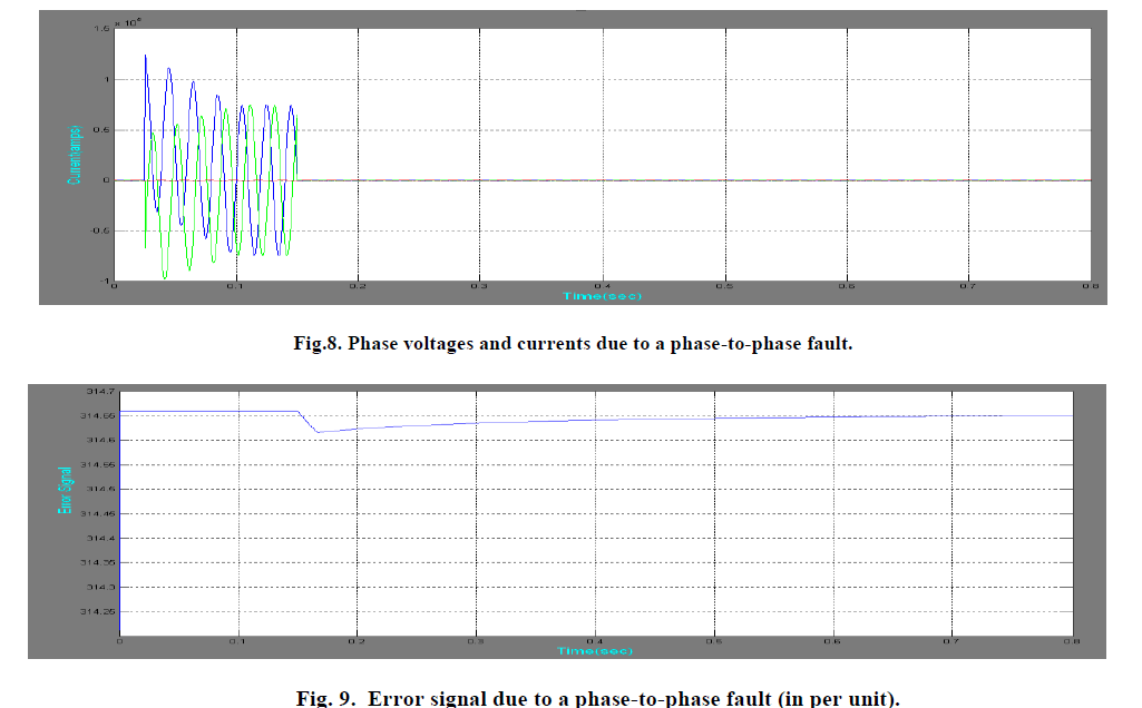 |
| Typical phase voltages and phase currents due to a phase-to-phase fault are plotted in Fig. 8. The error signal of the PLL for this fault is plotted in Fig. 9. As can be seen from that figure, the error signal again deviates from zero shortly after the fault. Once the fault is cleared, the error signal returns to zero after a short transient period. Faults have been applied with different fault inception angles. The magnitude of the error signal of the PLL was well above 10p.u. for all fault inception angles. |
 |
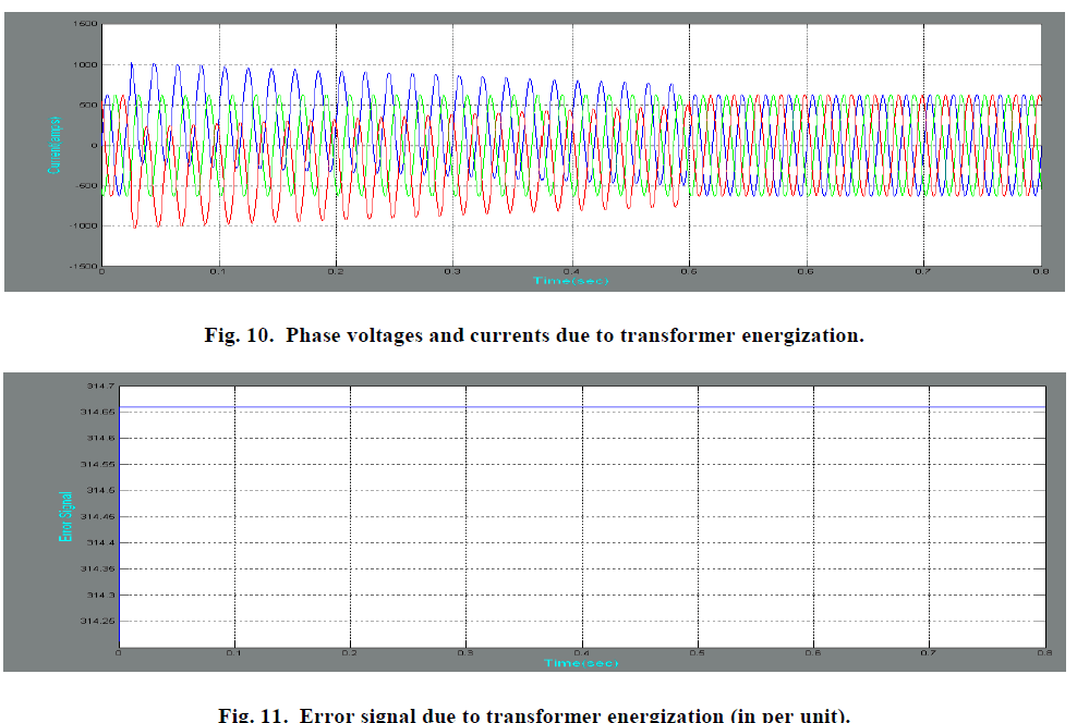 |
| Typical phase voltages and phase currents due to a transformer energization are plotted in Fig. 10. The error signal of the PLL for this event is plotted in Fig. 11. As can be seen from that figure, the error signal deviates from zero shortly after the event has occurred but returns to steady state when the PLL has adapted to the new conditions. Different switching instants were investigated and the magnitude of the error signal was never above 2p.u. |
 |
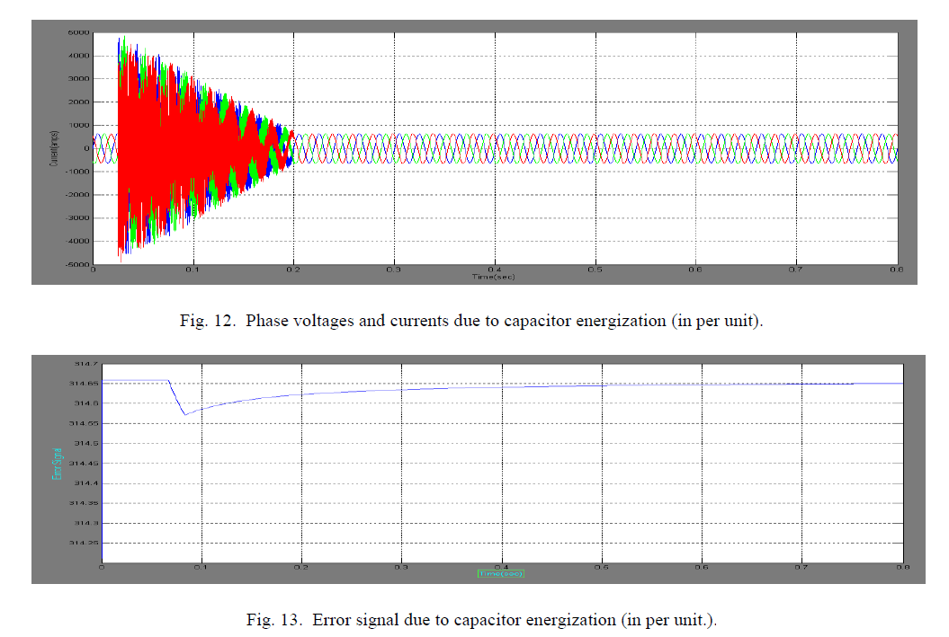 |
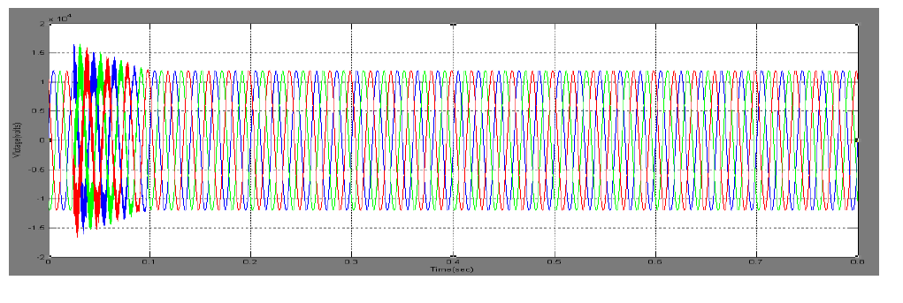
| Typical phase voltages and phase currents due to capacitor energization are plotted in Fig. 12. The error signal of the PLL for this event is plotted in Fig. 13. As can be seen from that figure, the error signal deviates from zero shortly after the event has occurred but returns to steady state when the PLL has adapted to the new conditions. Different switching instants were investigated and the magnitude of the error signal was never above 5p.u. |
CONCLUSION
|
| In this paper, it has been demonstrated that a PLL can be used to determine whether a current transient is due to a fault in the system or due to a switching transient. Transformer and capacitor switching have been specifically studied due to the large occurrence of these switching transients in the power system. Simulations have been performed using a test system where faults and switching transients have been simulated. For all of these events, a large difference was observed in the error signal of the PLL when a fault or a switching transient was applied. This difference can be used to discriminate faults from switching transients. |
References
|
- K.-H. Hartung and V. Schmidt, âÃâ¬Ãâ¢Limitation of short circuit current by an is-limiter,âÃâ¬Ãâ in Proc. 10th Int. Conf. Electrical Power Quality andUtilisation, Sep. 2009, pp. 1–4
- M. Öhrström, âÃâ¬Ãâ¢Fast fault detection for power distribution systems,âÃâ¬Ãâ pre-sented at the IASTED Conf. Power and Energy Systems, Marina delRey, CA, May 13–15, 2002
- Z. Gui-bin and G. Hou-lei, âÃâ¬Ãâ¢The current differential and travelling wave based algorithm for ultra high speed hybrid protection,âÃâ¬Ãâ in Proc. 3rdInt. Conf. Electric Utility Deregulation and Restructuring and Power Technologies, Apr. 2008, pp. 1693–1697
- T. Yang, âÃâ¬Ãâ¢A method of fast fault detection based on arma and neural network,âÃâ¬Ãâ in Proc. 6th World Congr. Intelligent Control and Automa-tion,Jun. 2006, vol. 2, pp. 5438–5441
- Sinha and A. Yadav, âÃâ¬Ãâ¢Design of hv transmission line protection and control system using wavelet transform for microcontroller applica-tion,âÃâ¬Ãâin Proc. IEEE Power India Conf., Apr. 2006, p. 5
- J. Downes, B. Gwyn, A. Johns, R. Aggarwal, and Z. Bo, âÃâ¬Ãâ¢Development and testing of a prototype fault generated noise protection,âÃâ¬Ãâ in Proc.6th Int. Conf. Developments in Power System Protection, Mar. 1997, pp. 87–90, Conf. Publ. 434
- M. Öhrström, âÃâ¬Ãâ¢Fast fault detection for peak current limitation based on few samples,âÃâ¬Ãâ presented at the 17th Int. Conf. Electricity Distribution,Barcelona, Spain, May 12–15, 2003
- G. Phadke and J. S. Thorp, Computer Relaying for Power Systems. New York: Wiley, 1988
- R. E. Best, Phase-Locked Loops—Design, Simulation and Applica-tions, 5th ed. New York: McGraw-Hill, 2003.
- G. C. Hsieh and J. C. Hung, âÃâ¬Ãâ¢Phase-locked loop techniques—A survey,âÃâ¬Ãâ IEEE Trans. Ind. Electron., vol. 43, no. 6, pp. 609–615, Dec. 1996.
|