Research & Reviews: Journal of Engineering and Technology
ISSN: 2319-9873
ISSN: 2319-9873
Anuradha M* and Vishal R
Electronics & Telecommunication Engineering Department, SavitribaiPhule, Pune University, India
Received date: 12/12/2015; Accepted date: 19/03/2016; Published date: 28/04/2016
Visit for more related articles at Research & Reviews: Journal of Engineering and Technology
Fast Fourier transforms is one of the most important frequency analysis in signal processing. It has different application such as image processing, medical field, communication system, spectral analysis etc. Butterfly is the basic elements of FFT. In this work a Distributed arithmetic technique is used to implement the butterfly module. Distributed arithmetic is Multiplierless technique resulted more efficient butterfly element both in terms of power and area. Butterfly element is the most important building block of Reconfigurable FFT processor. Single precision is used to represent the data. IEEE 754 standard is used to represent the floating point numbers.
Digital signal processing (DSP), Complex multiplier, Distributed Arithmetic, FFTs.
Fast Fourier transforms is the computation of DFT which reduces the complexity in terms of operations like multiplications & additions. The DFT and FFT results the same the only difference is that it will remove the unnecessary operations. It uses the periodicity property of twiddle terms which is mentioned after.
The FFT computation for x(n) is given by the following formula
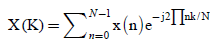 Where
Where 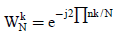 which is known as twiddle factor.
x(n)= input sequence
x(k)= output sequence
Distributed arithmetic is the Multiplier less technique is used which saves the power & area also [1]. It come into existence in 1974.FFT computation using conventional & Vedic method required the high power and area compared to distributed arithmetic technique [2]. In DA it takes only adders and shifter for operations instead of using multiplier block. Basic advantages of DA are it enables the functionality in field programmable gate array and ASICs design. It takes the advantages of look up tables. Reconfigurable is the technique in which we can useswitch to select the radix point without disturbing the hardware. It increases the flexibility [3].
A generic low power reconfigurable architecture features high efficiency in terms of area and power which is applicable to most still picture image compression standards, telecommunication protocol and automatic control [4].
Out of two algorithms DIF (discrete in time) and DIF (discrete in frequency),DIF is mostly used for implementation of FFT. This radix2 DIF FFT algorithm is starts by dividing the samples in to two groups [5]. It goes till the only computation between two samples. This two point DFT is called as Butterfly block. The butterfly is the basic block of FFT computations [6]. The diagram is given below (Figure 1).

Figure 1: Butterfly Block.
 (1)
(1)
 (2)
(2)
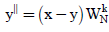
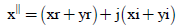
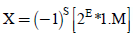
Where x and y are the input signals. Butterfly implementation is lead saving in terms of silicon area and power. The main objective of this paper is to implement the highly efficient butterfly design which could be used in reconfigurable FFT architecture. Butterfly design using distributed arithmetic technique is implemented [7]. In this architecture distributed arithmetic is used only for the butterfly implementation not the whole FFT architecture [8]. For the design of butterfly it requires two 32 bit inputs (16+16) and one twiddle factor. These numbers are represented in 16 bit floating point number which is represented in standard IEEE 754 format. We cannot be representing the number in binary form if the number is more or very less. This limitation of binary number representation removed in floating point number representation. Hence we prefer the floating point representation. Instead of using base 10 and power of 10 like in scientific notation, IEEE 754 uses binary fraction and exponent which is considered as a power of 2. The floating point reprentaion using IEEE 754 format is given below (Figure 2).

Figure 2: Floating point representation using IEEE 754 format.
Given number is in normalised form in which sign bit along with 5 bit exponent and 10 bit mantissa including 1 hidden bit (11 bit mantissa) is distinguished. Hidden bit is always taken an account in calculations. Multiplication in conventional FFT requires more power which in case of DA is completely eliminated [9]. Multiplication with twiddle factor is the main critical task in FFT computation, here in LUT based approach look up tables are prepared based on the inputs and then after proper bit adjustments and shifting these LUTs are accessed based on bit combination.
Working with 16-bit floating point numbers (imaginary and real separately) Figure 3 shows the bit manipulation happens with the 16 bit imaginary and real and imaginary part of the data. Sign bit chooses the set of LUT to be taken into account.

Figure 3: Flow of operations.
5-bit exponent bits used to equalise the number by proper biasing and then start fetching twiddles from LUTs based on mantissa bit combinations of imaginary and real numbers. These mantissa bits are obtained after shifting the mantissa bits with lesser exponent by an amount of the difference between exponents. This is explained more elaborately in the example given below [10].
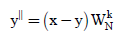
Let DAA is applied to a floating point butterfly module. Let rewrite the butterfly module equation 1 & 2
Where x and y are the input sequence which is complex numbers.
Hence
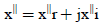
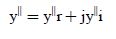
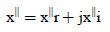
x = xr+ jxi (3)
y = yr+ jyi (4)
xr, yr = real part
Xi,yi= Imaging part
 (5)
(5)
 (6)
(6)
 (7)
(7)
Each and every real part and imaginary part of data is 16 bit IEEE 754 single precision floating point number.
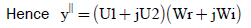
 from 3 and 4
Let xr-yr = U1and xi-yi = U2

 (8)
(8)
 (9)
(9)
Equation 8 and 9 are realized using DAA .A 16 bit number in single precision floating point is given by
S=sign bit 1 bit
M=mantissa 10 bits
E=biased exponent 5 bits and its value is given by
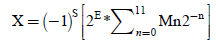 (10)
(10)
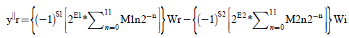
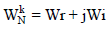
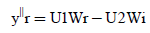
Where M1 & M2 be the 11 bit mantissa of U1 & U2 along with hidden bit which is always 1and E1=E2=E therefore
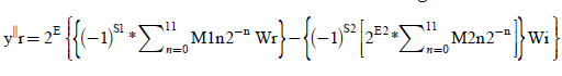

 (11)
(11)
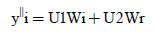
Similarly
 (12)
(12)
The value inside the braces is calculated from the look up tables which is shown below (Table 1).
| M1n | M2n | LUT value |
|---|---|---|
| 0 | 0 | 0 |
| 0 | 1 | Wi |
| 1 | 0 | -Wr |
| 1 | 1 | -Wr+Wi |
Table 1: LUT for real number calculation (S1&S2 are negative).
The value o the LUT is changes according to changes in the sign bits. The real part is calculated by using the scaled accumulator which accumulates the values from the LUT for each bit of the mantissa. Similar method is used for the imaginary part calculations.
The software implementation of Equation 11 & 12 is given below. The implementation is done by using Xilinx software and the coding is done in Verilog (Figure 4).

Figure 4: Simulation of DA butterfly using Xilinx Software.
DA based butterfly unit which as the only luring feature of tremendous power saving shows area power in Cadence RTL compiler and timing responses are observed in Modelsim (Figure 5 and Table 2).

Figure 5: Area and power reports from Cadence RTL compiler.
DA based butterfly unit which as the only luring feature of tremendous power saving shows area power and timing responses are observed. Referring to the contents of Table 2, it is quite apparent that for same reference frequency of operation DA is proved to be more power efficient compared to Vedic based approach and conventionally used multipliers. Butterfly unit is operated at 88.33MHz (Figure 6).

Figure 6: Butterfly output and calculation based on bit combination of mantissa.
| CONVENTIONAL | VEDIC | DA | |
|---|---|---|---|
| POWER | 14.2 mW | 7.2 mW | 4.8 mW |
| CELLS | 16353 | 12612 | 6612 |
| AREA | 207.6 mm2 | 223.92mm2 | 102.42 mm2 |
| FREQUENCY | 88.33 MHz | 88.33 MHz | 88.33 MHz |
Table 2: Comparison Area and power reports from Cadence RTL compiler.
Concluding the purpose of the thesis, Distributed arithmetic based multiplication is 28-30% power efficient than Vedic and compared to conventional multiplication it is beyond comparison level. Adders and shifter are the major part of the hardware and numbers of different cells used are comparatively less. Future scope of the work is to implement the whole architecture of FFT.