Keywords
|
| Cascaded H-bridge (CHB), multilevel inverter (MLI), Pulse width modulation (PWM) & Total harmonic distortion (THD). |
INTRODUCTION
|
| Two level inverter such as square wave & quasi square wave inverters are facing major problem of the lower order harmonics. Lower order harmonics are more dominant in nature while compare to higher order harmonics because of high harmonic distortion in waveform. These inverters are limited to low and medium power applications because of their limitations in increasing frequency [1]. To obtain minimum ripple content in waveform, we require high switching frequency along with multi PWM [2]. For high power high voltage applications two level inverters have some limitations in operating at high frequency mainly due to harmonics and switching losses. |
| Multilevel inverters placed big role in high power high voltage applications of electric motor drives [4], which provides stair case or stepped/PWM output voltage which is approximately sinusoidal ac output voltage with less distortion. MLIs provide better harmonic profile, reduced stress on semiconductor power electronic devices. With advancement in power semiconductor devices and converter topology, the issue of power quality becomes more significant multilevel inverters have a solution problems faced by the conventional two level inverters. |
MULTILEVEL INVERTERS
|
| There are mainly three types of MLI topologies: |
| 1. Diode clamped multilevel inverter [3] |
| 2. Flying capacitor multilevel inverter |
| 3. Cascaded H- bridge multilevel inverter [9] |
| A. Diode clamped MLI: |
| The advantages of DCMLI are: |
| i. More number of levels leads to less harmonic distortion. |
| ii. Reactive power flow is controlled. |
| iii. High efficiency for fundamental switching frequency. |
| iv. Control method is easy. |
| The disadvantages of DCMLI are: |
| i. More number of clamping diodes. |
| ii. Real power flow is difficult because of imbalance capacitances. |
| iii. Different current ratings required for switches. |
| B. Flying capacitor MLI: |
| The advantages of FCMLI are: |
| i. Flexible switch redundancy for balancing the voltage. |
| ii. Lower harmonic distortion when levels are more. |
| iii. Both real and reactive power is controlled. |
| The disadvantages of FCMLI are: |
| i. Excess number of storage capacitors. |
| ii. Inverter control is complicated. |
| iii. Switching frequency and losses are more. |
| C. Cascade H-bridge MLI: |
| The advantages of H-bridge MLI are [5]: |
| i. Switching losses and device stress is less. |
| ii. Least number of components are required. |
| iii. Potential of electric shock is less. |
| The disadvantages of H-bridge MLI: |
| It is limited to certain applications because separate DC sources are required |
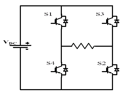 |
| Fig.1. H-Bridge inverter |
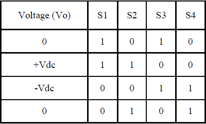 |
| TABLE. I SWITCHING STATES OF THREE LEVEL CHB |
 |
| TABLE II TOTAL NUMBER OF COMPONENTS REQUIRED FOR DIFFERENT TYPES OF MLIs |
| From above all discussion we can conclude that in all these topologies CHB topology is advantageous because of individual dc voltage sources which are available like batteries and fuel cells. In diode clamped MLI excess clamping diodes are required as number of levels increases clamping diodes requirement increases rapidly and it is difficult to control the power flow in flying capacitor MLI excess numbers of storage capacitors are required and it is difficult to maintain voltage balance in between capacitors. Now coming to required total number of switches for same level are more in diode clamped and flying capacitor because of clamping diodes and storage capacitors. This paper deals with different levels like three, five, seven, nine level topologies of CHB MLI and comparisons of THD of each inverter. By increasing no of levels we can reduce the total harmonic distortion for power quality improvement we have to reduce the harmonic content to meet the minimum harmonic distortion level of IEEE-519 [7].The harmonic content decreases as the number of levels increases and filtering requirement reduces. This paper presents detail enhancement of simulation results of different levels CHB inverter [6] and comparison of THD between them. |
POWER QUALITY
|
| Power quality places a major role in electrical drives applications. This is characterized by parameters that express harmonic pollution, reactive power, poor power factor and load unbalance. Best electrical supply would be constant magnitude and frequency sinusoidal voltage, however because of non-zero impedance of supply system, transients and outages, load voltage will not be sinusoidal. If power quality is good then loads connected to it will run satisfactory and efficiently, if it is bad loads connected to it will have reduced life time, efficiency of electrical installation will reduce. |
| Poor power quality includes: increase system losses, equipment failure or malfunctioning, equipment over heating leading to lifetime reduction, load imbalance result in excessive voltage imbalance causing stress on other loads connected to same network electronic communication interference damage to sensitive equipments like PC's and controlling equipments |
| Harmonic distortion: harmonic pollution is characterized by the total harmonic distortion and its definition is the ratio of RMS harmonic content to fundamental |
 |
| Where V1 is fundamental voltage and V2 to Vn is harmonic components magnitude |
CASCADED H-BRIDGE INVERTERS
|
| These inverters are nothing but series connection of single phase inverters with separate dc sources avoid extra clamping diodes and voltage balancing capacitors. N level cascaded H-bridge inverter consists of series connection of (N-1)/2 of cells in each phase. Four active devices in each cell produce three levels like +Vdc,-Vdc,0 as the number of levels M increases number of active switches required are also increases 2(M-1). |
| A. Multi level cascaded H-bridge inverter: |
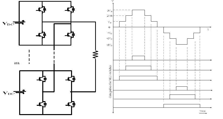 |
| Fig.2. Multi Level CHB bridge inverter and its voltage waveform |
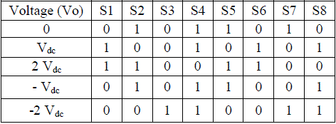
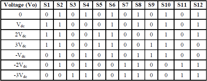
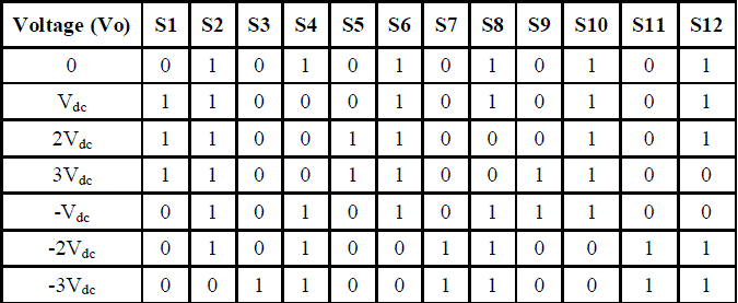
| The switching states for five level, seven level and nine level CHB inverters are shown in the following tables |
| TABLE. III SWITCHING STATES OF FIVE LEVEL CHB |
 |
| TABLE. IV SWITCHING STATES OF SEVEN LEVEL CHB |
 |
| TABLE. V SWITCHING STATES OF SEVEN LEVEL CHB |
 |
| TABLE. VI SWITCHING STATES OF NINE LEVEL CHB |
 |
| B. Carrier based PWM techniques: |
| TABLE VII COMPARISON OF ADVANCED MODULATION TECHNIQUES |
 |
| Carrier based modulation schemes [8] for multilevel inverter is generally classified into two types: |
| 1. Phase Shifted |
| 2. Level Shifted |
| In m level multi carrier modulation schemes require (m-1) triangular carrier wave forms. All having same frequency and amplitude. In phase shifted carrier wave forms are horizontally disposed. In level shifted carrier wave forms are vertically disposed |
| Most of the level shifted carrier based PWM techniques have been derived three carrier disposition categories. The phases of carrier signals rearrange to produce three main disposition techniques known as |
| 1. PD (Phase Disposition) |
| 2. POD (Phase Opposition and Disposition) |
| 3. APOD (Alternate Phase Opposition and Disposition). |
| The reference wave positioned at centre of the carrier set continuously compared with carrier waves. When reference goes above all carriers a maximum output is obtained similarly when reference goes down each carrier the corresponding levels in the inverter output gets reduced. The carrier arrangements and corresponding switching patters of five levels CHB MLI are shown in below figures |
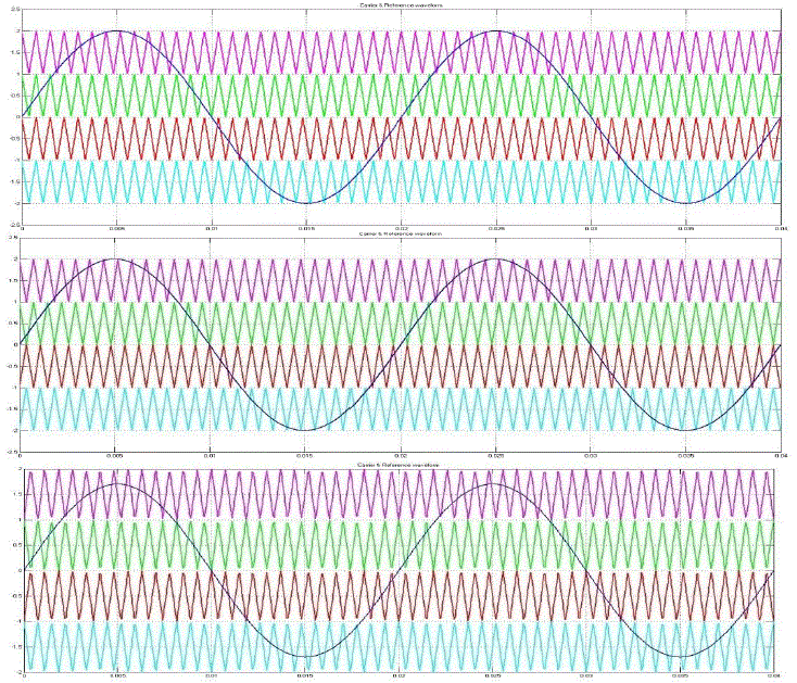 |
| Fig.3 Five Level inverter’s PD, POD, APOD carrier & reference waveforms with ma=0.85 |
SIMULATION
|
| The simulation results for different levels of CHB MLI with PD & 13th level with PD, POD, APOD are shown below: |
 |
| Fig. 4 Voltage and FFT analysis of 3 level PD CHB MLI |
 |
| Fig.5 Voltage and FFT analysis of 5 level PD CHB MLI |
 |
| Fig.6. Voltage and FFT analysis of 7 level PD CHB MLI |
 |
| Fig.7. Voltage and FFT analysis of 9 level PD CHB MLI |
 |
| Fig.8. Voltage and FFT analysis of 11 level PD CHB MLI |
 |
| Fig.9 Voltage and FFT analysis of 13 level PD CHB MLI |
 |
| Fig.10.Voltage and FFT analysis of 13 level POD CHB MLI |
 |
| Fig.11 Voltage and FFT analysis of 13 level APOD CHB MLI |
| TABLE VIII COMPARISON OF DIFFERENT LEVELS THD |
 |
| From all the above simulation results we can say that as the number of levels increases the output voltage wave form, which is approximated to sinusoidal wave form and THD also decreases. This is most essential in power quality improvement. PD technique has low harmonic content compared to other technique as shown below |
| TABLE IX COMPARISON OF DIFFERENT CARRIER WAVE BASED FOR DIFFERENT LEVELS OF MLI |
 |
CONCLUSION
|
| The different techniques for generating pulses for CHB MLI are shown along with THDs. All the simulations are simulated in MATLAB/SIMULINK. The PD technique is easy and found low THD compared to other techniques up to 13th level. As the levels are increasing the voltage stress also decreases for same power and voltage rating. The power losses are reduced and there by increases the power quality, efficiency and life of the system. As it is modular, it is more reliable and robust. The developed CHB is used for electric utility applications, which avoids the use of transformer and can interface the renewable energy to grid. The applications of simulated CHB can be used for inverter power supplies, industrial drives, hybrid electric vehicles, VAR and harmonic compensators like filters, etc. |
References
|
- ShwetaGautam and Rajesh Gupta “Switching frequency derivation for cascaded MLI operating in current control model using multi bandhysteresis modulation” IEEE transactions on power electronics, vol .29, no.3, pp.1480-1489, march 2013
- B.subhanandhini and V.Jegethesan “Application of hysteresis pulse width modulation for multilevel inverters,” IEEE international conferenceon advances in engineering science and management, pp.387-389, march 2012
- PradyumnChaturvedi, Shailendra Jain, and PramodAgarwal, “Carrier-Based NeutralPoint Potential Regulator WithReduced Switching Lossesfor Three-LeveDiode-Clamped Inverter,” IEEE transactions on industrial electronics, vol. 61, no. 2, pp.387-389, february 2014
- Sujitha N and Ramani K. "A new Hybrid Cascaded H-Bridge Multilevel inverter - Performance analysis," International Conference onAdvances in Engineering, Science and Management (ICAESM), pp.46-50, March 2012
- Booma N, and Sridhar N. "Nine level cascaded H-bridge multilevel DC-link inverter," International Conference on Emerging Trends inElectrical and Computer Technology, pp.315-320, March 2011
- Gobinath K, Mahendran S and Gnanambal I., "Novel cascaded H-bridge multilevel inverter with harmonics elimination," IEEE InternationalConference on Green High Performance Computing , pp.1-7, March 2013
- Nair Ravi Jidin, Auzani Othman MdNazri,JopriMohdHatta and Manap Mustafa "Comparison performance of 3-Level and 5-Level CascadedH-Bridge multilevel inverter of DTC of Induction Machine," International Conference on Electrical Machines and Systems, pp.2100-2104,Oct. 2013
- Prasad K.N.V., Kumar G.R., Kiran T.V. and Narayana G.S. "Comparison of different topologies of cascaded H-Bridge multilevel inverter,"International Conference on Computer Communication and Informatics, pp.1-6, Jan. 2013
- Azli N.A., and Choong Y. C. "Analysis on the Performance of a Three-phase Cascaded H-Bridge Multilevel Inverter," IEEE International onPower and Energy Conference, vol., no., pp.405-410, Nov. 2006
|