ISSN ONLINE(2278-8875) PRINT (2320-3765)
ISSN ONLINE(2278-8875) PRINT (2320-3765)
Prabha1, Tanujabai J.M2, S. Krupesh3
|
| Related article at Pubmed, Scholar Google |
Visit for more related articles at International Journal of Advanced Research in Electrical, Electronics and Instrumentation Engineering
The paper Real time automization of agricultural environment for social modernization of Indian agricultural system usesARM7 and GSM'and is focused on automizing the irrigation system for social welfare of Indian agricultural system. Using this system the condition of the field can be sensed with help of sensors; the related information is displayed on LCDand transmitted to former/user. The project is implemented by using advanced processor ARM7TDMI which is a 32 bitmicrocontroller, GSM serves as an important part as it is responsible for controlling the irrigation on field and sends information to the receiver through coded signals. GSM operates through SMSs and is the link between ARM processor and centralized unitsystem with microcontroller. The 16X2 LCD display is used to read the condition of the field at workstation itself.
Keywords |
| ARM Controller, GSM, Temperature sensor, Real-Time System, Data Acquisition and At Commands LPC2148,16X2 LCD display. |
INTRODUCTION |
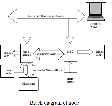
| It is a very interesting application. An integrated wired/wireless solution allows one to exploit the positive aspects of both technologies by improving performances and productivity. Various network topologies that have to be implemented depend on the requirement of the application. The entire farm can be controlled by LAN[5], implemented based on the requirement of the farm application. Each node will be connected with the sensors, solenoid valves, and ARMmicrocontroller [2]. They are connected with each other by wireless systems.The sensorsare used to monitor and collect the information about the climatic condition of the farm like temperature, humidity, day/night mode and also to check the water level with dry/wet condition of farm.For the wireless section, GSM type network has been used because it is modern wireless sensor networks. |
| While moving on to the wired section a Controller Area Network (CAN) type network has been chosen because of its simplicity, Robustness, flexibility, cheapness, and good performances. All these nodes can be connected to the control unit through wired system using CAN. |
LITERATURE SURVEY |
| Over 50 years since its independence, India has made immense progress in its agriculture system to increase food grain. Two years of severe drought in 1965 and 1966 convinced India to reform its agricultural policy. Even though agricultural policy was success, irrigation infrastructure was very poor hence Indian farmer innovated with tube-wells, to harvest ground water. New technology were adopted to irrigate the agriculture land in large. The lasting benefits of improved farming technologies depends on whether India develops infrastructure such as irrigation network, flood control systems, reliable electricity usage and production capacity. |
| As irrigation becomes the major part to have growth at economic status of our country. In time watering and proper application of bio fertilizer, along with proper monitoring of fields results in the social modernization of Indian agriculture system.This became quite interesting concept which is going to be major tool to reduce the power cost required for automization of agriculture. |
| This system uses the integration of the both wired and wireless techniques and ARM controller to have regular monitoring on the environmental conditions of farm and also provides the necessary precautions to be taken for yield to increase for modern agriculture. |
METHODOLOGY |
| The prototype model real-time automization of agricultural environment for social modernization of Indian agricultural system will be made in the following steps: |
| ïÃâ÷ Complete layout of the whole setup willbe drawn inform of a block diagram for each node. |
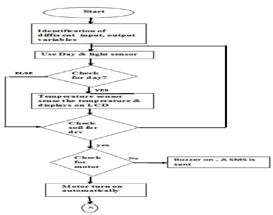
| ïÃâ÷ Day and night sensor will first sense the condition and give its output to the microcontroller & is displayed on the LCD. |
| ïÃâ÷ The temperature sensed by sensor is displayed on LCD |
| ïÃâ÷ The soil condition is checked by moisture sensor, depending upon the soil condition & water level, water pump motor is turned on or off. |
| ïÃâ÷ The motor thefting can be prevented by ARM controller by informing the farmer by sending SMS & buzzer alarm. |
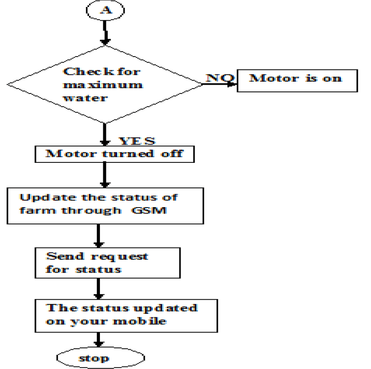
| ïÃâ÷ The status of the whole farm can be checked & updated wirelessly with help of GSM technology. |
BLOCKDIAGRAM |
| CAN and LAN network |
| The below block explains about CAN and LAN network used for connecting multiple Nodes created with ARM controller to monitor multiple farms with a single network. |
 |
 |
FLOWCHART |
 |
` |
HARDWARE DESCRIPTION |
| 1. Sensors: Temperature sensors are devices used to measure the temperature of a medium.There are two kinds of temperature sensors contact sensors and non-contact sensors. However, the three main types are thermometers, resistance temperature detectors and thermocouples. All three of these sensors measure a physical property (i.e.volumeofaliquid,currentthroughawire),which changes as a function of temperature. |
| 2.HumiditySensor:This sensor checks the presence of water in air.The amount ofwater vapor in air can affect the plants growth. The presence of water vaporal so influences various physical,chemical,andbiological processes. |
| 3.Day and Night Sensor:A photo resistor or light dependent resistor(LDR) is are sistor whose resistance decreases with increasing incident light intensity; in other words, it exhibits photoconductivity. A photoresistor is made of a high resistancese miconductor. High frequency, photons absorbed by the semi-conductor give bound electronse noughenergy to jump into the conduction band. The resulting free electron (anditsholepartner) conduct electricity, there by lowering resistance. |
| 4. ADC0808/ADC0809: It’s a 8-Bit Μp compatible A/D converters with 8-channel multiplexer. The ADC 0808, ADC 0809 data acquisition component is am on olithic CMOS device with an 8-bit analog-to-digital converter, 8-channel multiplexer and microprocessor compatible control logic. The 8-bit A/D converte uses successive approximation as the conversion technique. The converter features a high impedance chopper stabilized comparator, a 256R voltage divider with analog switch tree and a successive approximation register. The 8-channel multiplexer can directly access any of 8-single-ended analog signals. The devicee liminates the need for external zero and full-scale adjustments. Easy interfacing to microprocessors is provided by the latched and decoded multiplexer address inputs and latched TTLTRI-STATE ® outputs. |
| 5. KIA7805AP: It is a three terminal positive voltage regulator suitable for CMOS,TTL and other digital IC’s power supply. It has internal thermal overload protection and internal short circuit current limiting features. |
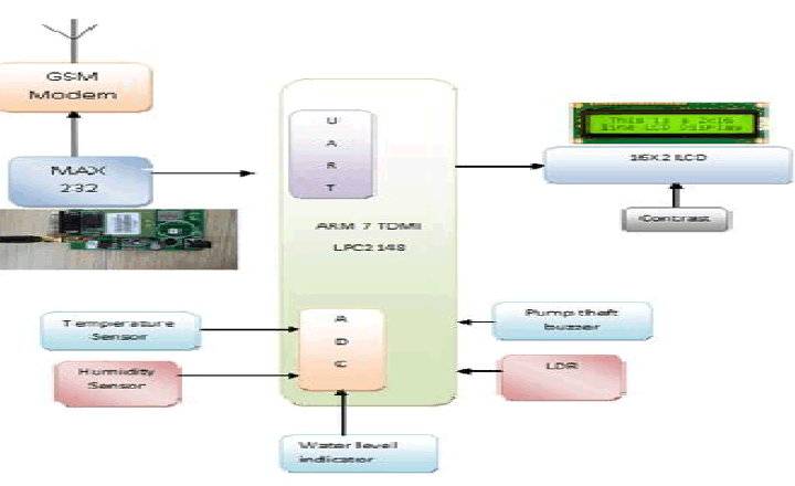
| 6. Arm controller: Arm controller(LPC2148)isusedtocontrolandinterfacetheRelays,SensorsandMotor.Thisisalowpower, high-performance controller |
| 7. GSM:A GSM modem is a wireless modem that works with a GSM wireless network. Computers use AT commands to control modems. Both GSM modems and dial-up modems support a common set of standard AT commands. So we can use a GSM modem just like a dial-up modem. |
| The main difference between them is that a dial-up modem sends and receives data through a fixed telephone line while a wireless modem sends and receives data through radio waves. GSM is one of the most vital components in our set up since all the communication between the users and centralized unit takes place through this modem. GSM communicates with ARM through I2C bus. |
| A GSM modem can be an external device or a PC Card. Typically, an external GSM modem is connected to a computer through a serial cable or a USB cable. Like a GSM mobile phone, a GSM modem requires a SIM card from a wireless carrier in order to operate. The description of GSM is given below. |
| 8.Water Level sensors: This sensor detects the level of substances thatflow including liquids, slurries, granular materials and powders. Fluids and fluidized solids flow to become essentially level in their containers (or other physical boundaries) because of gravitywhereas most bulk solids pile at an angle of repose to a peak. The substance to be measured can be inside a container or can be in its natural form (e.g., a river or a lake). The level measurement can be either continuous or point values. Continuous level sensors measure level within a specified range and determine the exact amount of substance in a certain place, while point-level sensors only indicate whether the substance is above or below the sensing point. Generally the latter detect levelsthat are excessively high or low. |
| 9. Motor pump theft detector: This sensor checks the presence of the motor and if motor is absent then ARM activates the buzzer alarm and sends SMS to the farmer’s mobile. |
IMPLEMENTATION |
SOFTWARE USED: |
| WINDOWS XP: This is an Operating System (OS) on which all the software applications required for our project are going to be run. |
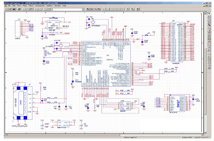
| OrCAD:OrCAD is a proprietary software tool suite used primarily for electronic design automation. The software is used mainly to create electronic prints for manufacturing of printed circuit boards, by electronic design engineers and electronic technicians to manufacture electronic schematics. |
| OrCAD Capture CIS is a software tool used for circuit schematic capture. It is part of the Or CAD circuit design suite.Capture CIS is nearly identical to the similar OrCAD tool, Capture. The difference between the two tools comes in the addition of the component information system (CIS). The CIS links component information, such as printed circuit board package footprint data or simulation behavior data, with the circuit symbol in the schematic. When exported to other tools in the OrCAD design suite, the data stored in the CIS is also transferred to the other tool. Thus, when a design engineer exports a schematic to the circuit board layout utility, the majority of the circuit elements have footprints linked to them. This saves time for the design engineer. |
| Keil Micro vision 3 IDE:The system was designed in Embedded C and implemented in KEIL μVision IDE, The μVision IDE from Keil combines project management, make facilities, source code editing, program debugging, and complete simulation in onepowerful environment. The μVision development platform is easy-to-use and helping you quickly create embedded programs that work. The μVision editor and debugger are integrated in a single application that provides a seamless embedded project development environment. |
| Software Development Cycle |
| When you use the Keil μVision3, the project development cycle is roughly the same as it is for any other software development project. |
| 1. Create a project, select the target chip from the device database, and configure the tool settings. |
| 2. Create source files in C or assembly. |
| 3. Build your application with the project manager. |
| 4. Correct errors in source files. |
| 5. Test the linked application. |
| The following block diagram illustrates the complete μVision3/ARM software development cycle. Each component is described below |
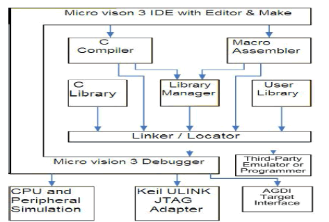 |
| In the μVision3 Debug Mode you verify your program either with a powerful CPU and peripheral simulator or with the Keil ULINK USB-JTAG Adapter (or other AGDI drivers) that connect the debugger to the target system. The ULINK allows you also to download your application into Flash ROM of your target system. |
 |
Flash Magic Software: |
| How to Download Hex File into MCU of Board |
| The method to download Hex File into Flash Memory of MCU in Board is to use Program Flash Magic that is connected with MCU through Serial Port of computer PC. This program can be downloaded free without any charge |
Proceeding to Download Hex File into MCU |
| 1. Interface RS232 Cable between RS232 Serial Port of PC and Board UART-0 (CN3). |
| 2. Supply power into board; in this case, we can see red LED1 is in status ON. |
| 3. Set jumper BR4 (INT1) in ON state. |
| 4. Run Program Flash Magic, it will display result as shown in Figure 1.1 |
| 5. Start setting the initial values into program as desired, so we configure values into program as follows; |
| Select COM port corresponding with (in this example, it is COM1) |
| Set the baud rate to 9600 |
| Set Device to be LPC2148 |
| Set Interface to be None ISP |
| Set Crystal Oscillator with MHz corresponding with the value internal Board. In this case, it is 12.000MHz, so we must set to be 12. |
| Press ISP LOAD Switch (S1) and RESET Switch (S2) on Board “ARM7 LPC2148 Development Board” to reset MCU to run in Boot Loader following the processes; |
| Press ISP LOAD Switch (S1) and hold |
| Press RESET Switch (S2) while ISP LOAD Switch (S1) is being held. |
| Remove RESET Switch (S2) but ISP LOAD Switch (S1) is being held. |
| Lastly, remove ISP LOAD Switch (S1). |
| 6. Select format of erasing data to be “Erase all Flash + Code Rd Prot”. |
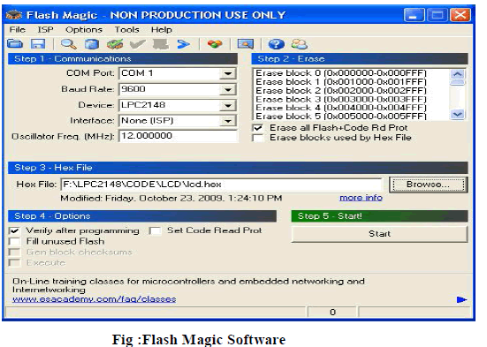 |
| 7. Set Option to be “Verify after programming”. |
| 8. Click “Browse” to select HEX File for downloading. |
| 9. Click “Start”, Program Flash Magic will start downloading data into MCU instantly. In this case, we can see the status operation at Status Bar and we must wait for the operation until it is completed. |
| 10. When the operation of program is complete, press RESET Switch (S2) on Board and MCU will start running follow the downloaded program instantly. |
RESULTS |
| After the feasible results obtained for monitoring and controlling of farm which is displayed in LCD display and. A hardware kit has been developed and put it on the farm environment. The kit consists of a power supply unit, various sensors, and the Arm controller unit. The output from the sensors is continuously given to the Arm.The feasible results obtained for monitoring and controlling of farm which is displayed in LCD display. In the real application the entire kit it is fixed on the farm. When the parameters like temperature, humidity, soil wetness and other conditions such as if soil is dry then automatically motor turns on and checks for water level reached at farms. If it is at maximum level then ARM automatically turns off motor to pump water, which is continuously monitored and controlled by ARM controller. |
 |
SOFTWARE RESULTS |
ALGORITHEMS: |
| Algorithm for automation is as follows. |
| 1. Start |
| 2. Initialize ADC, LCD, UART |
| 3. Get all set points from EEPROM. |
| 4. Get the feedback from LDR. |
| 5. If it is day, then checks for temperature sensor. |
| 6. Get feedback from Temperature sensor and display on LCD. |
| 7. Get the feedback from moisture sensor. |
| 8. If soil is dry? Then ARM checks for motor presence. |
| 9. If motor is present then motor turns ON automatically. |
| 10. If motor is not present, then ARM activates the buzzer alarm and sends SMS to farmer’s Mobile. |
| 11. Get the feedback from the water level sensor. |
| 12. If water reaches maximum set level, then motor turns OFF automatically. |
| 13. If soil is wet, then motor remains off. |
| 14. Monitored status is updated to GSM and Get the request interrupt from GSM. |
| 15. The newly updated status of the farm is sent to user mobile. |
| 16. Stop. |
ADVANTAGES |
| 1. Ease of maintenance. |
| 2. Accessing the data from any remote place. |
| 3. Less power consumption. |
| 4. Very faster communication. |
CONCULSION |
| After carrying out the proposed work, the investigator expects the following outcomes: |
| Development of Real-Time automization of agricultural environment for social modernization of Indian agricultural system with various parameters being controlled by a microcontroller and maintained further to an optimum value required for adequate growth of plant, using the low power by adaption of both wired and wireless technology. The status of the farm is monitored with the help of different sensors and data is stored at EEPROM, depending on the requirement of the farm the adequate facilities of water level is chosen by the controller and hence the yield of the farm can be increased. |
| The proposed system is very use full for regular monitoring of farm status without visiting manually, and saves time and also use full to monitor hilly areas and remote areas, which were hard to visit manually. |
| The system not only saves the energy consumption significantly, but also reduces a large number of inputting on the human and material resources in the management. Applying embedded technology and ZigBee wireless transceiver technology to the rapid deployment system of the incident detection of emergency food storage environment without complicated connections, it enhances the system’s flexibility, small size, low cost and good effective, so it is easy to install and migrate. |
References |
|