ISSN ONLINE(2278-8875) PRINT (2320-3765)
ISSN ONLINE(2278-8875) PRINT (2320-3765)
Mr.S.A.Elankurisil1, J. Baskaran2, K.Ashokkumar3
|
| Related article at Pubmed, Scholar Google |
Visit for more related articles at International Journal of Advanced Research in Electrical, Electronics and Instrumentation Engineering
A forward mode low voltage (24V) is converted high voltage (400V) by using boost mode this obtain by using for switches alone. Buck switches are not provide with any pulses are not provide with any pulse the result boost mode converter with R load and motor load are presented. The motor is run successfully. The reverse mode in this mode high voltage is converted low voltage by using buck mode switches. In the reverse mode pulse are a given only buck switches and pulse not gives boost switches.
Keywords |
| DC-DC converter, Buck mode, Boost mode, Matlab |
INTRODUCTION |
| A bidirectional converters are used DC of one level to DC Of another level they can be used it is required for the power to flow in both the directions if the machine with the battery operates the car works as motor power followed from the grid to the load. If the car goes down the hill the power flows from the generated to the grid .the mode is forward mode the generator is reverse mode. |
| A bidirectional DC–DC converter with coupled inductor is proposed. Renewable energy systems are more and more widely used in the world such as solar and wind energy. However, photovoltaic (PV) solar or wind power cannot provide sufficient power when the load is suddenly increased. The battery with bidirectional DC–DC converter is needed [1]-[3]. Conventionally, the batteries are series strings used to provide a high voltage (HV). However, temperature differences or little mismatches cause charge imbalance, which might shorten the life of batteries. Although the batteries operated in parallel strings alleviate the problems, the output voltage remains low by this connection way. Therefore, a high-efficiency bidirectional DC–DC converter with a high convention ratio is a key component of battery applications.Isolated bidirectional DC–DC converters such as half and full-bridge types [10],[11] can provide high step-up and step-down voltage gains by adjusting the turn ratio of the transformer. The high step-up gain and the high step-down voltage gain can be achieved. The number of switches is usually between four and eight. Also, some isolated bidirectional converters are characterized by a current fed rectifier on the low- voltage (LV) side and a voltage-fed rectifier on the high voltage (HV) side.[12],[13] |
OPERATING PRINICPLES OF BIDIRECTIONAL DC-DC CONVERTER |
| The Bidirectional DC–DC Converter With Coupled Inductor is a forward mode a 24V is boosted to 48V by using forward boost mode, this obtained by using the purpose for boost switch alone .buck switch are not provided with any pulse .the result boost mode converter with R load and motor are presented. the motor is are successfully .Reverse mode in this mode 48V DC is converted into 24V DC by using buck mode switches in their reverse mode pulses are only buck switches and pulse do not gives boost switches . The bidirectional converter can have high stepdown gain. Aside from that, all of the switches achieve zero voltage-switching turn-on, and the switching loss can be improved. Due to two active clamp circuits, the energy of the leakage inductor of the coupled inductor is recycled. The efficiency can be further improved. |
BIDIRECTIONAL DC–DC CONVERTER WITH COUPLED INDUCTOR |
| Renewable energy systems are more and more widely used in the world such as solar and wind energy. However, photovoltaic (PV) solar or wind power cannot provide sufficient power when the load is suddenly increased. Thus, the battery with bidirectional DC–DC converter is needed. Conventionally, the batteries are series strings used to provide a high voltage (HV). However, temperature differences or little mismatches cause charge imbalance, which might shorten the life of batteries. Although the batteries operated in parallel strings alleviate the problems, the output voltage remains low by this connection way. A high-efficiency bidirectional DC–DC converter with a high convention ratio is a key component of battery applications. |
| Isolated bidirectional DC–DC converters such as half and full-bridge types can provide high step-up and step-down voltage gains by adjusting the turn ratio of the transformer. The high step-up gain and the high step-down voltage gain can be achieved. The number of switches is usually between four and eight. Also, some isolated bidirectional converters are characterized by a current-fed rectifier on the low voltage (LV) side and a voltage-fed rectifier on the HV side. |
| The leakage inductor of the transformer leads to the HV spike on the main switch during switching transition. Thus, the isolated bidirectional full-bridge dc–dc converter with a fly back snubber circuit is proposed. A novel soft commutating isolated boost full-bridge zero-voltage-switching (ZVS) pulse width-modulation DC–DC converter is proposed. The energy of the leakage inductor is recycled and not dissipated. However, the number of switches is also added. Aside from that, the bidirectional converter based on fly back or forward converters are proposed. The leakage inductor of the transformer also causes HV spike on switches. Thus, an active clamp circuit is applied in the bidirectional converter, which is proposed. |
| For nonisolated applications, nonisolated bidirectional converters, which include the conventional boost/buck type, the soft-switching technique on conventional boost/buck converter, three levels, multilevel, SEPIC/Zeta, switchedcapacitor bidirectional converter and a coupled-inductor-type bidirectional converter, is proposed where using two auxiliary switches, i.e., ZVS, is provided . For some ZVS purpose, the authors have improved the coupled inductor bidirectional topology with only one auxiliary switch. The authors have modified the two previous converters and proposed a converter without any auxiliary switches. |
| To achieve a high conversion ratio, two inductors charged in parallel and discharged in series are proposed. In the aforementioned converters, the multilevel type is a magneticless converter and the conversion ratio based on stack of capacitors, which need 12 switches in this converter. If higher step-up and step-down voltage gains are required, more switches are needed. The coupled-inductor converters easily achieve a high conversion gain. However, the energy leakage energy needs to be recycled. |
| Based on the previous research of the high step-up converter a high-efficiency, high-conversion-ratio, and clampmode bidirectional converter isproposed. The initial high step-up converter adds two pairs of additional capacitors and switches on the secondary side of the coupled inductor to achieve an HV ratio. The secondary side of the coupled inductortwo capacitors in parallel and discharge in series when the switch is on and off. Thus, the high output voltage is build by replacing the diodes with switches. The high step down can be also achieved because two capacitors are charged in series and discharged in parallel. It is opposite to the step up concept. Apart from this, two capacitors are like two pairs of active clamp circuits. Switches are ZVS turned on. The switching loss can be improved. The bidirectional converter has the higher conversion ratio than other high step-up and step-down converters. Compared with the proposed topology has higher conversion ratio. There are some common points in conventional bidirectional converters with a coupled inductor; the leakage inductor problem is needed to be solved by active clamp, passive clamp, or auxiliary circuit. The circuit is that the secondary side is based on the voltage doublers to add the voltage gain. If the diodes used a synchronous rectifier,the bidirectional functions can be achieved. The energy of the leakage inductor can be recycled by capacitors of the voltage doublers and make all switches ZVS. The circuit did not use other auxiliary circuits. The method and concept can be alsoused in many high step-up DC–DC converters |
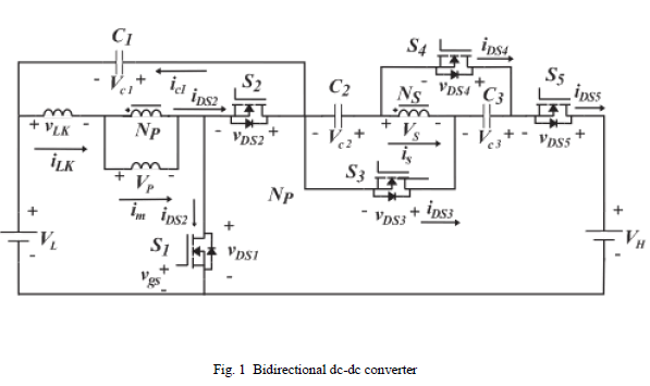 |
| The bidirectional dc-dc converter is both side working is forward mode and reverse mode .The output side is load connected in boost and buck mode are connected. |
BIDIRECTIONAL DC-DC CONVERTER WITHΠ FILTER |
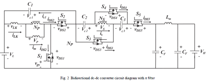 |
| In proposed converter is π is added the output side .this filter is helps reduced in the ripple voltage in the output side. I f the ripple voltage is reduced the losses in dc machines are reduced and the efficiency is improved. If the current ripple is reduced. The sparking is reduced .thus the proposed system is better than existing system. |
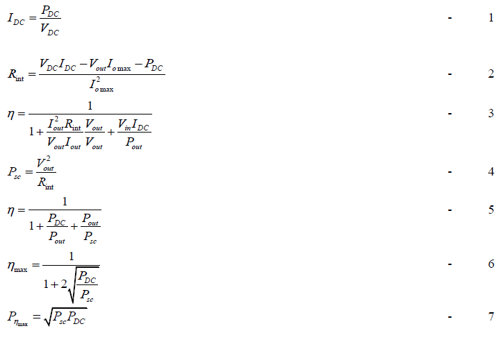
| The peak to peak ripple voltage is 0.02 to 0.01 is reduced. The following formulae to find the efficiency of the DC-DC converter. |
 |
SIMULATION RESULTS: |
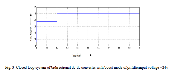
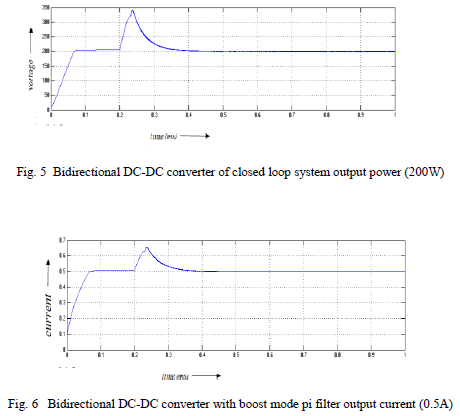
| A. BOOST MODE CLOSED LOOP SYSTEM |
 |
 |
 |
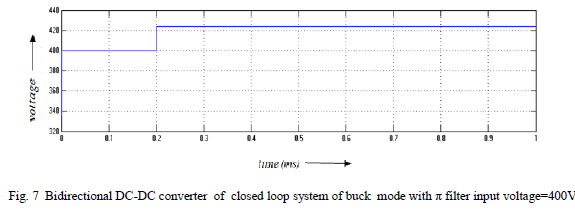
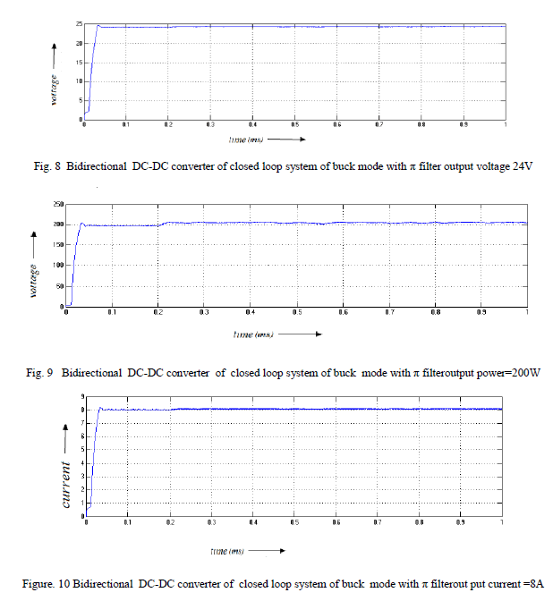
| B. BUCK MODE CLOSED LOOP SYSTEM: |
 |
 |
 |
 |
CONCLUSION |
| The ripple voltage are reduced by using π filter.the steady state error is reduced by using closed loop system.The Simulink model are developed for closed loop system buck mode and boost mode a novel, highefficiency, high step-up/step-down bidirectional dc–dc converter. By using the capacitor charged in parallel and discharged in series by the coupled inductor, high conversion ratio and high efficiency have been achieved. The steady-state analyses of the proposed converter have been discussed in detail. The voltage gain and the utility rate of the magnetic core have been increased by using a coupled inductor with a low turn ratio. The energy of the leakage inductor has been recycled with the clamp circuit. The Bidirectional DC–DC converter with coupled Inductor Simulation results are obtained, showing a good agreement with the analysis |
References |
|