International Journal of Advanced Research in Electrical, Electronics and Instrumentation Engineering
ISSN ONLINE(2278-8875) PRINT (2320-3765)
ISSN ONLINE(2278-8875) PRINT (2320-3765)
Himanshu Doraya1, Richa Parmar2, Mal Chand sharma3, Bipul Kumar4,
|
| Related article at Pubmed, Scholar Google |
Visit for more related articles at International Journal of Advanced Research in Electrical, Electronics and Instrumentation Engineering
This Paper shows a technique named as Space Vector Pulsed Width Modulation and describes that total harmonic distortion can be reduced considerably using this technique. In this paper MATLAB/Simulink model has been designed and result is discussed.
Keywords |
| SVPWM, Inverter |
INTRODUCTION |
| In Power System applications one major problem in output is distortion. For mitigation of this different methodologies have been used. With advances in Solid-State Power Electronics Devices, various Pulse Width Modulation (PWM) techniques have been developed for Industrial applications. Shao-Liang An, Xiang-Dong Sun, Member, IEEE, Qi Zhang, Yan-Ru Zhong, and Bi-Ying Ren has been studied SVPWM Technique and this paper shows further study and talk about reduction of total harmonic distortion. PWM is a means of transmitting information in a series of pulses, where the data being transmitted is encoded in the width of the transmitted pulse. In the Space Vector Pulse Width Modulation technique, the duty cycles are computed rather than derived through comparison as in Sine Pulse Width Modulation. The SVPWM technique can improve the fundamental component by up to 27.39% than SPWM. This paper discusses the studies of Space Vector PWM technique (SVPWM). The simulation results show that the SVPWM technique has lower total harmonic distortion than the PWM technique. |
SVPWM TECHNIQUE |
| In the Space Vector Pulse Width Modulation(SVPWM) technique, the duty cycles are computed rather than derived through comparison as in Sine Pulse Width Modulation. The main concept behind Space Vector Pulse Width Modulation is to divide the two Dimension-plane into six equal areas which is called sector. |
 |
| Each sector is determined by four vectors Vi,Vi+1 where i ∈ {1-5} these vectors are called active vectors because when these vectors are applied to the power module output voltage of the power module, will be greater than zero i.e. one of the switches Sa , Sb , Sc will not be off. |
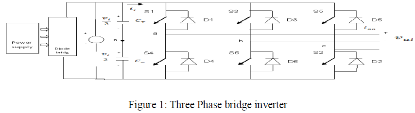
| The other two vectors V0 and V7 are called inactive vector, because all switches will be off or on. The basic principle of SVPWM is based on the eight switch combinations of a three phase inverter. The switch combinations can be represented as binary codes that correspond to the top switches S1, S3 and S5 of the inverter as shown in fig. Each switching circuit generates three independent pole voltages |
| The three phase inverter is therefore controlled by six switches and eight inverter configurations. The eight inverter states can be transformed into eight corresponding space vectors. In each configuration the vector identification uses a ‘0’ to represent the negative phase voltage level and a ‘1’ to represent the positive phase voltage level. The relationship between the space vector and the corresponding switching states is shown in figure. In addition, the switches in one inverter branch are in controlled in a complementary fashion (1 if the switch is on and 0 if it is off). [3][4] |
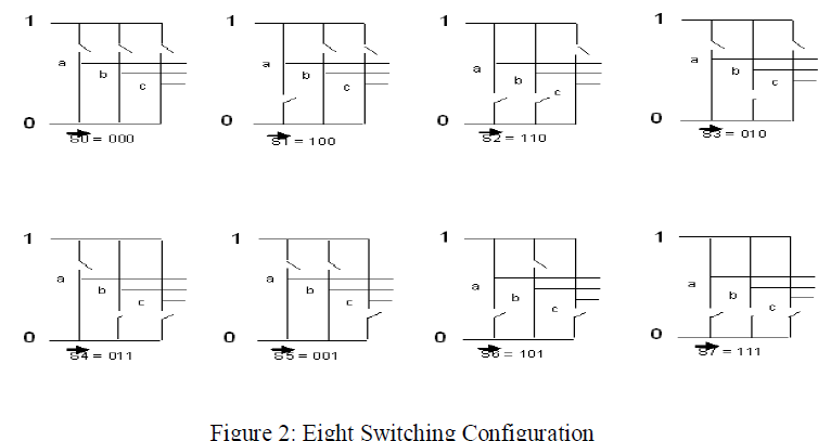 |
| Here orthogonal coordinates used to represent the three phase two level in the phase diagram.There are eight possible inverter states that can generate eight space vectors. These are given by the complex vector expressions.[5] |
SIMULATION |
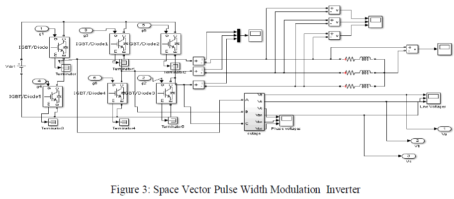
| 3.1 Simulink Model of Space Vector PWM Inverter: In the figure 3 Simulink model of SVPWM Inverter has been shown. Model has been drawn on MATLAB.[6] In the next stage output of waveforms has also been shown. |
 |
3.2 Sector Implementation |
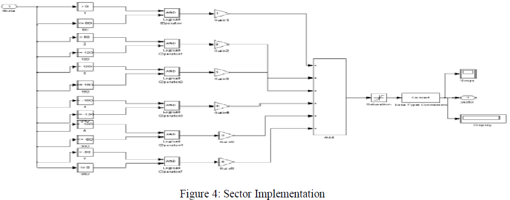
| In Figure 4 Sector Implementation has been shown. As it can be seen that there is six sectors are formed . |
 |
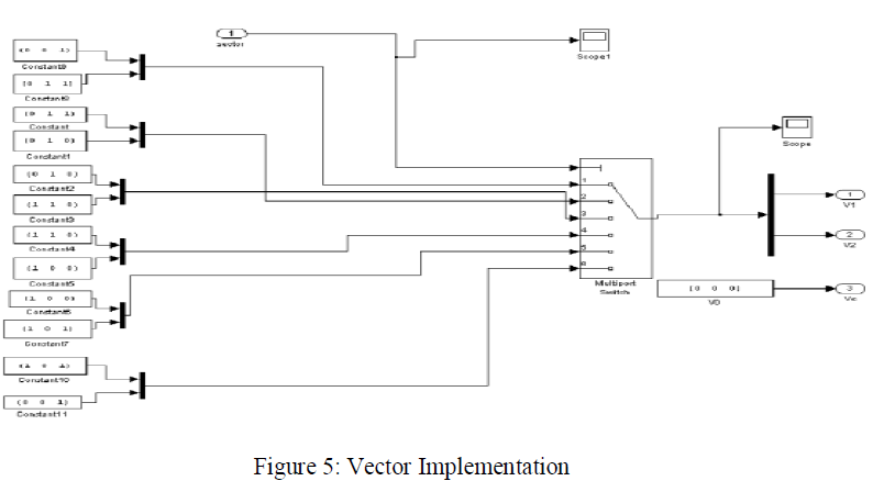
3.3 Vector Implementation |
| In figure 5 Vector implementation is shown and output can be visualize on scope. Results of this is shown in section IV. This a model of Vector Implementation using MATLAB and output can be Visualized using Scope. |
 |
RESULT ANALYSIS |
4.1 Simulation Results of Current of Space Vector Pulse Width Modulation Inverter |
| Output waveform of 3 phase sine wave is shown in figure 6. amplitude of waveform is .45. Whether frequency is kept 50 Hertz.On the x axis Time Period is shown from 0 to 0.2 Sec. on Y axis amplitude of Sine wave is shown. |
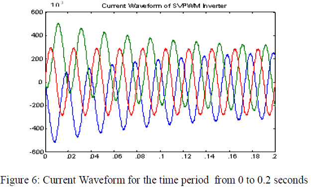 |
| Figure 6: Current Waveform for the time period from 0 to 0.2 seconds |
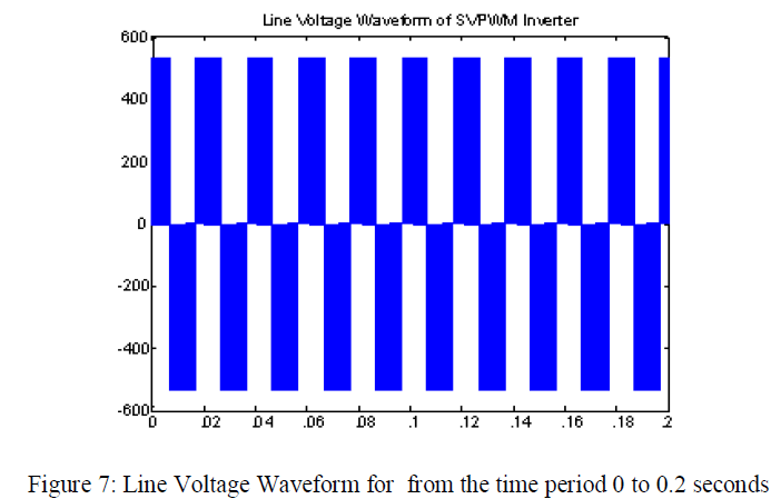
4.2 Simulation Results of Line Voltage of Space Vector Pulse Width Modulation Inverter: |
| In the Figure 4.13 waveform of Line Voltage Vao, Vbo, Vco is Shown . It is also shown in figure that Peak to Peak Voltage is 450 volt and it is shown on the Y axis and x axis represent the time period from 0 to .2 seconds. |
 |
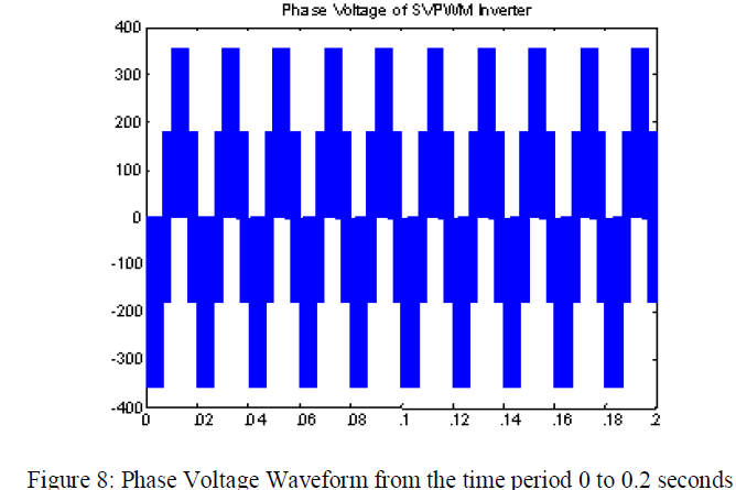
4.3 Simulation Results of Phase Voltage of Space Vector Pulse Width Modulation Inverter: |
| In the figure 4.14 phase voltage waveform of 3 phase inverter has been shown. On the x axis time period is shown from 0 to 0.2 seconds whether on y axis phase voltage is shown 350 volts. |
 |
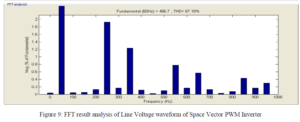
4.4 FFT Result (Analysis) of Line Voltage of Space Vector PWM Inverter |
| In the figure 4.17 FFT analysis of Line Voltage of SVPWM inverter is shown from the analysis it is clear that total Harmonic distortion is 67.18. |
 |
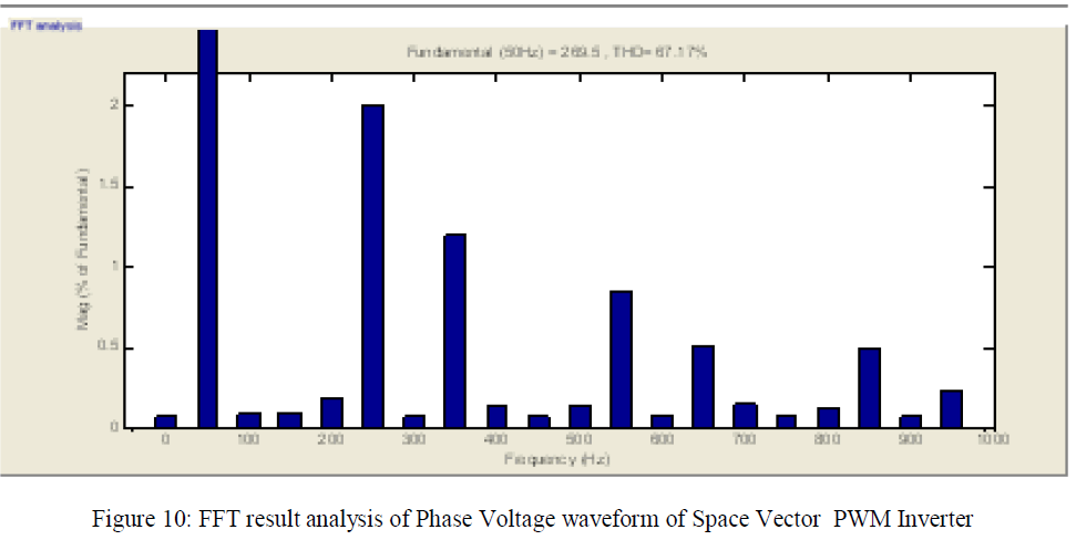
4.5 FFT Result (Analysis) of Phase Voltage of Space Vector PWM Inverter |
| In the figure 4.19 FFT analysis of Phase Voltage of SVPWM inverter is shown from the analysis it is clear that total Harmonic distortion is 67.17. |
 |
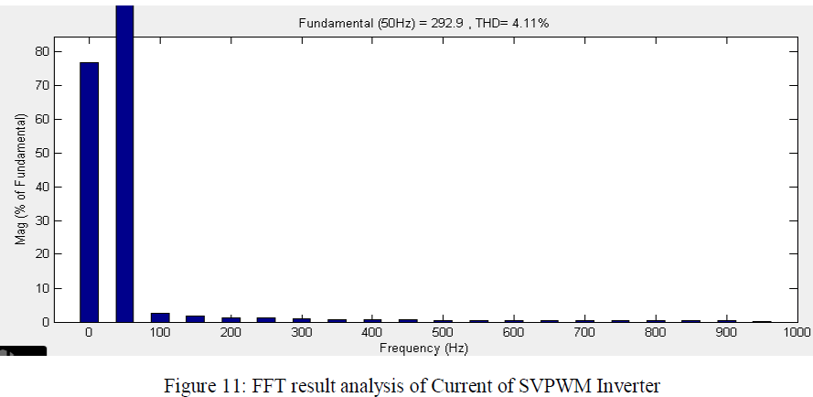
4.6 FFT Result (Analysis) of Current of Space Vector PWM Inverter |
| In the figure 4.21 FFT analysis of Current of SVPWM inverter is shown from the analysis it is clear that total Harmonic distortion is 4.11. |
 |
CONCLUSION |
| In this Paper simulation studies have been carried to show the results of SVPWM based Inverter. This Paper describes the step by step development of SVPWM based inverter mathematical model. Firstly model of SVPWM has been prepared and after that total Harmonic distortion is found using FFT analysis.In figure various voltage and current waveform has also been included . Here Space Vector Pulse Width Modulation Technique used in this paper to improve the performance of Power System equipments. Hence Simulation study results indicate that harmonics is reduced in SVPWM model. |
References |
|