ISSN ONLINE(2320-9801) PRINT (2320-9798)
ISSN ONLINE(2320-9801) PRINT (2320-9798)
Chiranjit Ghosh1, Quazi Md. Alfred2, Biswajit Ghosh3
|
| Related article at Pubmed, Scholar Google |
Visit for more related articles at International Journal of Innovative Research in Computer and Communication Engineering
The spectral response of the uniform FBG with different grating parameters such as grating length and index change are provided and discussed. The coupled mode theory is a suitable tool for analysis and obtaining quantitative information about the spectrum of a fiber Bragg grating. The coupled mode equations can be obtained and simplified by using the weak waveguide approximation. The spectrum characteristics can be obtained by solving these coupled mode equations. In this paper simulation of FBG has been carried out to analyze the spectral characteristics of the FBG. An optical FBG is being simulated with the help of advanced software module such as the R soft and the modeled sensor is evaluated for the grating and different efficiency of various grating shape parameters, modulation depth,etc. The relationship between the maximum reflectance, 3dB bandwidth and centre wavelength with grating parameters are also given and discussed. Optimization and improvement of the system can be realized by using the simulation results. Since the present work not only deals with theoretical aspects of FBGs but also leads to the development of simulation tools which can be used in the area of communications and sensors.
Keywords |
| Fiber Bragg grating, sensor, Bandwidth, Reflectivity, Simulation |
INTRODUCTION |
| The fiber Bragg grating (FBG) is an optical device with a periodic variation of the refractive index along the propagation direction in the core of the fiber[1],[2]. The principal property of FBGs is that they reflect light in a narrow bandwidth that is centered about the Bragg wavelength λB . There are various structure of FBG like uniform, apodized, chirped, tilted and long period. When light propagate through the FBG in narrow range of wavelength, the total reflection take place at Bragg wavelength and other wavelength are not affected by the Bragg grating except some side lobes exist in reflection spectrum. These side lobes can be suppressed using apodization technique. The reflection bandwidth depend on length and strength of refractive index modulation. The reflection of wavelength also depend on the temperature and strain. FBGs are simple intrinsic devices that are made in the fiber core by imaging an interference pattern through the side of the fiber[3]. FBGs can be fabricated by the exposing the fiber core to UV radiation. This induces the changes of refractive index along the core of the fiber. The resulting refractive index changes depend on the UV light exposure and exposure pattern. Several techniques are commonly used to fabricate FBGs: the point-by-point technique, the interferometric technique and the phase mask technique[4],[5]. |
| FBGs are based on the principle of Bragg reflection. When light propagates through periodically alternating regions of higher and lower refractive index, it is partially reflected at each interface between these region. If the spacing between these regions is such that all the partial reflections addup in phase when the round trip of the light between two reflections is an integral number of wavelengths, the total reflection can grow nearly 100%, even if the individual reflections are very small. Of course, that condition will hold only for specific wavelengths. For all other wavelengths, the out of phase reflections end up cancelling each other, resulting in high transmission. The condition for high reflection is known as Bragg condition. FBG consists of a periodic modulation of the index of refraction along the core of an optical fiber[6],[7]. FBG sensors are based on the fact that the Bragg wavelength changes with change in the pitch of the grating and the change in the refractive index. Thus any physical parameter (like temperature, stress, strain) which causes change in the above mentioned parameters can be sensed using a FBG by measuring the shift in the Bragg wavelength or the change in reflection coefficient of a particular wavelength[8],[9]. Refractive index of an optical fiber can vary with changes in temperature and therefore the spectral response of FBGs is also temperature dependent[10]. They are used as flexible and low cost inline components to manipulate any part of the optical transmission and reflection spectrum. The spatial quality of FBGs determines the performance of the FBG based optical communication devices. FBG is the key component for dispersion compensation and WDM[11]. |
II. FUNDAMENTAL THEORY OF FBG |
| The propagation of light along a waveguide can be described in terms of a set of guided electromagnetic waves called the modes of waveguide. In optical fibers the core cladding boundary conditions lead to coupling between the electric and magnetic field components[12],[13]. |
| Each mode has its specific propagation constants. If the periodic perturbation is introduced alongside the fiber the mode will exchange its power. This phenomenon is known as mode coupling. FBGs can be broadly classified into two types: |
| ïÃâ÷ Bragg gratings (also called reflection and short period gratings). In which coupling occurs between modes travelling to opposite directions; and |
| ïÃâ÷ Transmission gratings (also called long period gratings), in which the coupling is between modes travelling in the same direction. |
| A fiber grating is simply an optical diffraction grating, and thus its effect upon a light wave incident on the grating at an angle can be described by the familiar grating equation. |
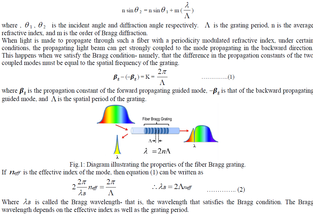 |
| Equation (2) gives us the wavelength that will undergo a strong reflection. Physically this can be understood from the fact that , at each change in refractive index, some light is reflected. If the reflections from points that are a spatial period apart are in phase, then the various multiple reflections add in phase leading to a strong reflection. This happens when we satisfy eqn(2). Using a coupled mode theory for contradirectional coupling due to a periodic perturbation, one can show that the reflection coefficient is given by |
| R=tanh2kL |
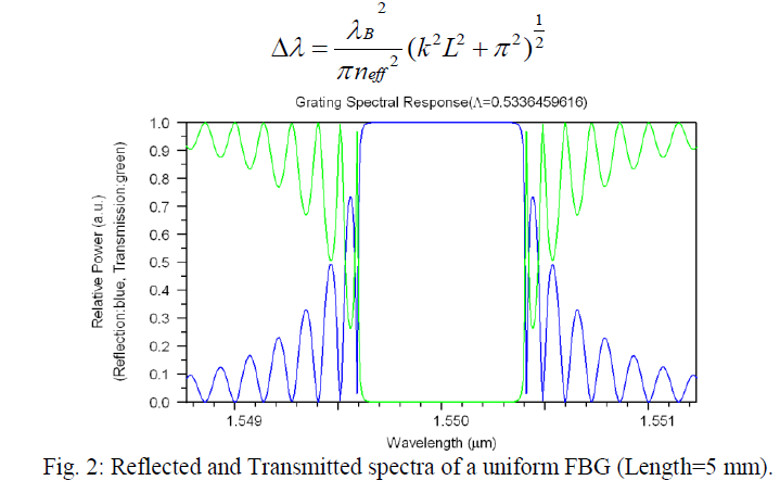
| where L is the length of the fiber grating, k is the coupling coefficient. The bandwidth of the reflection spectrum, which in this case is defined as the wavelength spacing between two reflection minima on either side of the central peak, is approximately given by |
 |
III. APPLICATION OF THE SIMULATION PROGRAM |
| A computer simulation program is a very important tool[14],[15] in the optical fiber research field. The use of expensive and delicate manufacturing systems and instrumentation can be avoided until the design is optimized. We can use the computer aided design and simulation to study fiber optical problems. The theoretical results can be obtained by using the simulation program. The factor that affects the system can be found by studying the differences between the theoretical values and the experimental results. Optimization and improvement of the system can be realized by using the simulation results. The simulation program can be used to analyze the spectral characteristics of fiber Bragg grating[16]. Uniform, Bragg gratings have been simulated by this program. The reflection and transmission spectra, group time delay and dispersion can be obtained. The value of the maximum reflectivity, sidelope reflectivity, full width at half maximum (FWHM) can be obtained too. The relationship between the grating’s variables (e.g. coupling coefficient, length of grating, chirped values) and the output spectrum values (e.g. the maximum reflectivity, bandwidth and centre wavelength) can be calculated by this program. |
A. Simulation of Uniform Fiber Bragg Grating |
| In this paper an optical FBG sensor model is being simulated with the help of advanced software modules such as the R- soft and the modeled sensor is evaluated for grating efficiency. We have chosen the following parameters for the construction of FBG model. Single mode step index optical fiber of core diameter 5.25 μm was chosen. Index of the core was fixed as 1.458 and index difference 0.0008. The simulations are to demonstrate how the spectral response of a grating is affected as the length of the grating and modulation depth (Refractive index change) altered. The reflectivity as well as bandwidth of FBG sensors changes under different grating length and modulation depth. The reflectivity increases with the increase of grating length where as Bandwidth decreases with the increasing of grating length. The reflectivity and bandwidth increases with the increase of Mod depth for a fixed grating length. The simulation results has been given in the Table 1. |
B. Simulation Results |
 |
| We investigated the influence of the Modulation depth on the amplitude reflectance spectral and the bandwidth of the uniform FBG for different grating length. Examination of the FWHM of FBG signals is commonly used for elucidating the change of bandwidth. The reflectivity and Bandwidth increases with the increase of Mod Depth for a fixed length. Five different Grating length ( L=2,5,10,15,20mm) and six different values of Mod Depth (0.0003,0.0005,0.0008,0,0012,0.0015,0.0020)were used in the simulations. The Modulation depth affects not only the bandwidth, but the maximum reflectance in Bragg ïÃÂì too. |
RESULTS |
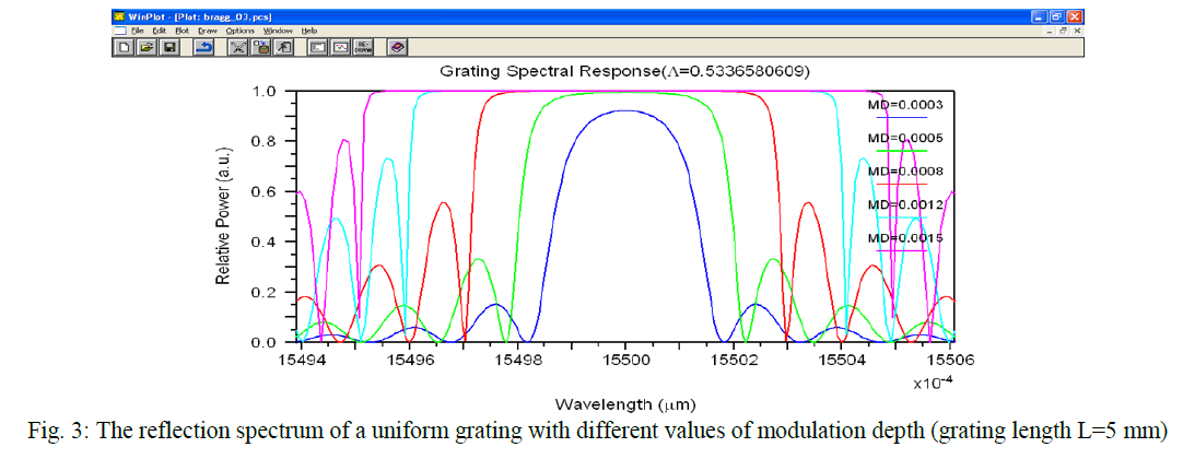 |
| The increase of Modulation depth causes the increase in Bragg r which is highly desirable for reflection FBGs. On the other hand, at the same time the bandwidth ïÃÂÃâïÃÂìBragg rises which could be harmful for WDM demultiplexers. Theoretically, FBG can be constructed with extremely small bandwidths by simply increasing the grating length. However, in practice, such devices are not easy to manufacture. Therefore the optimization is recommended for a specific application. |
 |
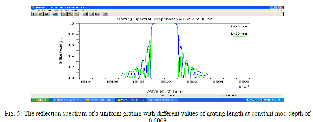 |
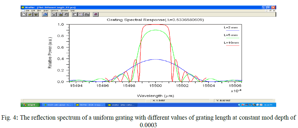
| The figure (3 ïÃâ¬Ã 5) depict the simulation results in the form of graphs of reflected power as a function of wavelength. The reflectivity and transmitted as well as the bandwidth of FBG sensors also changes if they are under different grating lengths. |
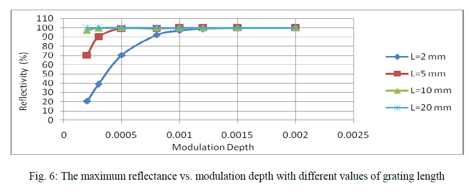 |
| The reflectivity increases with the elevation of grating length. The FBG achieved 100 % reflection when the grating length is 10 mm and maintain these values for longer wavelength. This tendency is very similar with the results of 3 dB bandwidth change but in an inverse direction where the reflectivity showed an exponential increase over the elevation of grating lengths as shown in figure (6-9). |
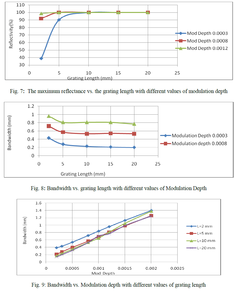 |
| From the above results upon consideration of the reflectivity elevation of the FBG sensor signals, it was confirmed that the simulated FBG sensors showed better performance as the grating length increased and achieved 100 % reflection at the grating length of 10 mm and achieved in stability for a fixed bandwidth. |
IV. CONCLUSION |
| Fiber optical component modeling is a vital step towards design of fiber optical sensors and communication system. Simulation of FBGs has been carried out to analyze the spectral characteristics of the FBG. The simulation results can be used to analyze the problems of fiber Bragg grating. Simulation software is a very rapid, efficient and economical way to design and analyze fiber optical systems. The conclusions from the study are as follows: |
| (i) The reflectivity of FBG increases with the increase in Grating Length. |
| (ii) The reflectivity increases with the increase of Modulation depth and becomes constant(100%) above Grating Length 10 mm and maintained this value for longer Grating Length. |
| (iii)100% reflection may be achieved with higher Modulation depth and lower grating length. |
| (iv)The bandwidth of the FBG sensor increases with the increase of Modulation depth. |
| From the present work optimization and improvement of the system can be realized by using simulation tools.The FBG can further be studied for long period grating as the new applications demanding further refinement and control of the grating. It is necessary to simulate these gratings as well. There should be many potential applications if simulation software could be run in the internet. Furthermore, continued work on different tuning techniques will open for an ever wider range of application areas with flexible and cost effective components. |
References |
|