International Journal of Advanced Research in Electrical, Electronics and Instrumentation Engineering
ISSN ONLINE(2278-8875) PRINT (2320-3765)
ISSN ONLINE(2278-8875) PRINT (2320-3765)
R.Srinivasan., M.E.,(Ph.D.).#1, M.Yogaselvi.,B.E.,(M.E.)*2.,Dr.R.Arulmozhiyal.,M.E.,Ph.D.#3
|
| Related article at Pubmed, Scholar Google |
Visit for more related articles at International Journal of Advanced Research in Electrical, Electronics and Instrumentation Engineering
In today’s world, due to the growing demands of technology and rise in population, there has been a tremendous pressure on the electricity demands. The world needs to find alternative sources of energy. Hence renewable sources are being considered to meet the growing demands of energy. This paper proposes a unique standalone hybrid power generation system, applying advanced power control techniques fed by four power sources are wind power, solar power, storage battery and diesel engine generator , and which is not connected to a commercial power system. Different power sources can be interconnected anywhere on the same power line, leading to flexible system expansion. A storage battery is installed within the solar power generation system, For instance, the battery is installed adjacent to the wind power generation system and a power device is used as control switch of dump load. Dump power is controlled as necessary to prevent battery overcharging. While these techniques construct a dispersed installation of different power sources, installation of dump load is necessary. Further, a high-tech dump load control method is necessary. Considerable effort was put into the development of active-reactive power and dump power controls. The result of laboratory experiments revealed that amplitudes and phases of ac output voltage were well regulated in the proposed hybrid system. It is anticipated that this hybrid power generation system, into which natural energy is incorporated, will contribute to global environmental protection on isolated islands and in rural locations without any dependence on commercial power systems.
Keywords |
| Dump load, dump power control, low cost standalone hybrid power generation system, and storage battery. |
INTRODUCTION |
| Energy and development are closely intertwined, resulting in increased use of fossil fuels, such as gas, petrol and coal which cannot be replenished or renewed. This ultimately leads to an increase in the usage of electricity. Electricity is mainly generated from non-renewable energy sources like crude oil, natural gas, coal etc. These are termed as non-renewable since they are finite and cannot match up to the needs of the world. The oil reserves of the world will not sustain in the time to come. Currently these sources are there in abundance, but will diminish in the near future because of the increasing demand of electricity. |
| Even if these sources are available in quantity, the non renewable energy sources have a big negative impact on the environment. They produce immense toxic waste and pollute the environment to a great extent. It is detrimental to plant and animal life. The usage of fossil fuels is one of the reasons for global warming. Electricity generated from fossil fuels and coals result in harmful emissions of nitrogen oxides and sulphur dioxides. These chemicals lead to acidic rivers and are lethal to mankind. All the above indicates us to discover alternate sources of energy. These alternate sources of energy are the renewable energy sources which are available in ample quantity. Renewable sources of energy mainly consist of solar energy, wind energy, biomass, geothermal and hydro power. As technology progresses, there have been efficient means to abstract electricity from the above mentioned renewable sources. |
II.EXISTING SYSTEM |
| Natural energy-based power generation systems are commonly equipped with storage batteries, to regulate output fluctuations resulting from natural energy variation. Therefore, it is necessary to prevent battery overcharging. As for the utility connected hybrid generation system consisting of a wind power, a solar power, and battery, the dump power is able to control to prevent overcharging the battery without dump load because of dump power transferred into the utility. As for the individual power generation system, it is considered that a PV system featuring low-cost and simple control, which incorporates maximum power point tracking control that makes use of diode characteristics , or a PV system that features output stability with a multiple-input dc–dc sources in combination or a cascaded dc–dc converter PV system that features good efficiency along with low cost or a wind turbine system that features output stability with a combination of an electric double-layer capacitor and storage battery is suitable for use with hybrid power generation systems to stabilize power supply. |
2.1 EXISTING SYSTEM OPERATION |
| In contrast, the standalone hybrid system is mainly composed of natural energy sources (i.e., wind power and solar power), and a storage battery; and in some cases, a diesel engine generator may be incorporated into the system as well. However, there is a tendency that the greater the system sophistication, the more suitable the power control techniques are required to be a dc–dc converter is mounted in both wind power and solar power generation systems. The two systems are interconnected at the output sides of individual converters and are also connected to the storage battery. In such a configuration, each dc–dc converter is capable of monitoring the current and voltage of the storage battery, and optimally controlling battery charging, to supply power to the load . In most cases where converters and storage batteries are set up at a centralized location, the storage batteries are commonly installed adjacent to the wind- and solar-power generation systems; therefore, there is generally no freedom to install the batteries on flat ground or in places with good vehicular access for easy maintenance and replacement. |
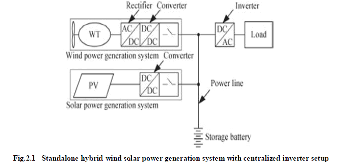 |
| In a hybrid system with a centralized inverter setup, as shown in Fig 2.1, the output of dc–dc converters is sent to an external–ac inverter to supply ac power to load. Therefore, a future increase in load will require an increase in inverter capacity. |
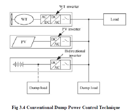
| In a system applying a dispersed inverter setup, as shown in Fig 2.2, individual wind- and solar power generation systems, each mounted with a dc–ac converter, is interconnected in parallel at the inverter output sides and are also connected to a diesel engine generator via a power line. At the same time, a dump load is also mounted on the same power line. |
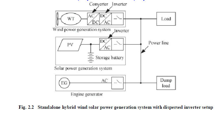 |
| In this case, a storage battery is installed within the solar power generation system, and dump power is controlled as necessary to prevent battery overcharging. Several different techniques to prevent battery overcharging are widely used. For instance, the battery is installed adjacent to the wind power generation system and a solid- state relay or power device is used as control switch of dump load. |
| Another technique is that surplus power is consumed by a hydrogen generator for a fuel battery instead of storage battery and when the hydrogen tank becomes full, dump load is applied .While these techniques construct a dispersed installation of different power sources, installation of dump load is necessary. Further, a dedicated high-speed line for battery current/voltage status data transmission, or otherwise a high-tech dump load control method, is necessary. To resolve these problems, the authors have proposed a low cost, standalone hybrid wind-solar power generation system applying advanced power control techniques. |
3.1 PROPOSED SYSTEM CONFIGURATION |
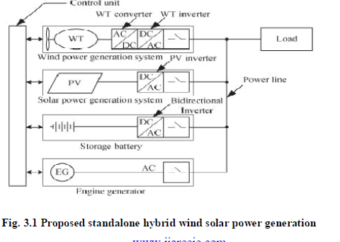
| The proposed standalone hybrid wind-solar power generation system is, as shown in Fig5.1,in outline composed off our power sources: a wind power generation system (with a WT converter and a WT inverter), solar power generation system (with a PV inverter), storage battery (with a bidirectional inverter), and engine generator (EG); and a control unit . |
| The control unit acts to send ON/OFF operation commands to individual power sources and monitor power status via a simple communication line, which is all that is needed since the data traffic volume is small. Once an ON command is sent, each power source is autonomously operated via individual inverters; however, manual setting of inverter operating conditions is also possible if required. The inverters enable redundant parallel operation, making a reliable, stable power supply possible. |
 |
3.2 SYSTEM OPERATION |
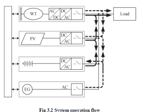
| There are number of major operation flows of the proposed hybrid system are obtained. When the remaining battery capacity is sufficient: EG operation stops, and all inverters operate in parallel. Power surplus and deficit according to the balance between the output and load can be optimally adjusted through battery charging or discharging. When the remaining battery capacity is insufficient: EG and all inverters operate in parallel. |
| When power generated by wind and solar power generation systems is insufficient to meet load demand, EG compensates for the deficiency. Concurrently, EG charges the battery via the bidirectional inverter. This inverter regulates charging power for the battery so that EG can be operated at the optimal load factor congruent with high efficiency, following a command from the control unit. |
 |
3.3 SYSTEM POWER CONTROL TECHNIQUES |
| In the proposed hybrid system, we focused on how to control active-reactive power aiming at load sharing in parallel inverter operations, as well as how to control phase synchronization. Through our research activity, we devised an advanced dump power control technique without dump load. |
3.3.1 ACTIVE-REACTIVE POWER CONTROL |
| The auto-master-slave control technique is applied in all inverters. When EG is in operation, contactor A of each inverter is closed, and these contactors are in AC synchronized operation with all inverters that act as slaves and with EG as master. When EG operation stops, contactor B of the storage battery bidirectional inverter is closed. In studying the developmental concept of our proposed hybrid system, focused on the mechanism of the PLL in the active-reactive power control. |
3.3.2 PHASE LOCKED LOOP (PLL) |
| The PLL, which acts as a phase synchronization control, is composed of a phase comparator, low-pass filter, phase shifter, multiplier, and voltage controlled oscillator (VCO). The phase comparator acts to multiply the ac output voltage wave by the cosine wave reference obtained from the sine wave reference passing through the phase shifter. The multiplied wave is converted to dc voltage for VCO frequency control via the low-pass filter. During synchronization with phase coincidence of the two waves (i.e. sine wave reference and ac output voltage wave), dc voltage becomes zero. |
| Two elements, that is, the phase comparator output and the phase reference signal, are imported into the lowpass filter. The output of the phase comparator is imported as synchronization data (i.e., difference compared to reference frequency). The phase reference signal is imported as the amount of phase shifting in inverter output voltage while maintaining synchronization against voltage in the commercial power system. Thus, the active power varies along with the change in the phase reference signal. |
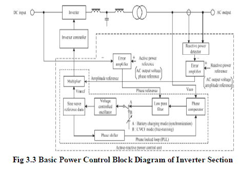 |
| For the reactive power, the sine wave reference regulated by VCO is multiplied with the signal in which the difference between reactive power reference and actual reactive power is amplified. The multiplied signal is defined as the control signal for inverter output volt by altering the reactive power reference (i.e., ac output voltage amplitude reference), reactive power control is made possible. The PLL has a superior characteristic, in that synchronization is ensured even if the wave is deformed, especially when EG shows extreme voltage wave distortion. |
| EG has a higher internal impedance, compared with the commercial ac line. Therefore, the output voltage of the EG has harmonic distortion when nonlinear loads such as switching elements, diodes and so far they are connected. However, if the wave amplitude varies, the dc voltage obtained by passing through the low-pass filter also varies; giving rise to concern that output of active power may fluctuate. |
3.3.3 DUMP POWER CONTROL |
| Following research into active-reactive power control techniques, we endeavored to devise effective control of dump power. When either wind power or solar power generation becomes greater than load, EG stops, and the bidirectional inverter as a master is operated under the CVCF condition .Then, dump power, which is defined as the surplus portion obtained after deducting load from generated power, is used as charging power for storage battery. In the course of battery charging, an advanced technique to prevent battery overcharge is required. Dump load (e.g., a resistor load or radiator), which functions to consumption dump power, is conventionally mounted in parallel with the battery or ac output point. |
 |
| However, since dump power varies continuously, it is difficult to regulate dump load by simply inputting dump load, because this hinders flexible control of battery charging. To stabilize both charging current and charging voltage of storage battery, we developed a unique advanced dump power control technique characterized by dump power regulation without any dump load. This technique allows for quick response to fluctuating dump power as well as reduction of needless dump power control, contributing to more effective use of natural energy. |
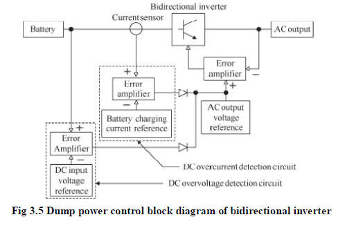 |
| If the output voltage becomes greater than the ac output voltage reference, the difference is amplified and added to the dc input voltage reference. Charging current flowing into the battery is detected by the current sensor. When the battery current exceeds the charging current reference, the difference is amplified and added to the ac output voltage reference. |
 |
3.3.4 DUMP POWER CONTROL TECHNIQUE |
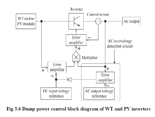
| The dump power control block diagram inverter and that of the WT and PV inverters, respectively. .When there is no dump power, the inverter acts only with ac output voltage reference. In case the larger of the outputs from dc overcurrent detection circuit and dc overvoltage detection circuit exceeds the ac output voltage reference, the diode related to the error amplifier with the larger output is turned on. Then, dc overcurrent value or dc overvoltage value is added to the ac output voltage reference, in case the output from ac overvoltage detection circuit exceeds the dc input voltage reference, the diode related to the error amplifier is turned on. Then, ac overvoltage value is added to the dc input voltage reference; thus, the inverter act. Specifically, when dump power occurs, the surplus portion flows into the storage battery through the bidirectional inverter. |
| Charging current flowing into the battery is detected by the current sensor. When the battery current exceeds the charging current reference, the difference is amplified and added to the ac output voltage reference. While, when the battery voltage exceeds the charging voltage reference, the difference is amplified and added to the ac output voltage reference. Thus, as the ac output voltage reference increases, the output voltage of the bidirectional inverter also increases. When the output voltage of the bidirectional inverter increases, the output voltages of WT and PV inverters increase through reactive power control. If the output voltage becomes greater than the ac output voltage reference, the difference is amplified and added to the dc input voltage reference. |
| With this, the phase reference as varies, allowing the PLL to control inverter voltage phase. Because the output voltages of the WT and PV inverters are designed to be controlled by the dc input voltage reference, the ac output voltage decreases as the dc input voltage reference increases. In this way, a feedback loop is formed in the proposed system. Dump power is controlled; and charging current and charging voltage in the storage battery can be stabilized. |
3.4 INTRODUCTION OF P-Q THEORY |
| The instantaneous active and reactive power theory or the P-Q Theory is widely used to design controllers for active filters. A historical background of the theory is presented and the problem caused by distorted voltages at the point of common connection (PCC) is analyzed. In addition, the appearance of source current harmonic component not present in the load current (hidden current) caused by different characteristics for the calculation of the oscillation real and imaginary power components is discussed. |
| The problem caused by the voltage distortion can be solved using a phase locked loop (PLL) circuit. These analysis and solutions are presented to clarify some aspects of the p-q Theory not clear in the original approach of the theory. One advantage of applying the αβ0 transformation is the separation of zero-sequence components into the zero sequence axis. Naturally, the αβ0 and axis do not have any contribution from zero-sequence components. |
3.4.1 POWER QUALITY IN POWER DISTRIBUTION |
| The term power quality means different things to different people. One definition is the relative frequency and severity of deviations in the incoming power supplied to electrical equipment from the customary, steady, 50 Hz, sinusoidal waveform of voltage or current. These deviations may affect the safe or reliable operation of equipment such as computers. Thus, while not having a strict basis of measurement, terms like poor power quality generally mean there is sufficient deviation from norms in the power supply to cause equipment mal-operation or premature failure. Good power quality, conversely, means there is a low level of such deviations or mal-operations. |
| Most of the more important international standards define power quality as the physical characteristics of the electrical supply provided under normal operating conditions that do not disrupt or disturb the customer‘s processes. Therefore, a power quality problem exists if any voltage, current or frequency deviation results in a failure or in a bad operation of customer‘s equipment. However, it is important to notice that the quality of power supply implies basically voltage quality and supply reliability. Voltage quality problems relate to any failure of equipment due to deviations of the line voltage from its nominal characteristics, and the supply reliability is characterized by its adequacy (ability to supply the load), security (ability to withstand sudden disturbances such as system faults) and availability (focusing especially on long interruptions). PQ problems are common in most of commercial, industrial and utility networks. |
| Natural phenomena, such as lightning are the most frequent cause of power quality problems. Switching phenomena resulting in oscillatory transients in the electrical supply, for example when capacitors are switched, also contribute substantially to power quality disturbances. Also, the connection of high power non-linear loads contributes to the generation of current and voltage harmonic components. |
| Considering some arbitrary load, the total current consumed can be split into three components active, reactive and harmonic. Whereas the active current flow leads to real power consumption and is subsequently responsible for the energy absorbed by the system to do work, the reactive and harmonic currents do not lead to any net energy transfer. |
| While the reactive current is required to establish the magnetic medium and is responsible for the energy conversion in electrical systems, the harmonic currents are the result of the switching devices used in electronic and power electronic systems. So, it is evident that one cannot do away with the reactive and harmonic currents. However, since the net energy transfer due to them (during any given fundamental period) is zero, it is not required that these currents have to be taken from the grid. It must be noted that, the zero energy transfer we are talking about is at the PCC. That is, losses at the generation, transmission and distribution systems do exist when loads draw reactive and harmonic currents. In order to bring down these losses, the utility companies require the user to absorb a nearly purely active current. |
IV. SIMULATION RESULTS |
| The dump power control technique developed can be summarized as follows: |
| 1) dump load can be eliminated |
| 2) Effective dump power control without dump load to prevent battery overcharging is possible, contributing to extended battery life |
| 3) Since dump power data is interactively exchanged through the power line, a private communication line between different power sources is unnecessary, resulting in a simple hybrid system arrangement. |
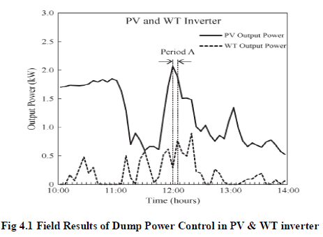 |
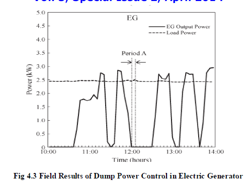
| Fig. 4.1 shows such data from 10:00 to 14:00 on a day when dump power occurred. In this test, EG started when battery remaining capacity fell to about 25% or below, and EG stopped when capacity exceeded about 30%. The output power of the bidirectional inverter was positive during discharge and negative during charge. |
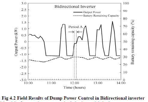 |
| “Period A” indicated in this figure shows a period during which dump power controller worked. In the period, EG did not operate, and dump power occurred because power generated by PV and WT exceeded power consumption. The fact that the bidirectional inverter had negative output power during this period shows that the battery was charged. It can be seen in Fig. 4.2 and Fig. 4.3 that dump power controller worked since the battery kept its charging power constant. |
 |
V.CONCLUSION |
| The proposed micro-wind energy conversion scheme with battery energy storage, with an interface of inverter in current controlled mode for exchange of real and reactive power support to the critical load. The hysteresis current controller is used to generate the switching signal for inverter in such a way that it will cancel the harmonic current in the system. The exchange of wind and solar power is regulated across the dc bus having energy storage and is made available under the steady state condition. This also allows the real power flow during the instantaneous demand of the load. |
| The scheme maintains UPF and also harmonic free source current at PCC in the distributed network. The suggested control system is suited for rapid injection or absorption of reactive/real power flow in the power system. The battery energy storage provides rapid response and enhances the performance under the fluctuation of wind-solar output and improves the voltage stability of the system .This scheme is providing a choice to select the most economical real power for the load amongst the available wind-battery-conventional resources and the system operates in power quality mode as well as in a stand-alone mode. Thus the proposed scheme in the grid connected system fulfils the power quality requirements and maintains the grid voltage free from distortion and harmonics. |
| The system, through ac system interconnection, will also allow flexible system expansion in the future. Further, power sources including EG can be flexibly interconnected anywhere through the same power line, and power quality stability can be maintained by controlling the phase and amplitude of ac output voltage. It is expected that this hybrid system into which natural energy is incorporated, and which makes use of various power control techniques, will be applicable in rural locations, even those with poor communications media. The system will also contribute to global environmental protection through application on isolated islands without any dependence on commercial power systems. The proposed control scheme for grid connected hybrid wind and solar power energy system to improve power quality is using for conventional control of PID controller, which is compensate critical load and reactive power demand. Under our dump power control, regulation of output is done without battery overcharging, and effective use of surplus power is made possible. This contributes to battery life extension and realization of a low-cost system. The system, through ac system interconnection, will also allow flexible system expansion in the future. Further, power sources including EG can be flexibly interconnected anywhere through the same power line, and power quality stability can be maintained by controlling the phase and amplitude of ac output voltage. It is expected that this hybrid system into which natural energy is incorporated, and which makes use of various power control techniques, will be applicable in rural locations, even those with poor communications media. The system will also contribute to global environmental protection through application on isolated islands without any dependence on commercial power systems. |
References |
|