ISSN ONLINE(2319-8753)PRINT(2347-6710)
ISSN ONLINE(2319-8753)PRINT(2347-6710)
P.Kiruthika1*, S.Balasubramanian2, M.C.Sundarraja1, J.Jegan4
|
| Related article at Pubmed, Scholar Google |
Visit for more related articles at International Journal of Innovative Research in Science, Engineering and Technology
Over the past few decades, concrete filled steel tubular (CFST) column plays an eminent role in the construction industry owing to its structural behaviour like large deformation and energy absorption capacity. But these members get deteriorated due to the environmental effects like corrosion and ageing. The external strengthening of using fibre reinforced polymer (FRP) material is emerging as a new trend in enhancing the structural performance of CFST members to counteract the drawbacks in using the past rehabilitation work. In this paper, an experimental investigation has been carried out to investigate the behaviour of FRP strengthened slender circular CFST members under compression. The size of the specimens includes 42.4mm diameter, 3.2mm thickness and 1500mm height. In the experimental work, three columns are externally bonded by 200mm width of CFRP strips with the spacing of 60mm and another three columns with 300mm width and 100mm spacing. Experiments are undertaken to examine the interaction of FRP with CFST columns in terms of the failure modes, axial load Vs lateral deformation and enhancement in load carrying capacity. At the end, the results demonstrated that there is an improvement in the behaviour and the load carrying capacity of CFST columns by strengthening those externally using FRP composites.
Keywords |
| CFST members, circular, compression, FRP composites, slender, strengthening. |
INTRODUCTION |
| Composite construction incorporates the adverse property of steel which has high tensile strength and ductility with the concrete having high compressive strength, excellent fire resistance and low cost. The composite construction is very often adopted in super high rise building, long span bridges and roof structures owing to its high structural efficiency with large strength to weight ratio as well as large flexural rigidities against instability and serviceability problems. Among the composite members, the composite column is gaining importance because of its wide applications over bridge piers subjected to impact from traffic, column supporting storage tanks, columns in high rise buildings, railway decks, piles and offshore structures (Shanmugam & Lakshmi). |
| Composite column exists in two forms; i) steel encased concrete section ii) concrete filled steel tubular sections. Concrete filled steel tubular (CFST) column is a load bearing member with concrete filled inside bare steel tube. CFST columns are preferred over concrete and steel columns because of its high axial load carrying capacity, better ductile performance, large energy absorption capacity and lower strength degradation (Jianming Liu). During the application of loads, the steel tube provides equal and uniform continuous pressure on the concrete core. So the concrete is subjected to tri-axial state of stress results in the enhancement of ultimate carrying capacity and stiffness of the member (Liu Dalin, Gho Wie-Min and Yuan Jie). On the other hand, the concrete prevents the inward local buckling of steel tube by increasing its local buckling strength. Circular cross sections are used over other sections due to the confinement of concrete (Kirubha Roseline.J, Dr.D.Tensing). The size of CFST column is smaller than that required for RC columns to support same loads. Because of its high resistance for a small cross sectional area, it maximizes the useable floor area. The need of longitudinal reinforcement, transverse reinforcement and formwork are satisfied with the structural behavior of steel tube and it tends to rapid construction (V. Kvocak, G. Varga and R. Vargova). |
| The main disadvantage of CFST is, when the column is subjected to maximum load, the steel tube dilates more from its actual position than that of concrete. It results in lack of confining pressure causes reduction in the strength and stiffness of column. To minimize this effect, internal stiffeners and binding bars were proposed in the past, but the installation process is difficult for smaller cross sectional area (M. H. Lai, J. C. M. Ho). CFST column becomes unsafe to use because of the changes in loading, design configuration, inferior building materials or natural calamities (Shaikh Zahoor Khalid, S.B. Shinde, Karim .M. Pathan). The structural capacity of the column can be increased by rehabilitation and upgrading of existing infrastructure using section enlargement, external bonding of steel plates and fibers etc. Section enlargement and external bonding of steel plates are ineffective because of increase in cross section, installation difficulties and corrosion of steel plate causes de-bonding of members. These drawbacks are overcome by using external bonded fiber reinforced polymer (FRP). Initially FRP is used in marine transportation, architectural cladding, aerospace transportation, automotive components, etc. The field application of FRP for structural engineering could be traced as early as in 1960’s (Shaikh Zahoor Khalid, S.B. Shinde, Karim .M. Pathan). But the external bonding of FRP for strengthening the structural elements was worldwide in the mid of 1980’s. |
| Recent years FRP is becoming a popular material for rehabilitation due to its superior material properties like: corrosion and weather resistance, high mechanical strength, less weight, ease of handling, good fatigue resistance and ductility (J. W. Park, Y. K. Hong, et al.). Axial compressive behavior of FRP confined concrete has received significant attention over past two decades. However, research related to FRP applications to steel structures has started quite recently and there are still few applications in practice due to uncertainties concerning the long term behavior of these applications and the bonding between the composite materials and steel. |
| Hu, Y. M., Yu, T. & Teng, J. G. examined the axial compressive behavior of FRP confined CFST columns of circular cross sections. Experiments were conducted to study the influence of diameter to thickness ratio of the steel tube and the stiffness of FRP jackets. It was observed that the confining pressure provided by the FRP jackets delayed and in some cases overcome the local buckling behavior of CFST column and enhanced the strength and ductility of column under axial compression |
| Zhong Tao, Lin-Hai Han and Ling-Ling Wang presented the effect of unidirectional CFRP in repairing the fire damaged CFST members like beams and columns in terms of the load bearing capacity. The stub columns of square and circular cross sections were chosen for this study. It was observed that this repairing technique was quite notable in case of stub columns than that for beams. For beams having large bending moments or heavily damaged under fire should be underwent to other suitable methods for repairing, as CFRP jackets was not effective. |
| Chen Chen, Yinghua Zhao and Jackie Li investigated the dynamic response of CFST column specimens of different height but with same cross sectional area, strengthened by different FRP composites under impact loading using drop weight system. Out of eleven CFST columns, eight columns were wrapped with Carbon-FRP, two columns were wrapped with Glass-FRP and remaining one as control specimen. The results revealed that the impact resistance given by Glass-FRP wrapped CFST columns was notorious when compared to that by Carbon-FRP, in terms of timehistory curves of impact force, acceleration, deflection, and strain. |
| J.F. Dong, Q.Y. Wang, Z.W. Guan analyzed the solid or hollow steel tube columns in terms of confinement pressure given by the CFRP jackets. Some of the columns with square and circular cross sections were subjected to full wrapping and some by partial wrapping. Because of the reduced confining portion, the partial wrapping was not much effective that of full wrapping in improving the strength and stiffness of the column, as it restrained the hoop deformation in the successive layers. Here the height of columns considered had some notable effect on the load carrying capacity.Chunyang Zhu and Yinghua Zhao studied the composite behavior of GFRP with CFST columns under combined seismic loading. Four specimens with the same features was considered for the experiment and it was wrapped with one and two layers of GFRP in different orientations. The confining pressure given by the GFRP, improved the energy dissipation capacity and thereby reduced the rigidity degeneration rate, in case of bi-directional orientation. |
| Research over last few decades proves that the fiber composite materials, which are used for the construction and rehabilitation process has found to have engineering and economic advantages. However limited research has been reported on the strengthening of slender concrete filled steel tubular columns using FRP. More tests are required to carry out to optimize the type of FRP, its orientation, number of layers and sequence in applying. The main aim of this study is to analyze the performance of FRP strengthened CFST column in the structural aspects thereby controlling the spacing and width of FRP strips. |
II. MATERIALS PROPERTIES |
2.1 Steel |
| The hollow steel tube of slenderness ratio 141.5 confirming to IS 1161-1998 is used. It has a circular cross section with the size of 42.4mm diameter, 3.2mm thickness and 1500mm height. Its yield strength is given as 250MPa in the manufacturer specification details. |
2.2 CFRP |
| The unidirectional carbon fibre called MBrace 240, fabricated by BASF India Inc was used in this study. It is a low modulus CFRP fibre having modulus of elasticity of 240 kN/mm2 and the tensile strength was 3800 N/mm2. The thickness and width of the fibre was 0.234mm and 600mm respectively. |
2.3 Adhesive |
| The most suitable adhesive material with FRP fabrics is MBrace saturant supplied by BASF India Inc. The adhesive type consists of two compounds, a resin and a hardener with the mixing ratio was 100:40 (B: H). |
2.4 Concrete mix proportion |
| The designed mix proportion of 1:1.6:3.1 was used to attain a strength of 20N/mm2, with the water cement ratio of 0.55. The average compressive strength of was found to be 27.5N/mm2 at the end of 28days curing. |
III. EXPERIMENTAL PROGRAM |
3.1 General |
| For this research work, the mild steel tube of 1.5m height was cut out from 6m length steel tube with the circular cross section of 42.4mm diameter and 3.2mm thickness. Here the CFRP strips were used to complement the strength of steel tubes and the tubes were filled with normal strength concrete. Six specimens were tested under axial compression to optimize the need of CFRP strips in view of width, spacing and number of layers. The following designation was used to identify the specimens: CS, CF-200-60-1, CF-200-60-2, CF-200-60-3, CF-300-100-1, CF-300- 100-2 and CF-300-100-3. For example, the CF-200-60-1 specifies that carbon fibre strip having a width of 200mm and spacing of 60mm with one layer. CS specifies control specimen. |
3.2 Fabrication of Specimens |
3.2.1 Casting and Curing of CFST specimens |
| The steel tube of circular cross section with 42.4mm diameter, 3.2mm thickness and 1500mm height was made from the 6000mm length of steel tube. The linear surface-grinding machine was used to smoothen the end portion of the steel tube. Rust and loose debris presented inside the steel tube were cleaned completely using steel wire brush. Concrete was filled inside the steel tube, with bottom end closed with the steel plates, so as to prevent the leakage of slurry and thoroughly compacted, to keep it free from air gaps. Then the specimens were kept under the process of wet curing. |
3.2.2 Surface Preparation |
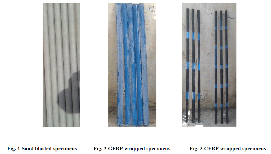
| The surface of the CFST specimens should be coarse enough to bond with the FRP composites, for proper interaction. Initially the surface was wire brushed to devoid it from loose matters. Then the specimens were subjected to sand blasting, to make the surface better for bonding and finally cleaned with acetone solution. The sand blasted specimens were shown in Fig. 1. |
3.2.3 Application of CFRP Composites |
| The adhesive was prepared, by mixing the base and hardener proportionately and a single coat was applied over the surface. Before getting dried, the surface was wrapped with a layer of glass fiber to avoid the direct contact between carbon and steel so as to prevent galvanic corrosion that is shown in Fig. 2. After that, CFRP strips of mentioned width and layers were bonded with their respective spacing. During wrapping, air may get entrapped and so it was cleared in the fibre direction, by ribbed roller. Finally, the specimens were allowed to cure for the period of 10 days under room temperature. The CFRP strips wrapped specimens are shown in Fig. 3. |
3.3 Instrumentation and Test Procedure |
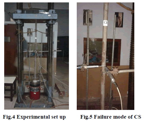
| All the specimens were tested under axial compression in a column tester of 2000kN capacity. The columns were placed, centered and levelled using spirit level and plumb bob. Linear voltage displacement transducers (LVDT) were used to observe the lateral deformation. A 16-Channel Data Acquisition System was used to store the data acquired from the load cell and LVDTs. To begin with the test, a 20kN load was applied and removed to make the column rest on their base. Then the experimentation was begun with the increment of loads at regular intervals. The experimental set up is shown in Fig. 4. The failure modes, lateral deformation and failure load were recorded up to its ultimate load. |
 |
 |
IV. EXPERIMENTAL RESULTS AND DISCUSSION |
| The parameters considered for the investigation of CFRP bonded CFST columns included the width, spacing and the number of layers in order to optimize its usage. Experimentations results were reviewed, in the aspect of above said parameters. The lateral deformation behavior and load carrying capacity were observed and discussed. |
4.1 Failure modes |
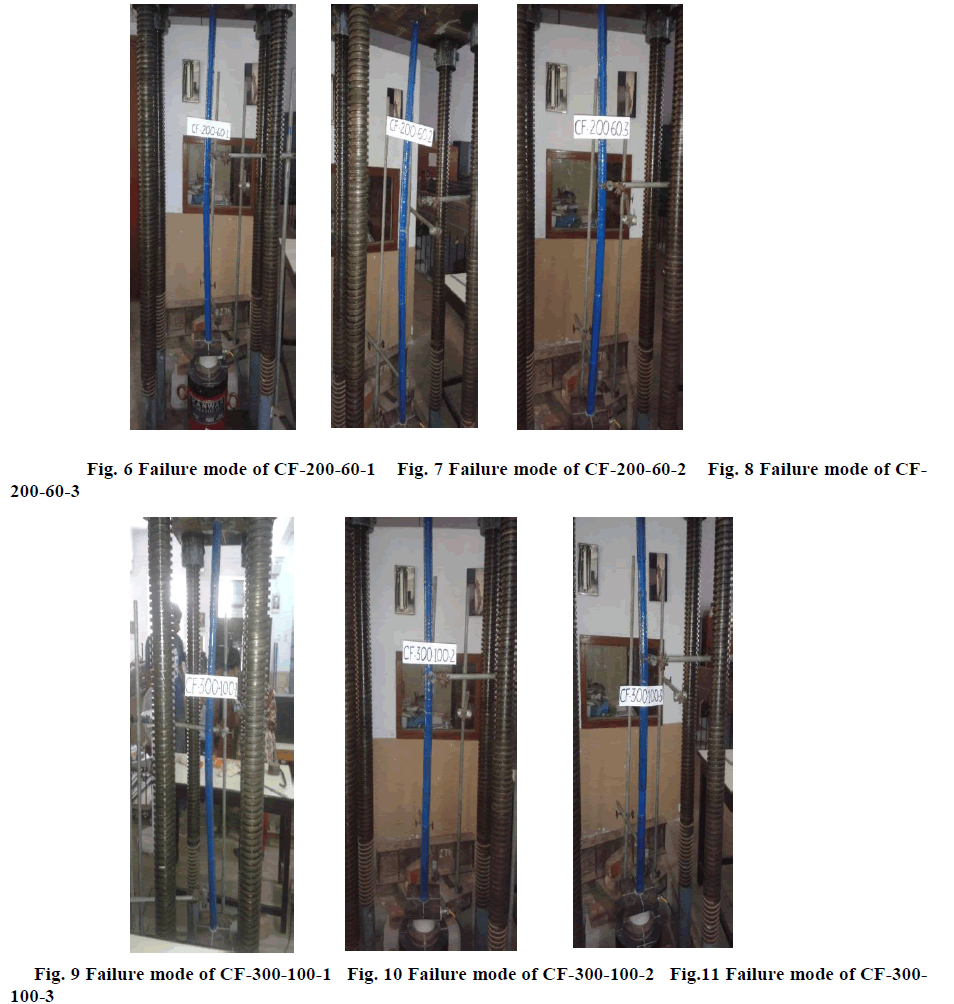
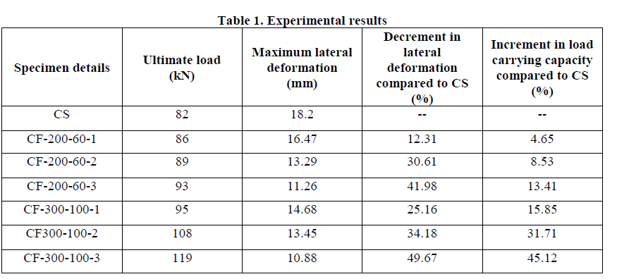
| All the CFST column specimens were tested to observe the response of CFRP strips under ultimate loading. Under increased loading, concrete pushed the steel tube outwards leaded to overall buckling of steel tube. On the other hand, in-filled concrete prevented the inward buckling of steel tube. At the load of 82 kN, outward buckling of steel tube resulted in case of control specimen at its mid height was shown in Fig. 5. The slenderness of the CFST specimens was one of the major reasons for the insufficient stiffness. In general, overall buckling, resin crushing and fibre rupture were the common failure modes observed. The 200mm width of CFRP wrapped specimens such as CF-200-60-1, CF- 200-60-2, and CF-200-60-3 exhibited overall buckling of steel tube succeeded by crushing of resin prior reaching the respective ultimate load of 86 kN, 89 kN and 93 kN which is shown in Figs. 6 to 8. The lateral deformation was controlled (11.26 mm) in the case of specimen CF-200-60-3 when compared with the control specimen (18.2mm). The specimens such as CF-300-100-1, CF-300-100-2 and CF-300-100-3 were failed by overall buckling at the load of 95 kN, 105 kN and 119 kN respectively and is shown in Figs. 9 to 11. The crushing of resin with loud sound followed by rupture of fibres was observed at the mid height of unwrapped portion in the above specimens. Besides, delamination of fibres was not observed in any of the specimens, which showed that there was a proper bonding action found between steel tube and fibre. After the rupture of fibres taken place and because of the absence of confinement pressure by CFRP strips, there was no increment in the load capacity of CFST specimens. The lateral deformation of 9.16 mm and 11.98 mm were recorded for CF-300-100-3 and CF-300-100-2 specimens, at the corresponding failure load of control specimen. From the above observations, it was understood that the CFRP strips helped in enhancing the behavior of CFST columns, by delaying the overall buckling under its peak load. The failure of CFRP wrapped CFST specimens of 300 mm width were occurred due to the reduced confinement area provided by increased spacing of CFRP fibre strips. On the other side, the deflection was delayed due to the increased wrapped zone width. |
4.2 Load Vs Lateral deformation |
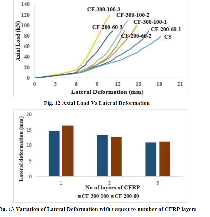
| The CFST specimens bonded with CFRP fibre sustained higher strength and greater lateral deformation control than the control specimen which is shown in Fig. 12. This beneficial effect of confinement by CFRP fibres in arresting the lateral deformation was moderate due to slenderness of the columns. The maximum lateral deformation of control specimen was 18.2mm at the ultimate load of 82 kN. But this lateral deformation was controlled to 10.88mm in case of CFST columns wrapped with three layers of CFRP strips of 300mm width spaced at 100mm. |
 |
| At the respective failure load of control specimen, the lateral deformation of 13.62mm, 11.98mm and 9.16mm was observed in the case of columns CF-300-100-1, CF-300-100-2 and CF-300-100-3 respectively. The percentage reduction in control of lateral deformation of above specimens is 19.34%, 27.75% and 40.22% compared with control column. Similarly, in the case of another set of columns CF-200-60-1, CF-200-60-2 and CF-200-60-3, the percentage reduction in control of deformation was 12.31%, 30.61% and 41.98% when compared to control column with the maximum lateral deformation of 16.47mm, 13.29mm and 11.26mm was observed respectively. The variation in lateral deformation for increasing number of layers was shown in Fig. 13. While comparing CF-300-100-1 with CF-200-60-1 columns, CF-300-100-1 (19.34%) had more percentage of reduction in lateral deformation than CF-200-60-1 (9.51%), as the width of wrapped zone was higher in case of CF-300-100-1. Among all columns, CF-300-100-3 exhibited more percentage (40.22%) in control of deformation, which is due to increase in confinement pressure provided by the three layers of CFRP strips than that by one and two layers. From the graph, it was concluded that the CFST columns with 200mm and 300mm width of CFRP strips to corresponding spacing of 60 mm and 100 mm was used effectively in case of controlling the lateral deformation of CFST columns under axial compression. |
 |
4.3 Load carrying capacity |
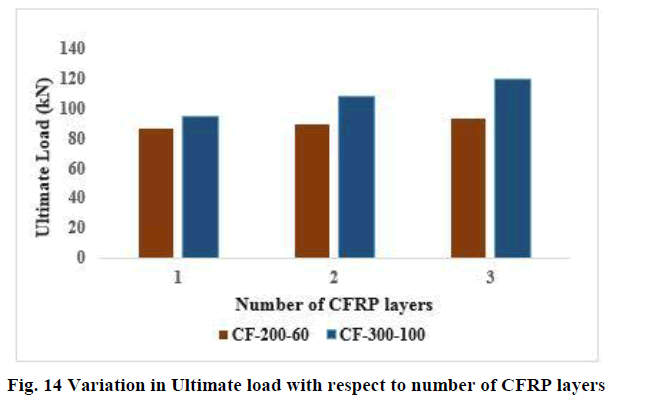
| The main aim of this research work is to improve the load carrying capacity of CFST specimens by bonding them externally using CFRP strips. It was also achieved, as there was considerable increment in the strength of CFST specimens when compared with unwrapped specimen and it given in Table 1. When compared with control specimen there was 15.85%, 31.71% and 45.12% of increase in the load carrying capacity for CF-300-100-1, CF-300-100-2 and CF-300-100-3 specimens respectively. And it was 4.65%, 8.53% and 13.41% for specimens with 200mm width of CFRP strips such as CF-200-60-1, CF-200-60-2 and CF-200-60-3. These results again proved the good composite action between steel tube and CFRP fibres. The confinement pressure provided by the CFRP strips were also confirmed. It was obvious that the spacing, width and number of layers of CFRP strips played the important role in enhancing the load carrying capacity. When comparing CF-300-100-1 with CF-200-60-1 specimen, CF-300-100-1 (15.85%) had more load carrying capacity than that of CF-200-60-1 (4.65%). Similarly, CF-300-100-3 was having 31.71% more load carrying capacity than CF-200-60-3. Among the CFRP wrapped CFST specimens, CF-300-100-3 (45.12%) had greater strength than all other specimens. So it was obvious that, increasing the spacing of CFRP strips resulted in improvement in load carrying capacity, with the condition of enhanced confinement area attained by increasing width of CFRP strips. Even for the specimens having reduced spacing of CFRP strips, the number of fibre layers differentiated the ultimate load, which is due to intensity of external confinement pressure provided by them. The columns with 300 mm width specifications such as CF-300-100-1, CF-300-100-2 and CF-300-100-3 had the ultimate load of 95 kN, 108 kN and 119 kN respectively as the number of CFRP layers increased. It was similar in case of CF- 200-60-1, CF-200-60-2 and CF-200-60-3 specimens. Variation in the ultimate load for increasing number of layers was shown in Fig. 14. From the above observations, both the 300mm and 20mm width CFRP strips with the spacing of 100mm and 60 mm are more adaptable for CFST columns under axial compression. It is also clear that CFRP strips improved the axial load carrying capacity of CFST columns by external bonding. |
 |
 |
V. CONCLUSIONS |
| Longitudinal wrapping of unidirectional CFRP strips over CFST columns was put forth in this research work. The performance was observed and discussed in terms of failure modes, axial load Vs lateral deformation and load carrying capacity. Based on the axial compression tests on the CFRP wrapped CFST columns, the following conclusions can be made: |
| • The axial compressive behavior of CFRP strengthened CFST columns was enhanced both in terms of strength and stiffness, by reducing the lateral deformation and increasing the load carrying capacity when compared to unstrengthen CFST column. |
| • In case of unwrapped CFST columns, the outward buckling of steel tube was observed, as the inward buckling was prevented by in filled concrete. In addition, the overall buckling of the steel tube at the mid height was delayed and it was followed by crushing of resin and rupture of CFRP strips, for strengthened CFST columns under ultimate load. |
| • The reduction in lateral deformation of CFST columns such as CF-200-60-1, CF-200-60-2 and CF200-60-3 were 12.31%, 30.61% and 41.98% for the corresponding failure load of CS. |
| • The lateral deformation was decreased upto 38.13% than control specimen by using three layer CFRP strip width of 300 mm and 100 mm spacing. |
| • The load carrying capacity of the CFST columns was enhanced by 45.12%, 31.71% and 15.85% respectively for CF-300-100-3, CF-300-100-2 and CF-300-100-1 than that of CS. |
| • From the results, it was clear that the spacing and number of layers of CFRP strips played a dominant role in the strengthening of CFST columns, as the former controlled the confining area and the latter improved the intensity of confinement pressure. |
References |
|