ISSN ONLINE(2320-9801) PRINT (2320-9798)
ISSN ONLINE(2320-9801) PRINT (2320-9798)
Prashant R.T,1 Vani R. M2, Hunagund P.V.3
|
| Related article at Pubmed, Scholar Google |
Visit for more related articles at International Journal of Innovative Research in Computer and Communication Engineering
In this paper microstrip antenna with Complimentary Dual Split Ring Resonator (CDSRR) is designed using IE3D simulation software and measured practically. The array of 1 x 3 CDSRR is embedded in the ground plane and the study has been made by increasing the number of CDSRRs to 3 x3 configuration. The measured results shows the antenna with 3 x 3 CDSRRs behind the radiating patch is resonating at two different frequencies i.e., 5.32GHz and 9.45GHz., whereas, antenna without CDSRRs i.e., conventional antenna is resonating at 5.98GHz. The size reduction of 10.86% with return loss (RL) up to -27.33dB (|S11| < -10dB) is achieved. Along with miniaturization the overall bandwidth of 13.85% is achieved. These antennas find application in C and X-bands.
Keywords |
| microstrip patch antenna; CDSRRs; miniaturization; bandwidth; IE3D |
INTRODUCTION |
| Microstrip antennas have unique features and attractive properties such as low profile, light weight, compactness and conformability in structure. With those advantages, the antennas can be easily fabricated and integrated in solid-state devices [1-3]. Microstrip antennas are widely applied in radio frequency devices with single ended signal operation. This has recently been used in microwave design with a combination of metamaterials, either as a cover or a substrate. In modern wireless communication systems, the microstrip patch antennas are commonly used in the wireless devices. Therefore, the miniaturization of the antenna has become an important issue in reducing the volume of entire communication system. V.G. Veselago in 1968 provided a theoretical report on the concept of metamaterial (MTM). These Metamaterials are typically realized artificially as composite structures that are composed of periodic metallic patterns printed on dielectric substrates. Metamaterials have been extensively studied in the recent years, in the framework of microwave applications. Several works have been aimed towards the improvement of the performances of antennas in the microwave range of frequencies [4]. It is noted that some principal properties of waves propagating in materials with negative permittivity and negative permeability are considered [5] and high directivity can be obtained from conventional antenna using Metamaterials. |
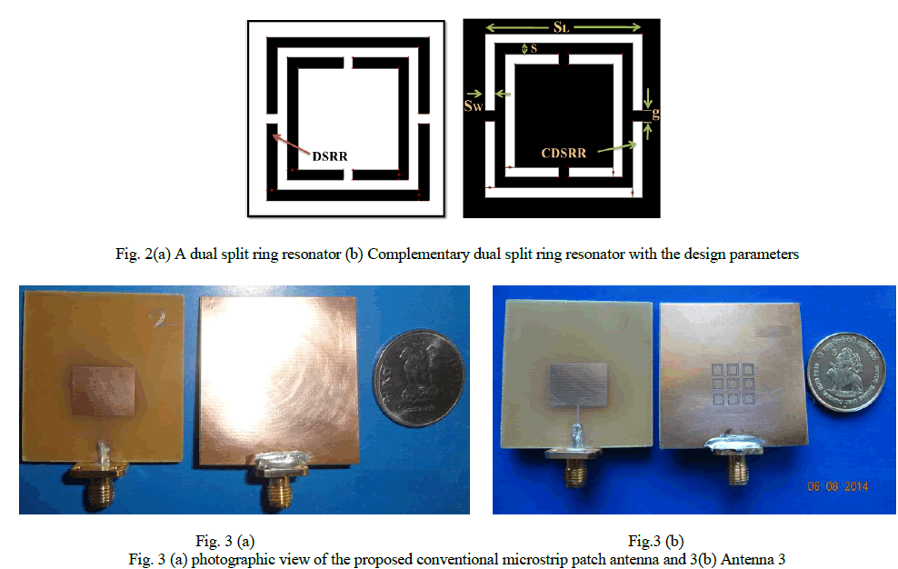
| The Metamaterial would include the SRR and CSRR has a special meaning in the field of microstrip antenna. Split ring resonators (SRR) are an integral component in realizing artificially engineered negative refractive index metamaterials. There electrical behavior is observed for an axial magnetic field for which these are seldom used in microstrip configuration. On the contrary the complementary split ring resonators (CSRR) are favorable for microstrip application as it responds to axial electric field. This property has been recently harnessed in designing planar microwave components [6-7]. Here in this work the complimentory dual spilt ring resonator (CDSRR) have been realized on the ground plane of a rectangular microstrip antenna (RMSA) and the corresponding behavior have been studied using method of moment full wave electromagnetic simulation software IE3D™. In IE3D any polygon on the ground is layer treated as a slot [8]. A Dual split ring resonator (DSRR) and its complementary are illustrated in Fig. 2. The complementary is the etched out portion of the DSRRs in the ground plane. In this paper, the miniaturized microstrip patch antenna with CDSRRs is presented. |
DESIGN OF ANTENNA AND DS-CSRR STRUCTURE |
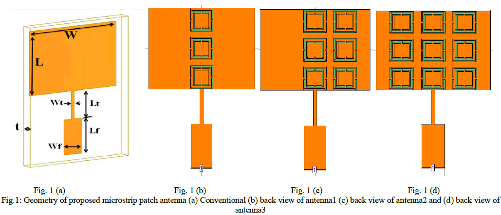
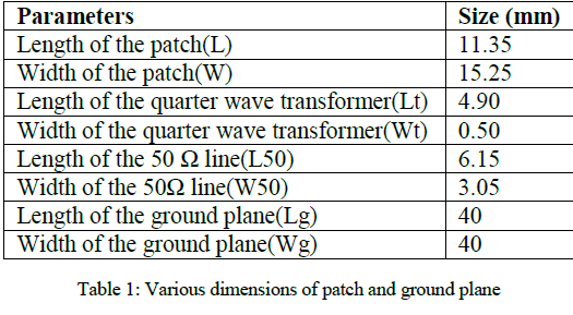
| Fig. 1(a) shows the geometry of the proposed conventional microstrip antenna, with a low cost glass epoxy FR4 dielectric material with relative permittivity (εr) of 4.4 with thickness (h) of 1.6mm is chosen. The conventional MSA is designed for 6 GHz with dimensions L and W radiating part, which is excited by simple 50 Ω microstrip feed having dimensions length Lf and width Wf using quarter wave length transformer of dimension length Lt and Wt for their impedance matching. The length Lg and Wg of the ground plane of the antenna is calculated by Lg=6h+L and Wg=6h+ W and all the dimensions are shown in table 1. |
| The study is carried by etching square CDSRRs in the ground plane as shown in fig. 1(b). Initially the arrays of three CDSRRs are etched from the ground plane with location of (x, y) = (0, 0) mm with spacing between each CDSRRs is 0.8mm which is named as Antenna1. Next another antenna with 2 x 3 CDSRRs array is introduced with location of x = 4 mm and y= 0 mm which is named as Antenna2. Finally, the Antenna 3 which is array of 3 x 3 CDSRRs with locations x= (-4, 0, 4) mm and y= (0, 0, 0) mm with spacing between each CDSRRs is 0.8 mm are etched exactly under the area of radiating patch which is shown in Figure 1(d). By increasing the array of CDSRRs the antenna resonating frequency is shifted towards left and the size of the antenna is virtually reduced with multiple resonating points. So, the final optimized Antenna i.e., Antenna 3 which is resonating at two different frequency points. The parameters of the CDSRR is SL = 3.2mm, Sw= 0.2mm, g= 0.2mm and S= 1.6mm. Fig. 2 shows the enlarged geometry of CDSRR with variables. Figure 3 is Photographic view of the optimized microstrip patch antenna. |
 |
 |
 |
RESULTS AND DISCUSSIONS |
| The simulation is carried out by using the mentor graphics IE3D simulation software version 14.65. The parameters of the proposed antennas are measured on Vector Network Analyzer (VNA) (Rhode and Schwarz, Germany make ZVK model 1127.8651). |
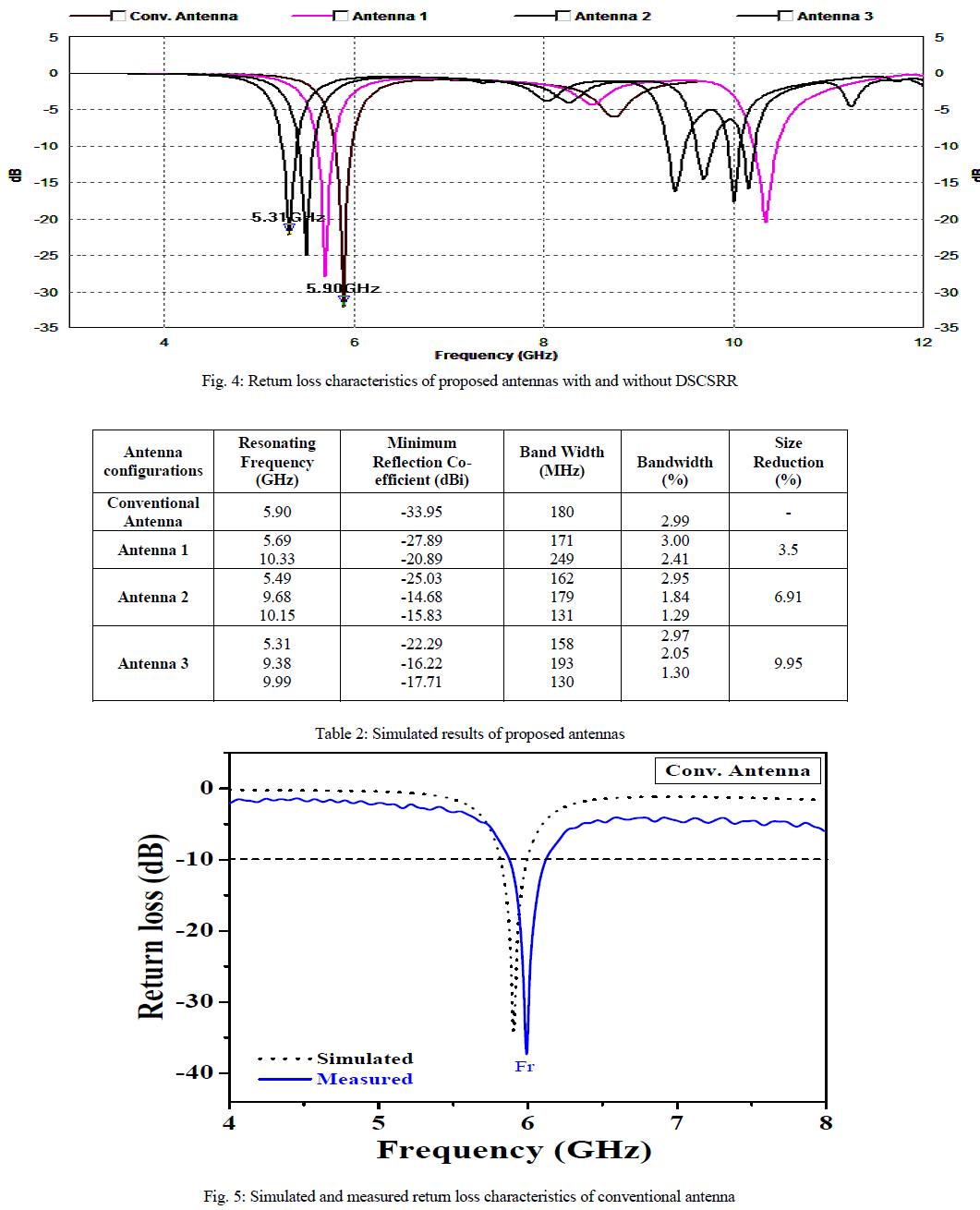
| Fig. 4 shows the simulated return loss characteristics of conventional microstrip antenna, Antenna 1, Antenna 2 and Antenna 3. From this figure it is seen that, conventional microstrip antenna resonates at 5.90GHz and the optimized Antenna 3 is resonating at 5.31GHz. The impedance bandwidth over return loss less than -10dB is determined by using the equation |
 |
| Where, f1 and f2 are the lower and upper cut-off frequencies of the band respectively, when its return loss reaches -10dB and fC is the centre frequency between f1 and f2. All the parameters of simulated results are tabulated in table 2. |
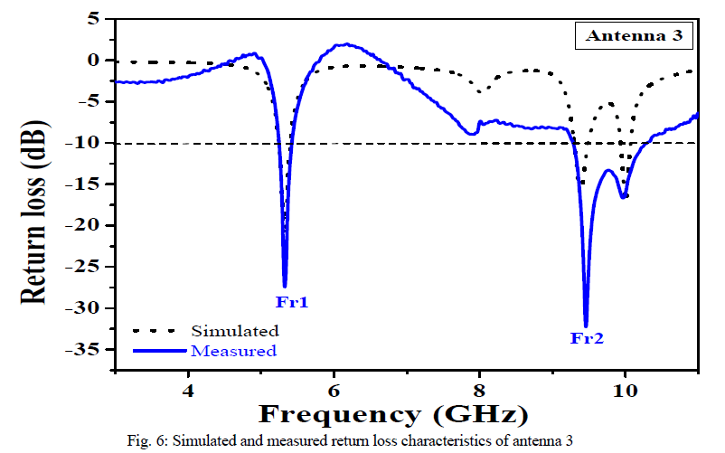
| Initially, the return loss characteristic of conventional antenna is compared with fabricated conventional antenna and which is shown in Fig. 5. The practically measured conventional antenna is resonating at Fr = 5.98GHz with 250 MHz of bandwidth. In the next step the optimized CDSRRs loaded antenna 3 is fabricated and measured, which is resonating at two different frequency points as Fr1= 5.32 GHz and Fr2 =9.45 GHz with bandwidths of 180 MHz and 990 MHz respectively. The measured return loss characteristics are compared with that of simulated values and the results are shown in table 3. Fig. 7 shows the simulated and measured return loss characteristics of the antenna 3. It is observed from the figures that, the simulated and measured results are in good agreement with each other. |
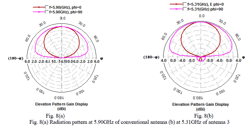
| Fig. 7(a) and Fig. 7(b) show the radiation patterns of conventional microstrip antenna and antenna 3 at their operating bands. From these figures it is seen that, the patterns are broadside in nature in both the cases. |
 |
 |
 |
 |
CONCLUDING REMARKS |
| In this work a design of metamaterial antenna based on CDSRRs has been proposed. Because of the inclusion of CDSRRs, the conventional microstrip antenna previously resonating at one frequency produces two working frequencies now. At each frequency, good matching and size reduction is obtained. A good agreement between simulated and measured results validates our design. The proposed CDSRRs antenna provides us a new way to design multi-band antennas. Besides, thanks to the presence of the CDSRRs, a size reduction and enhanced bandwidth of microstrip antenna can be achieved. |
ACKNOWLEDGEMENT |
| The authors acknowledge their thanks to UGC, New Delhi for sanctioning the IE3D simulation software under Major Research Project, which is most useful and reliable for designing microstrip antennas and DST, New Delhi for sanctioning Vector Network Analyzer for measuring the parameters of fabricated antenna. |
References |
|