ISSN ONLINE(2278-8875) PRINT (2320-3765)
ISSN ONLINE(2278-8875) PRINT (2320-3765)
Thanu James1, B.Adhavan2, Dr. C.S.Ravichandran3
|
| Related article at Pubmed, Scholar Google |
Visit for more related articles at International Journal of Advanced Research in Electrical, Electronics and Instrumentation Engineering
The Permanent Magnet Synchronous Motors are special electrical machines which can become a best replacement for Induction motor in the near future. The construction of the motor is similar to the induction motors where the stator is similar to these motors and the rotor consists of permanent magnets. A substantial air gap is generated and produced with the use of permanent magnets in the rotor for manufacturing highly competent and efficient motor drive for automation. The main disadvantage seen in these types of motors are the production of pulsation torque which increases the noise and vibration of the motor drive thereby reduces the efficiency of the drive. This paper discusses about various control techniques to reduce the torque pulsations in the motor by using the conventional PI controller and Fuzzy controller. The design and analysis of the various systems is done in MATLAB 2010b and the comparison is studied to analyse the best technique for torque ripple minimization in field oriented control in Permanent magnet synchronous motor drive.
Keywords |
| Permanent magnet synchronous motor, Proportional Integral Controller, Fuzzy Logic Controller, Space Vector Pulse Width modulation |
INTRODUCTION |
| The Permanent magnet synchronous motor (PMSM) are closely related to brushless DC (BLDC) motors whose field excitation is provided by permanent magnets and but has sinusoidal back EMF. Therefore they are considered as a combination of both Induction motors and BLDC motors as the stator construction is similar to Induction motors. These drives are mainly used in Air conditioner and AC Refrigerator compressors, washing machines, Automated Electrical power steering, Machine tools and Traction control applications. These motors are widely used in low and mid power applications such as Computer peripheral equipment’s, Robotics, Adjustable speed drives and Electric vehicles due to the advantages like high efficiency, high power factor, high power density, compactness and maintenance free operation. Also these motors are preferred over the traditional brush-type dc motors because of the absence of commutators, which minimizes mechanical wear and tear of the brushes and increases the life span of the motor. However, the main disadvantage of PMSMs is the parasitic torque pulsations. The presence of these torque pulsations results in instantaneous torque that pulsates periodically with rotor position. For the operations with reduced speed applications, these pulsations are reflected as periodic pulsations in the motor speed.There are various sources of torque pulsations in a PMSM such as the cogging, flux harmonics, errors in current measurements, and phase unbalancing. In view of the increasing popularity of PMSMs in industrial applications, the suppression of pulsating torques has received much attention in recent years. |
| Many techniques based on both motor designs and control techniques have been proposed in literature to diminish the torque ripples in the PMSM [8]. Nonlinear torque controller centered on flux/torque estimate is introduced to reduce the influence of the harmonics of the flux. The effect of the cogging torque is minimized at lower motor speed using internal model principle and adaptive feed forward compensation technique. The disadvantage is that the practical implementation of the model requires additional work [7]. The torque ripples are parasitic and can lead to torque pulsations, vibrations and noise. These effects are analyzed and modeled using the complex state-variable method. A fast current control system is produced to produce high-frequency electromagnetic torque components for compensation [6]. |
| An embedded phase domain model is used to reducethe numerical instabilities of the system. Both the conventional and embedded phase domain model models are shown to provide identical results in the steady state and transient situations; however the conventional model becomes unstable quickly if the time-step is increased [5].An application of intelligence strategy like fuzzy logic is used to reduce the torque ripples associated with direct torque control in PMSM [9]. |
FIELD ORIENTED CONTROL |
| Field oriented control is an efficient method to control a PMSM in adjustable speed drive applications with quickly changing load in a wide range of speeds including high speeds where field weakening is required. It demonstrates a synchronous motor to be controlled like a separately excited dc motor by the orientation of the stator mmf or current vector in relation to the rotor flux. |
| Field oriented control consists of vectors to control the stator currents. This control is based on projections which transform a three phase time and speed dependent system into a two co-ordinate (d and q co-ordinates) time invariant system. These projections lead to a structure analogous to that of a DC machine control. The field orientated controlled machines need two constants as input references: the torque component (aligned with the q coordinate) and the flux component (aligned with d co-ordinate). This marks the control in every working operation (steady state and transient) and independent of the limited bandwidth mathematical model. Thus it solves the classic scheme problems, in the following methods: |
| 1. The ease of reaching constant reference (torque component and flux component of the stator current). |
| 2. The ease of applying direct torque control, because in the (d,q) reference frame the expression of the torque is: |
| By maintaining the amplitude of the rotor flux (ΨR) at a constant value, we have a linear connection between torque and torque component (isq). We can then control the torque by controlling the torque component of stator current vector. The three-phase voltages, currents and fluxes of AC-motors can be analysed in terms of complex vectors in space. Considering that ia, ib, ic are the stator phase currents, |
| This current space vector depicts the sinusoidal three phase system. It still needs to be converted into a two time invariant co-ordinate system. This transformation can be divided into two steps: |
| 1. (a,b,c) to (α,β) (the Clarke transformation) which outputs a two co-ordinate time variant system. |
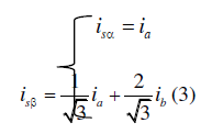 |
| The inverse Clarke transformation converts a 2-phase (α,β) to a 3-phase (isa,isb,isc) system. |
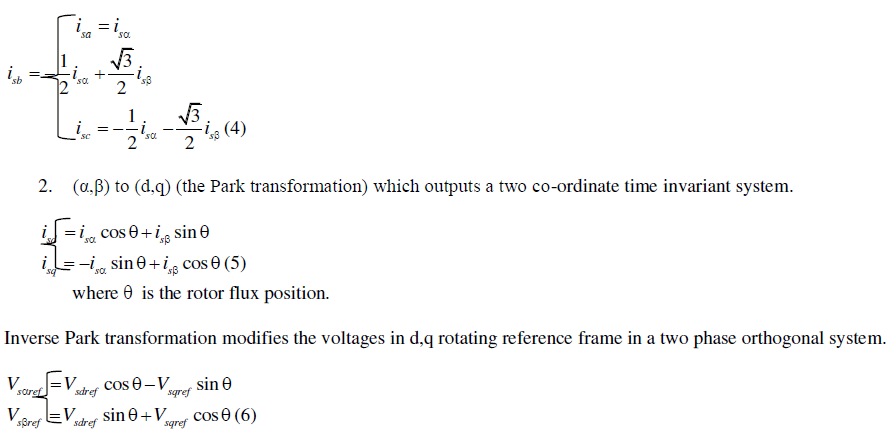 |
CONTROL TECHNIQUE I - PI CONTROLLER WITH HYSTERESIS PULSE WIDTH MODULATION |
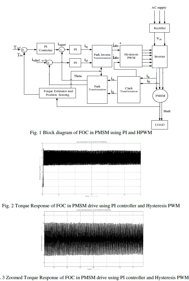
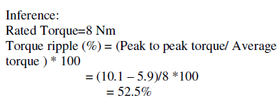
| Proportional and Integral (PI) controllers were developed because of the desirable property that systems with open loop transfer functions of type 1 or above have zero steady state error with respect to a step input. These controllers have constant parameter values which include the Proportional constant (Kp) and Integral time constant (Ki). The general approach to tune PI controllers is to have high Integral gain. And then increase the proportional constant to get satisfactory response. Start to add in integral time constant until the steady state error is removed. The block diagram of FOC in PMSM drive using PI and Hysteresis PWM is shown in the Fig. 1.The output waveform of the Control Technique I is shown in the Fig. 2 and the zoomed output response of torque is shown in the Fig. 3. |
 |
 |
CONTROL TECHNIQUE II – FUZZY LOGIC CONTROLLER WITH HYSTERESIS PULSE WIDTH MODULATION |
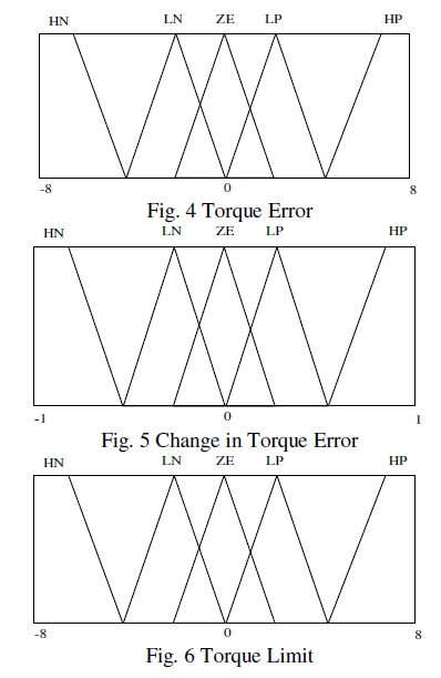
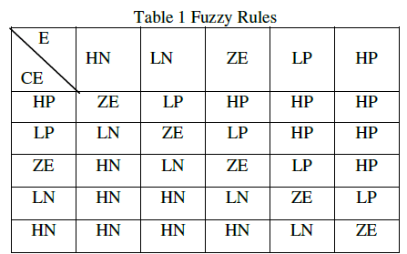
| The Fuzzy logic (FL) which is one of the soft computing techniques which works on human intelligence is defined as a multi-valued logic which deals with difficulties that have fuzziness or vague data .The fuzzy logic is a problem-solving technique that provides itself for implementation in systems ranging from simple, large, networked,embedded, acquisition and control system problems. The main principle behind fuzzy logic approach is to imitate a human decision making characteristics to solve complex problems. The inputs to the controller are Torque error and change in Torque error and the output is torque limit (T*) are described in the Fig. 4, 5 and 6. The inputs and output contain membership functions with five linguistic variables; namely HN- High Negative, LN- Less Negative, ZE- Zero, HPHigh Positive, LP- Less Positive and the rules for generating the controller is shown in the Table 1. |
 |
 |
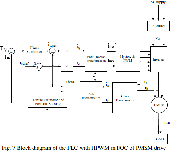
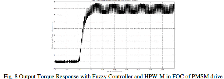
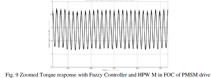
| The block diagram of the Fuzzy controller with HPWM in FOC of PMSM drive is described in the Fig. 7.The output response of Torque with Fuzzy logic controller and HPWM is shown in the Fig. 8 and the zoomed output response of the torque is also shown in the Fig. 9 to obtain the inference. |
 |
 |
 |
 |
CONTROL TECHNIQUE III – PI CONTROLLER WITH SPACE VECTOR PULSE WIDTH MODULATION |
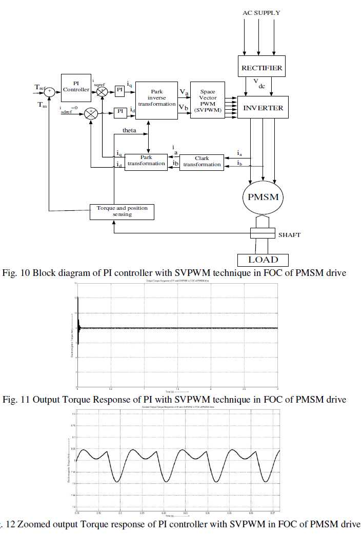
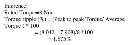
| From the literature, it has been found that Space vector modulation (SVM) is the most acceptable and widely used pulse width modulation techniques as it eliminates the 3rd order harmonics to a greater extent. There are eight switching vectors namely from V0, V1,V2, V3till V7 which represent eight voltage structures. Here to properly distribute the voltages, they are provided with two zero vectors (V0 and V7) and the rest 6 vectors are named as Active vectors. This PWM technique estimates the reference voltage Vref by a combination of the switching patterns with the eight vectors for the inverter in Table 2. The block diagram shows the PI controller with the advanced control technique SVPWM in FOC of PMSM drive is shown in the Fig. 10. The output response of the torque is shown in the Fig. 11 and also the zoomed output response of the control technique III is explained with the inference in the Fig. 12. |
 |
 |
 |
CONTROL TECHNIQUE IV - FUZZY CONTROLLER WITH SPACE VECTOR PULSE WIDTH MODULATION` |
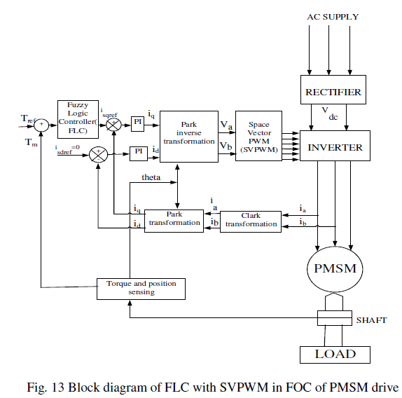
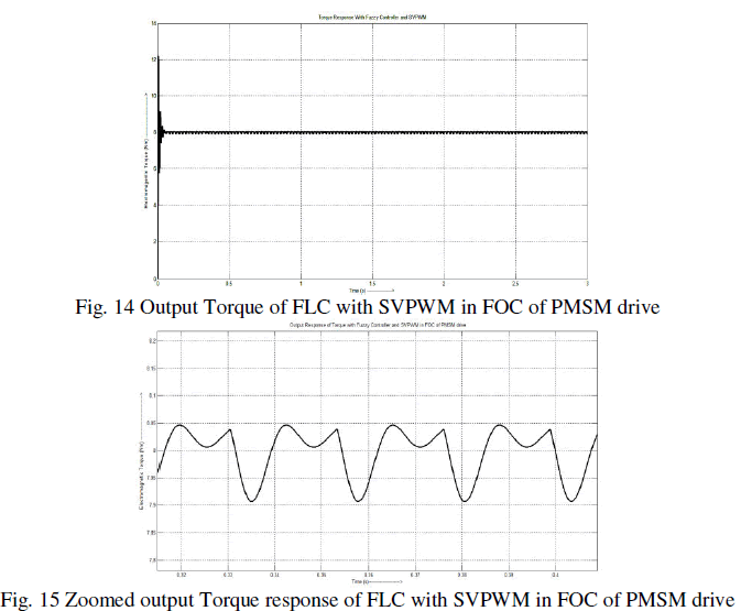
| Human experts mostly depend on common sense to solve challenging problems. Fuzzy logic (FL) is one of such intelligent control techniques which solves problems using human intelligence. Fuzzy system consists of mainly three units namely; fuzzifier, defuzzifier and an inference engine. The fuzzifier unit converts the crisp data into fuzzy data. This fuzzy data with the help of fuzzy rules is given into to the fuzzy inference engine. The engine evaluates the input and produces appropriate fuzzy output. Then the defuzzifier unit converts this fuzzy input into human understandable crisp data. Fuzzy logic has found importance due to the efficient behaviour and they are mainly used in Automation applications. Here the block diagram of Fuzzy logic Controller with SVPWM technique in FOC of PMSM drive is shown in the Fig. 13. The output Torque response of control technique IV is shown in the Fig. 14 and the zoomed output torque response is shown in Fig. 15 to obtain the inference of the technique. |
 |
 |
 |
DISCUSSION |
| It is clear that the variation in Torque shown in Table 3 is less in case of Fuzzy logic controllers and they can achieve a minimum torque ripple than other control techniques. |
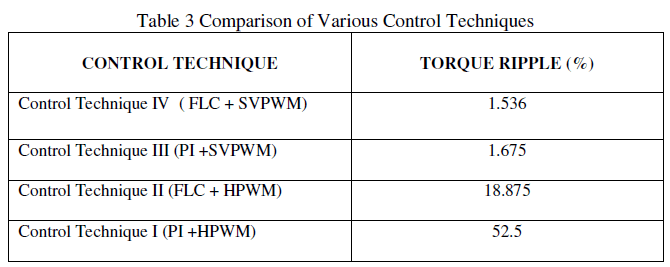 |
| It has been viewed that the control strategy IV has helped in reducing the torque ripples from 52.5% to 1.536%. Thus by using FLC based controller, ripples are reduced to a greater extent. |
CONCLUSION |
| Fuzzy logic controller based Torque controller model of PMSM motor drive have been analysed and simulated using MATLAB 2010b and the results have been presented to visualize the comparison between various control techniques. The results obtained from control technique IV demonstrate fast and satisfactory response with load perturbation. In future implementation, Hybrid PI-Fuzzy controllers can be used in replacement to PI controller. |
ACKNOWLEDGEMENT |
| I would like to extend my earnest thanks and gratitude to my project supervisor Prof. B. Adhavan for his constant support and encouragement during the course of my project. I’m truly overwhelmed by his honored guidance and inspiration from the beginning to the end of this project. |
References |
|