ISSN ONLINE(2278-8875) PRINT (2320-3765)
ISSN ONLINE(2278-8875) PRINT (2320-3765)
S.Subanitha , M.Ramkumar
|
| Related article at Pubmed, Scholar Google |
Visit for more related articles at International Journal of Advanced Research in Electrical, Electronics and Instrumentation Engineering
The Trans-Z-source inverters has features such as DC input source and reduced capacitor counts. In the proposed system,photovoltaic module implemented instead of DC source in the trans Z source inverter.The battery is connected across the Capacitor which acts as the energy storage device.With the energy storage device,inverter is able to operate even in the case,the available PV power is higher than the load power and also when available PV power is lower than the load power.Here the power not consumed by the load can be used to charge the battery.The main advantage of this system is because of the implementation of the battery bank, voltage regulation takes place and oscillations on the AC grid can be reduced.In addition to this,it has benefits of high voltage gain and reduced voltage stress
Keywords |
| Z;source inverters, voltage-source inverter (VSI), trans-Z-source inverters(TZSI),Photovoltaic(PV) module. |
INTRODUCTION |
| Inverter denotes a class of power conversion circuits that operates from a DC voltage or DC current source and converts it into AC voltage or current. Static power converters are constructed from power switches and the AC output waveforms thus take discrete values. However this waveform is not sinusoidal.By employing a modulation technique that controls the time and sequence of the power switches used, the output voltage waveform obtained is more sinusoidal with less harmonic distortions. The modulating techniques mostly used are Sinusoidal pulse width modulation, space vector technique and selective harmonic elimination technique. |
| The main drawback of the voltage source inverter is the requirement of the dead time to prevent the shootthrough of upper and lower switching devices of each leg. And also the obtained ac voltage cannot exceed the dc source voltage for rectifying this dc-dc boost converter is required. In the Z – source inverter [1], the network employs a unique impedance circuit to couple the converter main circuit to that of the power source in order to obtain the unique features that cannot be achieved using conventional VSI or CSI. The Z-source inverter (ZSI)[5] has been reported suitable for residential PV system because of the capability of voltage boost and inversion in a single stage. |
| The Z-source inverter has the main disadvantage that the current drawn from the source is discontinuous.The ZSI and QZSI [2] has all the advantages over voltage source inverters. Here, trans ZSI [3] is presented in this paper which have some advantages such as required potential in the applications with very low input voltage. The trans-Z-source inverters can be obtained from either voltage/current fed Z-source inverters. It can be controlled by using PWM techniques suitable to the Z-source inverters[4]. This paper deals with the derivation of the voltage fed trans-Z-source invertersand implementation of the PV module as the input source. |
PROPOSED INVERTER |
| In the voltage fed trans-ZSI with continuous input current two inductors can be coupled. Coupled inductor has the property of reflecting the voltage across the inductor L1 to inductor L2 through magnetic coupling. Here the coupled inductor turns ratio should be chosen as 2:1.this kind of inverters has advantages such as buck operation,boostoperation and inversion occur simultaneously without operating individually so it is also named as single stage conversion stage. |
PROPOSED SYSTEM |
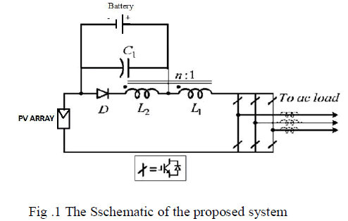 |
| The proposed system is shown in the figure 1. It consists of PV module as source input, coupled inductors, diode , capacitors and inverter part. |
OPERATION PRINCIPLE |
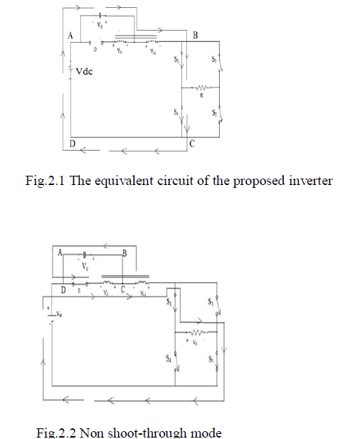
MODE 1:Shoot-through state |
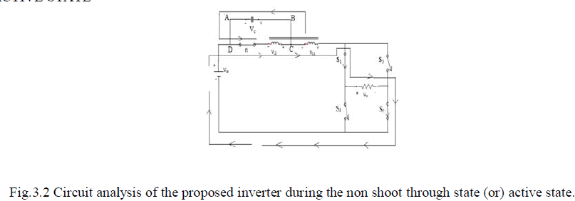
MODE 2:Active state |
 |
CIRCUIT ANALYSIS |
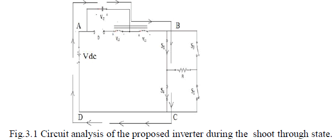
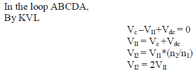
SHOOT-THROUGH STATE |
 |
 |
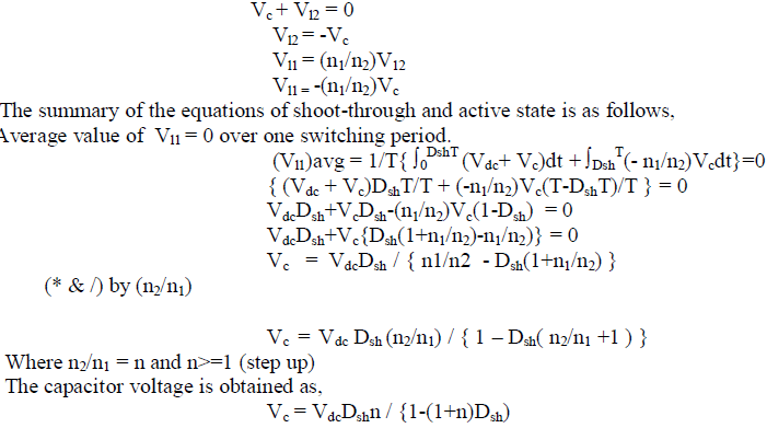
ACTIVE STATE |
 |
 |
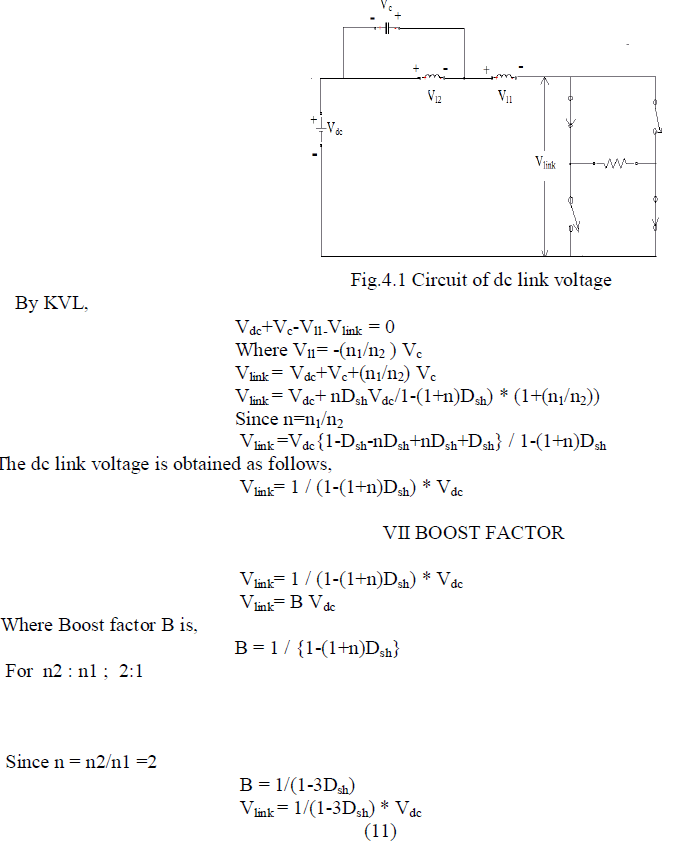
DC LINK VOLTAGE |
 |
 |
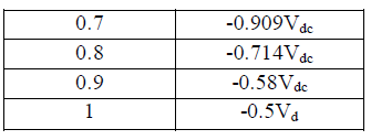 |
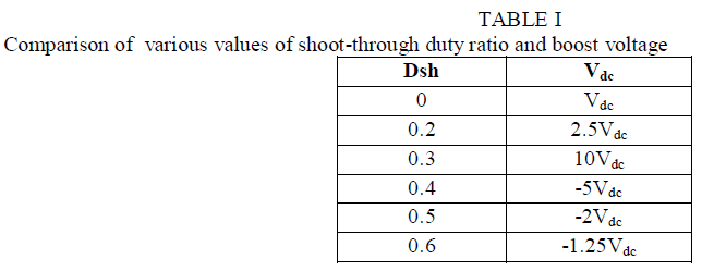
| From the above table,shoot-through duty ratio values for 0 to 0.3 we can get the promisable potential value of the boost voltage. |
PARAMETER DESIGN |
 |
MODELLING AND SIMULATION USING PSIM |
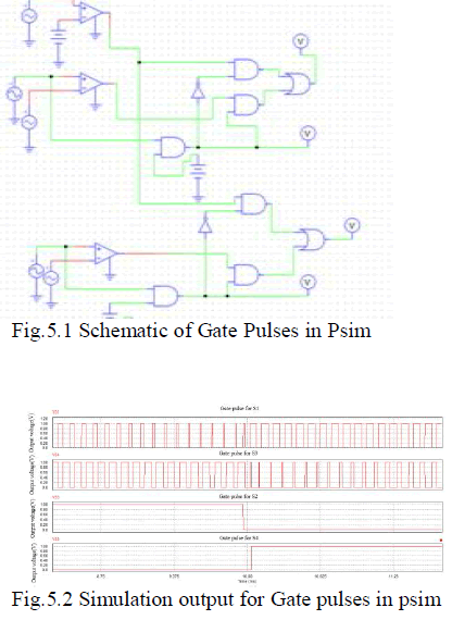
GATE PULSE GENERATION IN PSIM |
OUTPUT |
 |
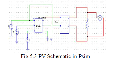
PV MODEL IN PSIM |
 |
 |
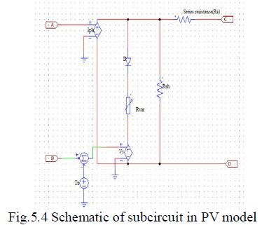
SUBCIRCUIT IN PV MODEL |
 |
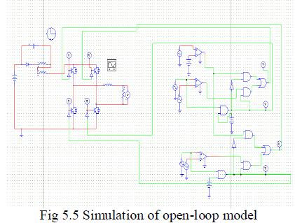
SIMULATION OPEN LOOP MODEL |
 |
SIMULATION RESULT |
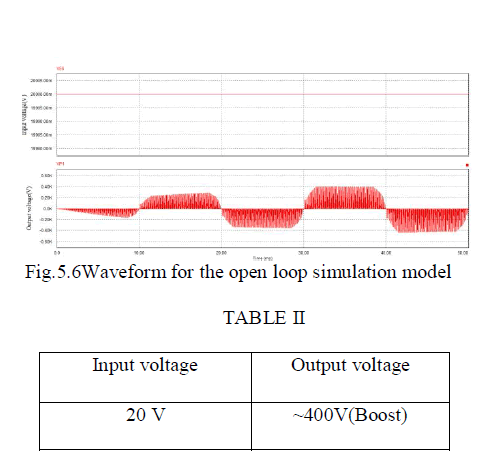 |
| For 20V input voltage 400v output voltage is obtained in the open loop. |
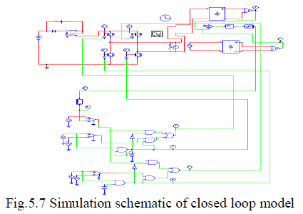
SIMULATION CLOSED LOOP MODEL |
 |
SIMULATION RESULT |
 |
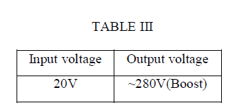 |
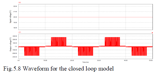
| For 20V input 280V output voltage is obtained in closed loop |
CONCLUSION |
| In this paper a new trans-Z-source inverters for photovoltaic generation is proposed.The proposed system is able to perform the buck,boost and inversion operation in single stage.Also in this proposed system components counts has been reduced when compared to all other conventional Z-source inverters so it is cost effective.The battery connected across the capacitor acts as the energy storage device even when the applied PV power is higher or lower than the available load power.If the PV power is higher the extra power which is not consumed by the load can be used to charge the battery or it is less than the load power the battery compensates the shortage of the PV power,The battery bank value should be chosen as the minimum value so it prevents the oscillation and provides voltage regulation when it is connected to the ac grid. |
| From the simulation results,we can see the characteristics of single stage conversion in the trans-Z-source inverters. |
References |
|