Keywords
|
| Cascaded H-Bridge Cells, Carrier Based Level Shifted PWM, VSC-HVDC, PI Controller, Fuzzy Controller |
INTRODUCTION
|
| The VSC topology is a high power electronics technology used in electric power systems. The introduction of VSC made evolutionary changes in power transmission through HVDC network. Now HVDC transmission is an efficient and flexible method to transmit large amount of electric power over long distances by means of overhead transmission line or underground / submarine cables. It can also be used in order to interconnect asynchronous power systems [7],[8]. |
| In the last decade, VSC-HVDC transmission systems have evolved from simple two-level converters to neutral point clamped converters and then to multilevel converters such as a modular converter. These converter evolutions are aimed to lower semiconductor losses and increase the power handling capability of VSC-HVDC transmission systems to conventional HVDC systems based on thyristor current source converter. The other goals behind new evolutions are to improve ac side wave form quality in order to minimize or eliminate ac filters, reduce stresses in voltage on converter transformers and to decrease converter overall cost and footprint[1]-[6] . |
| Here cascaded H-bridge multilevel converter is used in order to meet the requirements of the HVDC transmission system with the help of a carrier based level shifted PWM technique [13][14]. A brief overview regarding the performance of this converter in HVDC transmission system is provided in the following sections. |
CASCADED MULTILEVEL CONVERTER
|
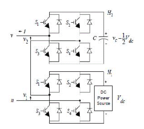
| Consider a simple cascade multilevel converter with two H-bridges as shown in Fig. 1. To operate a cascade multilevel converter using a single DC source, it is proposed to use capacitors as the DC sources for all but the first source. The DC source for the first H-bridge (H1) is a DC power source with an output voltage of Vdc , while the DC source for the second H-bridge (H2) is a capacitor voltage to be held at Vdc / 2. |
| The output voltage of the first H-bridge is denoted by v1 and the output of the second H-bridge is denoted by v2 so that the output of this two DC source cascade multilevel inverter is v (t) = v1 (t) + v2 (t). By opening and closing the switches of H1 appropriately, the output voltage v1 can be made equal to −Vdc, 0, or Vdc while the output voltage of H2 can be made equal to −Vdc/2, 0, or Vdc/2 by opening and closing its switches appropriately. |
| Here there are seven H-bridge cells (H1, H2... H7), which will be switched accordingly in order to attain 29 voltage levels by means of carrier based level shifted PWM. |
CARRIER BASED LEVEL SHIFTED PWM
|
 |
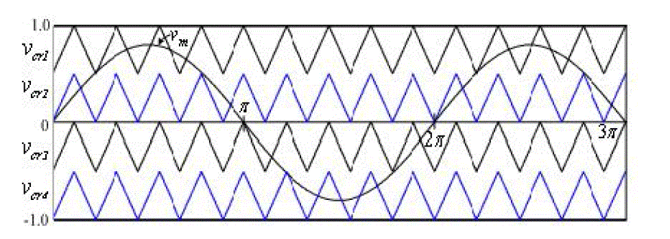
| The Fig.2 shows the Level shifted carrier pulse width modulation. Each cell is modulated independently using sinusoidal uni-polar pulse width modulation and bipolar pulse width modulation respectively, providing an even power distribution among the cells. A carrier level shift by 1/m (no. of levels) for cascaded converter is introduced across the cells to generate the stepped multilevel output waveform with low harmonic distortion. |
HYBRID MULTILEVEL VSC WITH AC-SIDE CASCADED H-BRIDGE CELLS
|
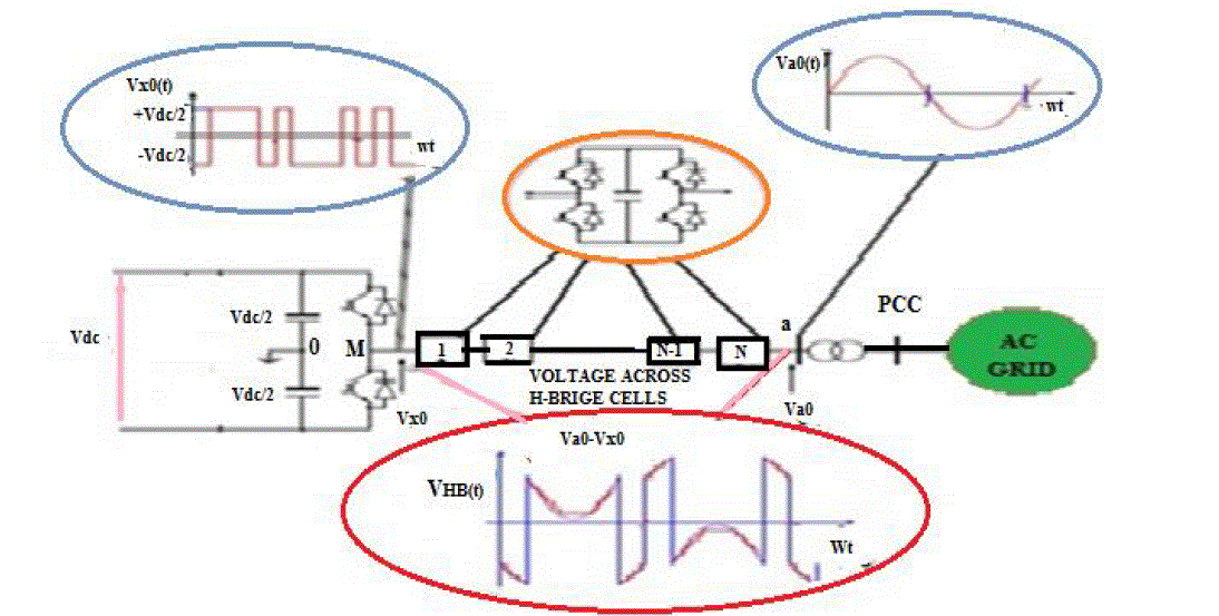
| The Fig.3 shows 1- phase of a hybrid multilevel VSC with N H-Bridge cells per phase. It can able to generate 4N+1 level at converter terminal “a” relative to supply midpoint “0”. Therefore, with a large number of cells per phase, the converter will produce a pure sinusoidal voltage to the converter transformer. |
| The H-bridge cells between “M” and “a” are operated as a series active filter to attenuate the harmonics in voltage produced by two level converter bridge. In order to minimize the conversion losses in the H-bridge cells, the number of cells is reduced such that the voltage across the H-bridge floating capacitor sum to Vdc/ 2. As a result of using less number of H-bridge cells, a small converter station is required than that of modular multilevel converter. Here a seven cell topology is used which will capable to provide 29 level voltage at converter terminal. The effective switching frequency per device is only less than 150 Hz. However the operation of hybrid multilevel VSC requires a voltage balancing scheme which ensures that the voltage across the H-bridge cells are maintained at Vdc/N under all operating conditions, where the Vdc is the total dc link voltage. |
CONTROL STRATEGY OF 29-LEVEL CONVERTER
|
| A HVDC transmission system based on a hybrid multilevel VSC with ac-side cascaded H-bridge cells requires three control system layers. The inner control layer represents the modulator and capacitor voltage-balancing mechanism that generates the gating signals for the converter switches and maintains voltage balance of the H-bridge cell capacitors. The intermediate control layer represents the current controller that regulates the active and reactive current components over the full operating range. The outer control layer is the dc voltage (or active power) and ac voltage (or reactive power) controller that provide set points to the current controllers. The current, power, and dc link voltage controller gains are selected using root locus analysis, based on the applicable transfer functions.. Fig. 4 summarizes the control layers of the hybrid multilevel VSC. Here in this topology a control system is designed for DC voltage regulation by integrating fuzzy controller with a PI controller. |
| A. Fuzzy and PI controllers |
| In case of a Fuzzy logic control scheme, the error (e =VDC, ref- ΔVDC) and integration of error signal (∫e) are used as inputs for fuzzy processing. The output of the fuzzy controller after a limit is considered as the magnitude of peak reference current Imax. This current I max comprises active power demand of the non-linear load and losses in the distribution system. |
| The peak reference current is multiplied with PLL output for determining the desired reference current. The TABLE I shows the fuzzy rule base. The rule is represented such as if e is NM and Δe is PS then u is NS. |
| In case of PI controller, the transfer function for the dc voltage controller is |
 |
| The reference current for the current controller can be obtained from the outer dc voltage controller as follows: |
 |
| where vcd and Δvcd are normalized by Vdc *. |
| Here in this topology an additional PI regulator is used to ensure that the cell capacitors are maintained at Vdc/N .Hence by considering voltage magnitude of each cell capacitor and phase current polarity, the H-bridge cells voltage balancing scheme can be realized in rotating the H-bridge cell capacitors. |
PERFORMANCE EVALUATION AND SIMULATED RESULTS
|
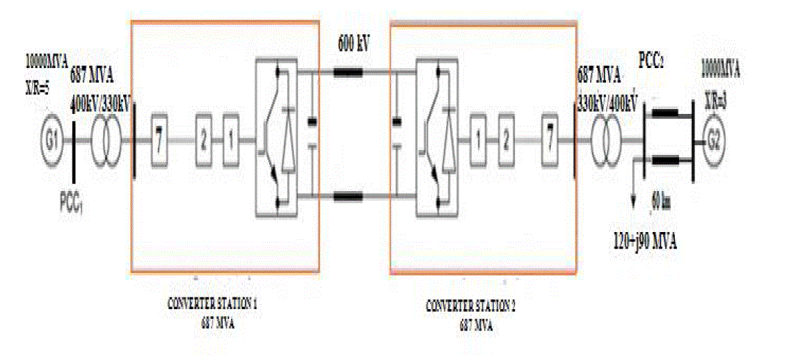
| In order to access the performance of 29 level VSC based HVDC transmission network, a test system is designed to illustrate the viability of the hybrid multilevel voltage source converter HVDC systems four-quadrant operation and voltage support as shown in Fig. 5 and simulated in MATLAB/SIMULINK environment. The waveforms demonstrating the steady state operation of HVDC system based on hybrid voltage source multilevel converter with ac side cascaded H-bridge cells is shown in fig. 6.1 to fig. 6.8. |
| For the purpose of demonstrating four quadrant operation and voltage support capability of the presented VSC-HVDC system, converter station 1 is commanded to increase its output power export from grid G1 to G2 from 0 to 0.5 pu (343.5 MW) at 2.5 pu/s. At time t=1s it is commanded to reverse the active power flow in order to import 343.5 MW from grid G2, at 2.5 pu/s. At t=2s a load of 120+j90 MVA is introduced to PCC2, illustrating the voltage support capability of converter station 2 during network alteration. |
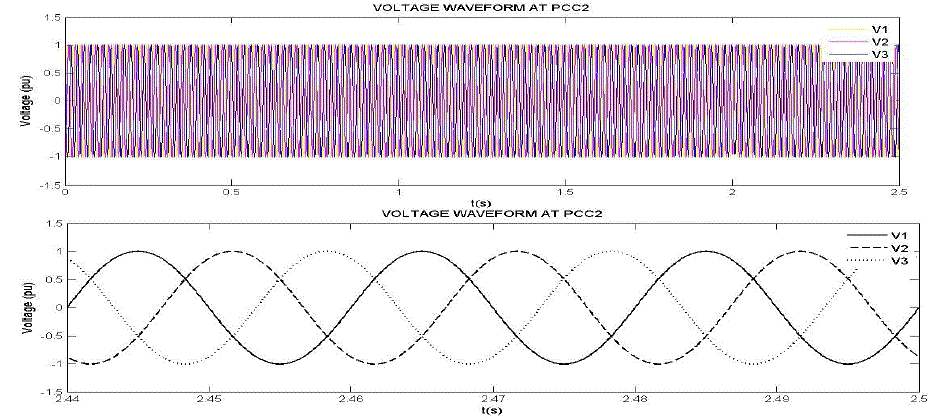
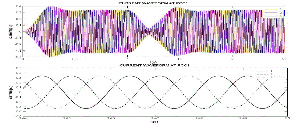
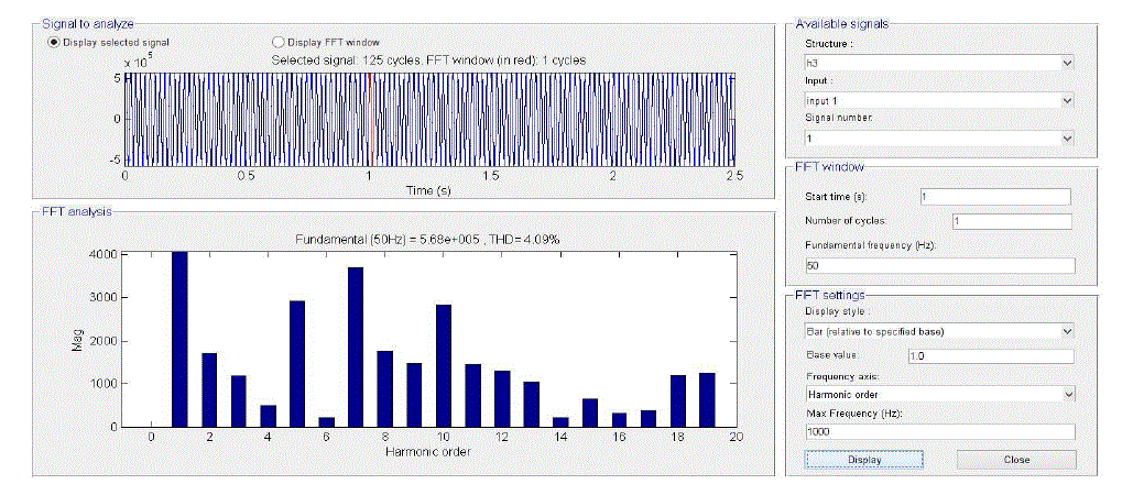
| The fig.6.1 and fig 6.2 shows the capability of converter 1 and converter 2 to exchange active and reactive power with PCC1 and PCC2 respectively. It is clear that converters are able to adjust their reactive power exchange with PCC1 and PCC2 in order to support the voltage during the entire operating period. Fig. 6.2 and fig.6.3 shows that converter 2 adjusts its reactive power exchange with PCC2 when the load is introduced at t=2 s to support the voltage magnitude. Fig. 6.4 and fig.6.5 shows that converter 2 injects and presents high-quality current and voltage waveforms into PCC2 without any need of ac filters. Fig. 6.6 demonstrates that the voltage stresses across the H-bridge cell capacitors of converter 1 are controlled to the desired set point during the entire period. Fig. 6.7 displays that the total dc link voltage across converter 2 would regulated at desired value (i.e., 600kV). The fig 6.8 shows voltage levels across a single phase, and from the waveform it is clear that the shape is nearer to pure sinusoidal. The fig 6.9 illustrates that THD of the voltage waveform is very low as compared to other converters, which is only 4.09 %. Based on these results, the proposed VSC-HVDC system is able to meet basic steady-state requirements, such as provision of voltage support and four quadrant operation without compromising the voltage and current stresses on the converters switches. |
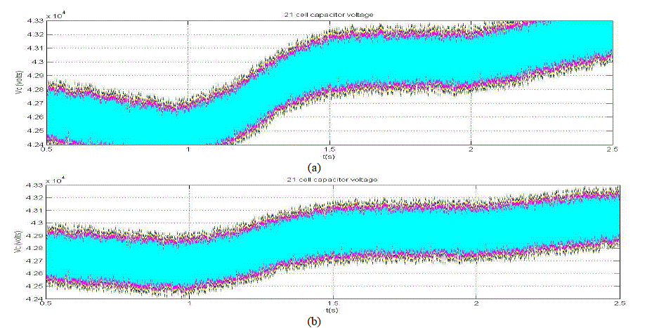
| The fig 6.10 proves the ability of a Fuzzy based PI controller to regulate the capacitor voltage more steadily. While considering the entire period, from Fig 6.6 it is found that the voltage stresses across the H-bridge cell capacitor are maintained at the set point. But still there is a small fluctuation occurs like as shown in Fig 6.10(a), due to the fact that cell capacitors contributes to regulate dc link voltage, which regulates active power. The Fuzzy controller provides better result as shown in Fig 6.10(b), since it contribute effectively to control small fluctuations, that might cause large consequences to system during network alterations. |
CONCLUSION
|
| A VSC-HVDC transmission system based on 29- level converter with ac-side cascaded H-bridge cells topology is used. The advantages of the proposed system are improved voltage profile with less total harmonic distortion ; low filtering requirements on the ac sides along with four quadrant operation and black start capability. The capacitor voltage variation has been reduced effectively by means of a Fuzzy based PI controller for DC voltage regulation, which further proves its voltage support capability. Additionally, it offers features such as smaller footprint and a larger active and reactive power capability curve than existing VSC-based HVDC systems. |
| |
Tables at a glance
|
 |
| Table 1 |
|
| |
Figures at a glance
|
 |
 |
 |
 |
 |
| Figure 1 |
Figure 2 |
Figure 3 |
Figure 4 |
Figure 5 |
| |
 |
 |
 |
 |
 |
| Figure 6a |
Figure 6b |
Figure 6c |
Figure 6d |
Figure 6e |
| |
 |
 |
 |
 |
 |
| Figure 6f |
Figure 6g |
Figure 6h |
Figure 6i |
Figure 6j |
|
| |
References
|
- Grain Philip Adam, Member, IEEE, Khaled H. Ahmed, Member, IEEE, Stephen J. Finney, Keith Bell, and Barry W. Williams “New Breed ofNetwork Fault-Tolerant Voltage-Source-Converter HVDC Transmission System” 2013 IEEE.
- G. P. Adam et al., “Network fault tolerant voltage-source-converters for high-voltage applications,” in Proc. 9th IET Int. Conf. AC and DCPower Transmission, London, U.K., 2010, pp. 1–5.
- Y. Zhang et al., “Voltage source converter in high voltage applications:Multilevel versus two-level converters,” in Proc. 9th IET Int. Conf. ACand DC Power Transmission, London, U.K., 2010, pp. 1–5.
- G. P. Adam et al., “Modular multilevel inverter: Pulse width modulation and capacitor balancing technique,” IET Power Electron., vol. 3, pp.702–715, 2010.
- G. P. Adam et al., “Modular multilevel converter for medium-voltage applications,” in Proc. IEEE Int. Conf. Electr. Mach. Drives Conf., 2011,pp. 1013–1018.
- M. Chaves et al., “New approach in back-to-back m-level diode clamped multilevel converter modeling and direct current bus voltagesbalancing,” IET Power Electron., vol. 3, pp. 578–589,2010.
- N. Flourentzou et al., “VSC-based HVDC power transmission systems:An overview,” IEEE Trans. Power Electron., vol. 24, no. 3, pp. 592–602, Mar. 2009.
- L. G. Franquelo et al., “The age of multilevel converters arrives,” IEEE Ind. Electron. Mag., vol. 2, no. 1, pp. 28–39, 2008.
- G. P. Adam et al., “Steady-state and transient performance of DC transmission systems based on HVDC technology,”in Proc. 9th IET Int.Conf. AC DC Power Transmission, 2010,pp. 1–5.
- G. P. Adam et al., “Dynamic behaviour of five-level grid connected modular inverters,” in Proc. 9th Int. Conf. Environ. Electr. Eng., 2010, pp.461–464.
- Dasareddy Mohanreddy and Tenapalli Gowri Manohar “Harmonics Mitigation and Switching loss reduction using Cascaded Multilevel BasedHalf Bridge and Full Bridge Inverter System” International Journal of Current Engineering and Technology ISSN 2277 - 4106 Vol.3, No.2 ,June2013.
- Zhong Du, Leon M. Tolbert, John N. Chiasson, and Burak Özpineci ”A Cascade Multilevel Inverter Using a Single DC Source” IEEE 0-7803-9547-6/06, 2006.
- Rammohan Rao Makineni, C.N.Bhaskar,” Simulation of Cascaded H-Bridge Multilevel Inverter Based DSTATCOM” TELKOMNIKAIndonesian Journal of Electrical Engineering, Vol. 12, No. 8, August 2014, pp. 5720 ~ 5728.
|
BIOGRAPHY
|
| Syamdev C S was born in Kerala, India. He received his B.E degree in Electrical and Electronics Engineering from Park College of Engineering and Technology, Coimbatore, Tamilnadu, in 2012 and currently Pursuing M.Tech degree in Power Systems from Saintgits College of Engineering, Kottayam, Kerala. His research interests include Power Systems, HVDC, Control Systems and Power Electronics. |
| Asst.Prof. Asha Anu Kurian was born in Kerala, India. She received her B.Tech degree in Electrical and Electronics Engineering from St. Joseph College of Engineering, Pala, Kottayam and M.Tech degree in Power Systems from Saintgits College of Engineering, Kottayam, Kerala. She is currently working as Assistant Professor in Saintgits college of Engineering, Kottayam. Her research interests include Power Systems, Power Quality, and Power Electronics. She has presented more than 8 papers in various National and International conferences. She has also published 4 papers in international journals. She is a member of IEEE. |