Keywords
|
| Wind farm, Tower, Blade and unbalanced conditions. |
INTRODUCTION
|
| Wind turbine technology has been advancing rapidly in past decades while new challenges are appearing for the future growth of the technology. The size of wind turbine has been increasing over the past decade resulting in larger and heavier subsystems and higher mechanical stresses on the turbine. In addition, force/moment sensing or accelerometers can now be installed on blades as well as the nacelle and tower to improve controllability. Design of novel advanced multivariable controllers are in need to increase the power capture and reduce fatigue loads on the wind turbine structure [1]. All the mechanical subsystems of a wind turbine exert nonlinear stresses on the wind turbine structure due to the different environmental conditions. The unequal stresses on wind turbine create mechanical vibrations in the tower and blades. These mechanical vibrations in the wind turbine causes nonlinearity in the control measures which itself being the real problem in closed loop control of the plant. If wind gust hits the blades of a turbine then instantaneous peek will be observed in the output of the wind turbine which has to be minimised immediately. Hence there is need to obtain dynamic analysis of behaviour of wind turbine under different wind speed conditions.This paper presents state space mathematical dynamic model of wind turbine structure with different wind speed pattern. The simulation analysis has been carried out using MATLAB software. From the simulation results validation study has carried out between FAST, Lumped and modified model on 5MW wind turbine HAWT (Horizontal axis-wind Turbine). |
WIND TURBINE MODEL
|
| a) Aerodynamic model |
| The mechanical power produced by the turbine on interaction with wind depends upon swept area S of the air disk formed by the rotation of the turbine’s blades S, power coefficient of performance Cp (depends upon collective blade pitch angle β and tip to speed ratio λ ), air density and wind speed V. The expression for power extracted from wind is given by [1][2],[3]-[5] the following equation. |
 (1) (1) |
| Similarly torque produced is given by |
 (2) (2) |
| Hence the equation for thrust exerted on the tower Ft is given as follows. |
 (3) (3) |
| Where Ct is the thrust coefficient, Cq is the torque coefficient, R is the radius of the rotor. Cq=Cp/ λ and λ =Rwr/V. Where Wrt is the rotor speed of turbine. Fig.1 illustrates the variation of performance coefficients of Cp and Ct. |
| To explore the wind turbine structural model and performance characteristics under different wind speed conditions a simulation model HAWT in Sim Power System tool was constructed using MATLABR 2010.The structural model which was given in [5] is based on flap wise movement of blade( ξ ) and axial vibrations of tower (y). The State Space equations for structural model of HAWT were given by [3] the following equations: |
 (4) (4) |
 (5) (5) |
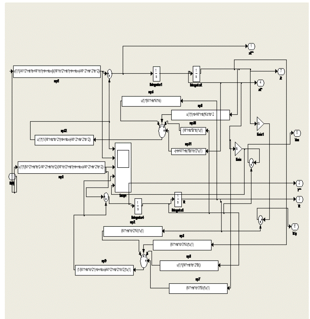
| Where mb=mass of the blade, mt is the equivalent top mass on the tower, N is the number of the blades, mb is the equivalent mass of ablade, rb is the radius of the blade at which the lumped thrust force FT is applied, yt is the fore-aft bending displacement of the tower and ξ is the flapwise angular displacement of the blades. Bt and Bb are the equivalent damping coefficients, and Kt and Kb are the equivalent stiffness coefficients of the tower and a blade, respectively. The relative wind speed is defined as Ve=Vw- y*t - ξ*rb , where Vw denotes the absolute wind speed. The Fig 2 below, shows the Subsystem of Structural model of wind turbine (HAWT). |
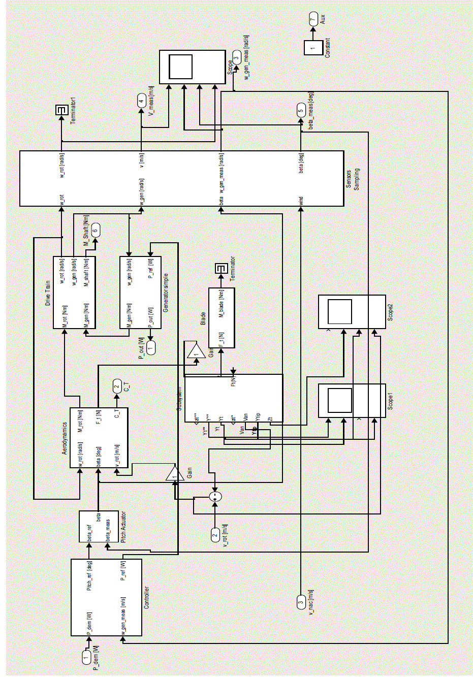
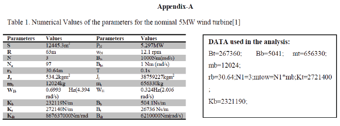
| The simulink model of 5MW HAWT shown in fig. 3 has been constructed using Matlab and parameters with values given in the table.1of appendix A. The results have been obtained for various wind conditions are discussed below |
| a) Wind step from 9m/s to 11m/s. |
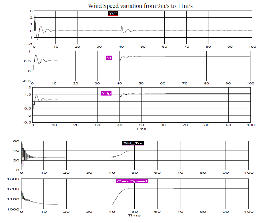
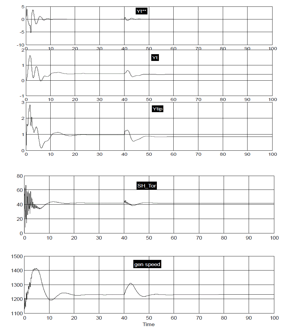
| To obtain simulation results of flap wise displacement of blade of wind turbine speed is taken 9m/s up to first 40ms to 11m/s from 40 ms to 100 ms in comparison to 15m/s to 17m/s step change as in [1] . The wave forms shown below gives the behavior of different physical quantities i.e. torque of the shaft, displacement of tip of the tower (Ytip), speed of generator (r.p.m), acceleration associated with tower displacement (Yt**) and displacement of tip of the tower (Y). |
| From the fig. 4, it is observed that large variations in the shaft torque occurred at 40ms and tower oscillations are small for 9m/s to 11m/s wind step as compared to open-loop response due to wind step from 15m/s to 17m/s for the lumped and FAST codes as in [1].The variations observed from [1] with lumped and FAST codes were obtained for 15m/s to 17m/s wind speed gust as gen_speed(Generator Speed) reduced from 1200 rpm (starting) to approximately 1020 rpm at 40ms and increased to 1300rpm from 40ms to 100ms. Yt**(m/2) isthe fore-aft bending displacement of the tower which remains between the limits -0.5(m/2) to 0.5(m/2) at t=0 and reached to very small variations near zero value after 40ms. The main difference observed with generation speed as it starts with 1200rpm similar to [1] but after 40ms it just rises to 1200rpm as compared to 1300 rpm in [1]. Other parameters are marginally different from results obtained in [1].The equations for acceleration of blade and tower vibrations were derived from the eq.(4) and (5) as given below. |
 (6) (6) |
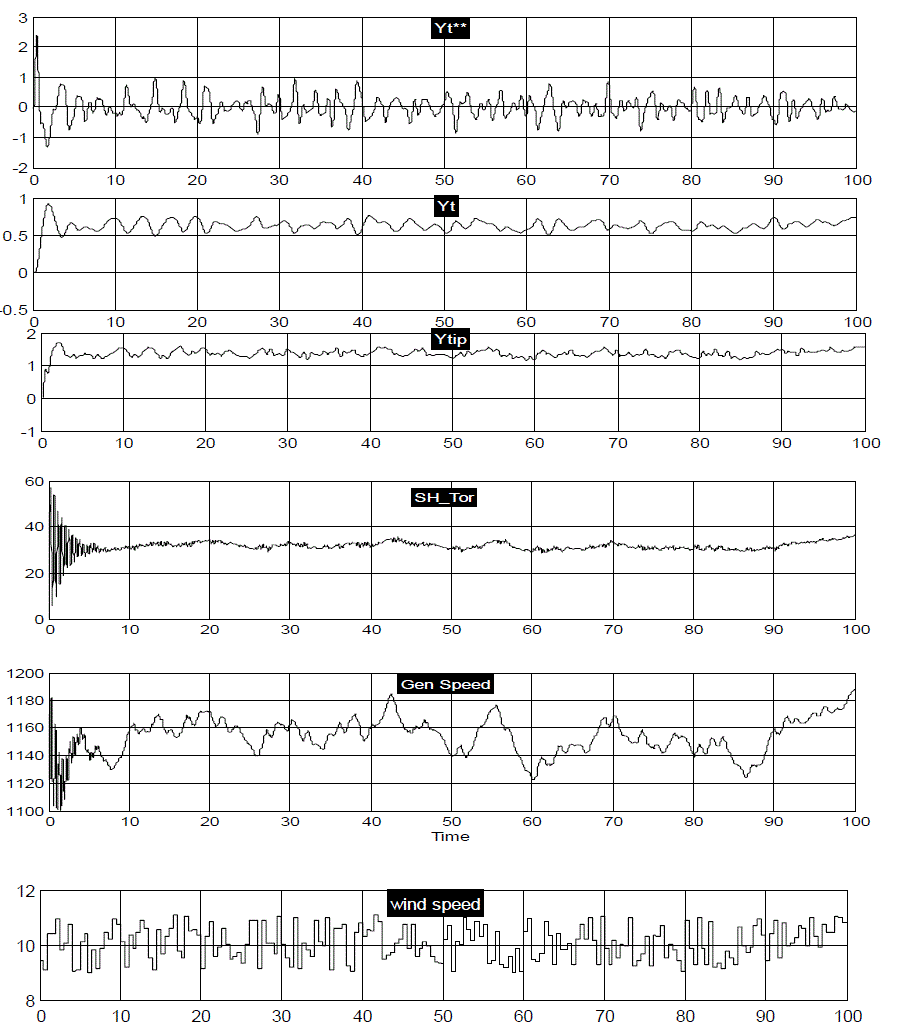
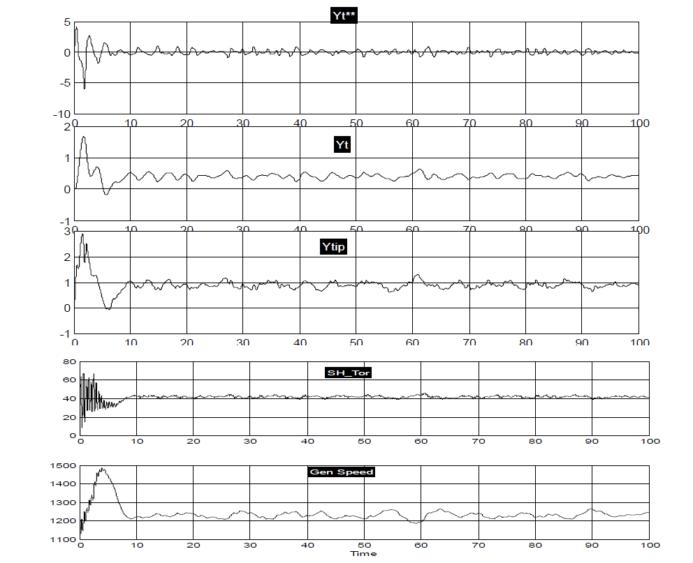
| From the above fig. 5, it is observed that for random wind speed variations with step change of 9m/s to 11m/s the oscillations observed in tower displacement, shaft torque and generator speed were found to be approximately similar as that of the simulation results which were obtained in [1] for wind step 15m/s to 17m/s. The initial speed of generator 1173 r.p.m and pitch angle β0=12° with all other initial conditions were set to be zero. The results obtained by the implemented subsystem are found to be much smoother waveforms for Yt**, Yt, Ytip, Sh_Tor and Gen_Speed as wind speed randomly varies from 09m/s to 11m/s. The main purpose to discuss this wind speed variation is that it would give nearly same results as with 15m/s to 17m/s in [1]. |
| From the above fig. 6, it is observed that for wind speed variations with step change of 15m/s to 17m/s the oscillations observed in tower displacement, shaft torque and generator speed were found to be similar even much small variations were observed as that of [1] for wind step 15m/s to 17m/s. The initial speed of generator 1173 r.p.m and pitch angle β 0=12° with all other initial conditions were set to be zero. The variations observed from [1] with lumped and FAST codes were obtained for 15m/s to 17m/s wind speed gust as gen_speed reduced from 1200 rpm (starting) to approximately 1020 rpm at 40ms and increased to 1300rpm from 40ms to 100ms. Yt**(m/2)the fore-aft bending displacement of the tower remains between the limits -0.5(m/2) to 0.5(m/2) at t=0 and reached to very small variations near zero value after 40ms. But in this analysis with matlabsimulink model Yt**(m/2)the fore-aft bending displacement of the tower remains between the limits -5(m/2) to 5(m/2) at t=0 and almost dies out after 40ms.The main difference observed with generator speed as it starts with 1200rpm similar to [1] but upto 10 ms it rises to 1400 rpm as compared to reduced value of 1020rpm in [1] and at 40ms it just rises to 1300rpm then to 1220rpm at 50ms as compared to remain constant to 1300 rpm in [1]. Other parameters such as shaft torque follows same waveform as that of [1] but the response is much smooth as compared to results obtained with FAST and lumped codes obtained in [1]. |
| D) Random Wind Step 15m/s to 17m/s. |
| From the above fig. 7, it is observed that for wind speed variations with step change of 15m/s to 17m/s the oscillations observed in tower displacement, shaft torque and generator speed were found to be similar even much small variations as observed as that of [1] for wind step 15m/s to 17m/s. The initial speed of generator 1173 r.p.m and pitch angle β0=12° with all other initial conditions were set to be zero.The generator speed obtained in this study obtained to be increased from 1200 rpm to 1500 rpm for random wind speed 15m/s to 17m/s at t=0 to 10 ms. At t=10ms the generator speed stabilized to 1220 rpm with much less variations as compared to variations observed in [1]. |
CONCLUSIONS
|
| The conclusions were drawn in different cases a),b),c) and d) pertaining to different wind conditions. |
| • In case a): From Fig. 4. It is concluded that the oscillations occurred in tower were small for step change in steady wind speed from 9m/s to 11 m/s in comparison to wind step of 15m/s to 17m/s in [1]. |
| • In case b): Fig. 5. Shows that the oscillations occurred in the tower, generator speed, shaft torque and tower acceleration were small corresponds to random wind variations 9m/s to 11m/s as compared to 15m/s to 17m/s speed as in [1]. |
| • In case c): From Fig. 6. It is concluded that oscillations for wind step 15m/s to 17m/s were so small as compared to FAST and Lumped codes in [1]. |
| • In case d): FromFig.7 it has been concluded that for random wind speed step 15m/s to 17m/s the oscillations were found to be so small as compared to [1]. At t=10 ms the generator speed stabilized to 1220 rpm with much less variations as compared to variations observed in [1].Otherwise results obtained were 10 times of [1] if same data of Table 1is used for analysis. |
| |
Figures at a glance
|
 |
 |
 |
 |
| Figure 1 |
Figure 2 |
Figure 3 |
Figure 4 |
| |
 |
 |
 |
| Figure 5 |
Figure 6 |
Figure 7 |
|
| |
References
|
- Farzad A. ,Karolos M. Grigoriadis and Daniel Viassolo “Wind turbine integrated structural and LPV control design for improved closed-loopperformance”International Journal of Control Vol. 85, No. 8, August 2012, pp 1178–1196.
- M.GodoySimoes “Alternative Energy Systems: Design and Analysis with Induction Generators” Taylor and Francis Group, CRC SecondEdition 2008.
- Bianchi,F.D. et.al “Wind Turbine Control Systems Principles, Modelling and Gain Scheduling Design”, London:Springer-Verlag 2007.
- S.Heier “Grid Integration of Wind Energy Conversion Systems” John Wiley & Sons, Ltd. 2006.
- Tomas Petru, TorbjörnThiringer“Modeling of Wind Turbines for Power System Studies” IEEE Transactions on Power Systems , vol. 17, no. 4,pp-1132-1139, november 2002.
|
 |