Keywords
|
| Bridgeless rectifier, Cuk converter, low conduction losses, power factor correction (PFC), PI controller, Brushless dc motor(BLDCM), Voltage Source Inverter(VSI). |
INTRODUCTION
|
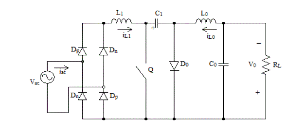
| For power supplies with active power factor correction (PFC) techniques are very essential for many type of electronic equipment to meet harmonic regulations. Most of the PFC rectifiers utilize a boost converter at front end. A conventional PFC technique has lower efficiency because of significant losses in the diode bridge. A conventional PFC Cuk rectifier is shown in fig 1. The current flows through two rectifier bridge diodes and the power switch (Q) during the switch ON-time, and through two rectifier bridge diodes and the output diodes (D0) during the switch OFF- time. |
| During each switching cycle, the current flows through three semiconductor devices. As a result, a significant conduction loss, caused by the forward voltage drop across the bridge diode.In a bridgeless PFC circuits, where the number of semiconductors generating losses will be reduced by eliminating the full bridge input diode rectifier.A bridgeless PFC rectifier allows the current to flow through a minimum number of switching devices compared to the conventional Cuk rectifier.It also reduces the converter conduction losses and which improves the efficiency and reducing the cost. A bridgeless power factor correction rectifier is introduced to improve the rectifier power density and/or to reduce noise emission via soft-switching techniques or coupled magnetic topologies.The Cuk converter has several advantages in power factor correction applications, such as easy implementation of transformer isolation, natural protection against inrush current occurring at start-up or overload current, lower input current ripple, and less electromagnetic interference(EMI) associated with discontinuous conduction mode topology. Thus for applications, which require a low current ripple at the input and output ports of the converter, Cuk converter is efficient. |
| Brushless Direct Current (BLDC) motors are one of the motor types rapidly gaining popularity. BLDC motors are used in industries such as Appliances, Automotive, Aerospace, Consumer, Medical, Industrial Automation Equipment and instrumentation. As the name implies, BLDC motors do not use brushes for commutation; instead, they are electronically commutated. BLDC motors have many advantages over brushed DC motors and induction motors. A few of these are: |
| • Better speed versus torque characteristics |
| • High dynamic response |
| • High efficiency |
| • Long operating life |
| • Noiseless operation |
| • Higher speed ranges |
| In addition, the ratio of torque delivered to the size of the motor is higher, making it useful in applications where space and weight are critical factors. The commutation in a PMBLDCM is accomplished by solid state switches of a three-phase voltage source inverter (VSI). |
BRIDGELESS CUK POWER FACTOR CORRECTION RECTIFIERS
|
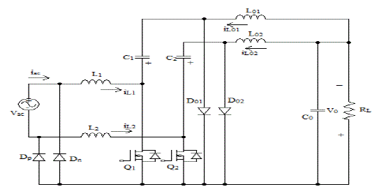
| The bridgeless power factor correction rectifiers are shown in Fig.2. The topology is formed by connecting two DC-DC Cuk converters.Note that there are one or two semiconductors in current flowing path. Hence, the current stresses in the active and passive switches are further reduced and the circuit efficiency is improved compared to the conventional Cuk rectifier. Here, the output voltage bus is always connected to the input AC line through the slow-recovery diodes Dp and Dn. |
| Thebridgelessrectifiers of Fig.2 consists of two semiconductor switches (Q1 and Q2). However, the two semiconductor switches can be driven by the same control circuitry. Compared to conventional Cuk converter topology, the structure of topologies utilizes additional inductor, which is often described as a disadvantage in terms of size and cost.However, a better thermal performance can be achieved with the two inductors compared to a single inductor. |
| It should be mentioned here that the three inductors in the topologies can be coupled on same magnetic core allowing considerable size and cost reduction. Additionally, the “near zero-ripple-current” condition at input or output port of the rectifier can be achieved without compromising performance. |
PRINCIPLE OF OPERATION
|
| Thebridgeless Cuk rectifier of Fig.2 will be considered in this paper. The converter is operating at a steady state in addition to the following assumptions: pure sinusoidal input voltage, ideal lossless components, and all ripples are negligible during the switching period Ts. Here, the output filter capacitor C0 has a large capacitance such that the voltage across it is constant over the entire line period. |
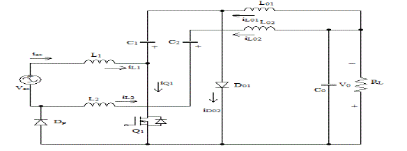
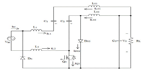
| Note that by refering Fig.3, there are one or two semiconductors in the current flowing path; therefore, the current stresses in the active and passive switches are reduced and the circuit efficiency is improved. During thepositive half-line cycle as shown in Fig 3, the first DC-DC cuk circuit, L1-Q1-C1-L01-D01,is the active through diode Dp,which connects the input AC source to the output.During the negative half-line cycle as shown in Fig.4,the second DC-DC cuk circuit, L2-Q2-C2-L02-D02, is active through diode Dn, which connects the input AC source to the output.The average voltage across capacitor C1 during the line cycle can be expressed as follows: |
 |
| Due to the symmetry of the circuit, it is sufficient to analyze the circuit during the positive half cycle of the input voltage. The operation of the rectifiers of Fig.2 will be explained assuming that the three inductors are operating in DCM. By operating the rectifier in DCM, there are several advantages can be gained. These advantages included natural near-unity power factor, the power switches are turned ON at zero current, and the output diodes are considerably reduced.DCM operation significantly increases the conduction losses due to the increased current stress through circuit components. |
BRIDGELESS CUK CONVERTER WITH AND WITHOUT PI CONTROLLER
|
| The converter without PI controller will not give required constant output voltage whenever some changes or disturbances occur in the input side. Thus the closed loop system can maintain the constant output voltage by comparing the given reference voltage (48V) and the actual output voltage.Here, the PI controller is used in closed loop system. The difference between without and with PI controller is shown in the table 1 and table 2 respectively. |
BRIDGELESS CUK CONVERTER FOR POWER FATOR CORRECTION IN BLDC MOTOR
|
| Power factor correction method is good for ac to dc power conversion in order to reduce the line current harmonics as well as increase the efficiency and capacity of motor drives. Here, a bridgeless Cuk converter is act as PFC converter because of its continuous input and output currents, small output filter, and wide range as compared to other signal switch converters, also it forces the drive to draw sinusoidal ac mains current in phase with its voltage. To generate switching sequence for the VSI feeding the BLDC motor, the rotor position signals, are taken by Hall-effect sensors and therefore, rotor position is required only at the commutation points. The switching sequence for VSI feeding the BLDC motor is shown in table III. |
SIMULATION RESULT AND DISCUSSION
|
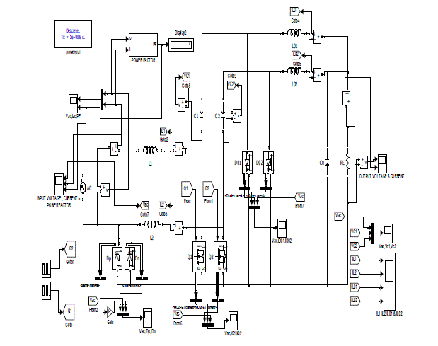
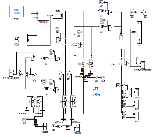
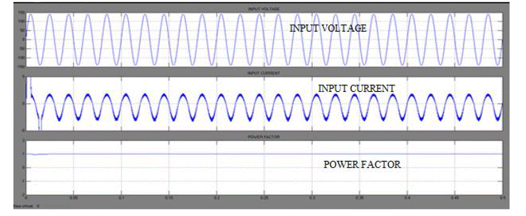
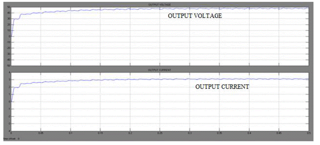
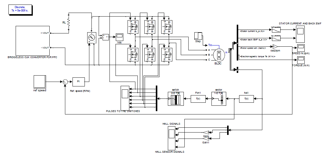
| Fig.6 & Fig.7 shows that simulation of bridgeless cuk converter with and without PI controller respectively with input of 100 Vrms line voltage and output voltage of 48Vdc. Fig.8 shows the input voltage, current and power factor of bridgeless cuk converter with PI controller and Fig.9 shows that the output voltage and current of bridgeless power factor correction with PI controller.Fig.10 shows the simulation diagram of bridgeless cuk converter for power factor correction in BLDC motor by speed controlling using PI controller. |
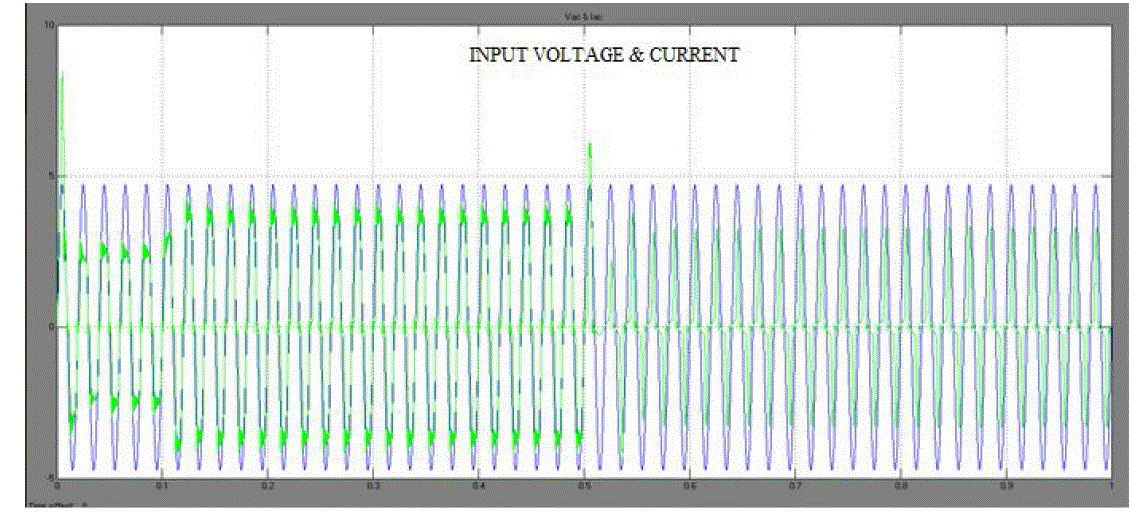
| It is clear from the Fig.8 the input voltage and current are sinusoidal and in-phase. The power factor for the bridgeless cuk converter for power factor correction in BLDC motor is 0.9933.Fig.10 shows the proposed speed control scheme which is based on the control of the dc link voltage reference as an equivalent to the reference speed. However, the rotor position signals acquired by Hall effect sensors are used by an electronic commutator to generate switching sequence for the VSI feeding the PMBLDC motor, and therefore, rotor position is required only at the commutation points. |
| The Fig.11 shows that the input current and voltage is in-phase and sinusoidal by using a bridgeless Cuk converter for power factor correction in BLDC motor. |
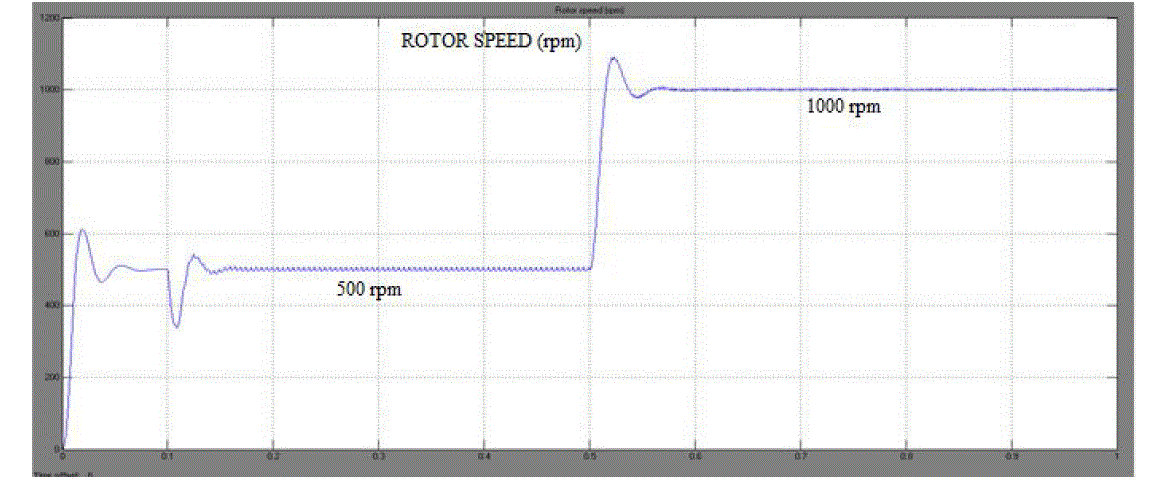
| The Fig.12 shows that the rotor speed of the BLDC motor. From the Fig.12 it is very clear that the speed of the motor is controlled using PI controller. Here from time period 0 to 0.5 sec the speed is controlled and maintained constant speed of 500 rpm and from 0.5 to 1 sec the speed of the motor is controlled to 1000 rpm and maintained constant. |
CONCLUSION
|
| This paper presents Single-phase AC-DC bridgeless rectifierbased on Cuk topologywith and without PI controller. The comparison of single-phase ac-dc bridgeless rectifier based on Cuk topology with and without PI controller is discussed. From the result it is clear the bridgeless Cuk converter with PI controller has constant output voltage. By operating the rectifier in DCM, there are several advantages, which includes natural near-unity power factor. Thus, the losses due to turn- ON switching and the reverse recovery of the output diodes are considerably reduced. The performance of the system was verified in the simulation. In this new single-phase AC-DC bridgeless rectifier based on Cuk topology have a better efficiency and power factor.The proposed cuk converter is designed to reduce the input current stress and to bring almost unity power factor in the input side. The design of bridgeless cuk converter fed BLDC motor drive is also performed and is modelled in Matlab. The speed of the motor drive is varied by changing the dc link voltage of bridgeless Cuk converter. The speed of the BLDC motor is proportional to the dc link voltage; thereby, a smooth speed control is observed while controlling the dc link voltage. The PFC bridgeless Cuk converter has ensured near unity power factor in a wide range of the speed and the input ac voltage. |
| |
Tables at a glance
|
|
|
| |
Figures at a glance
|
 |
 |
 |
 |
 |
| Figure 1 |
Figure 2 |
Figure 3 |
Figure 4 |
Figure 5 |
| |
 |
 |
 |
 |
 |
| Figure 6 |
Figure 7 |
Figure 8 |
Figure 9 |
Figure 10 |
| |
 |
 |
| Figure 11 |
Figure 12 |
|
| |
References
|
- Abbas A. Fardoun, Esam H. Ismail, Ahmad J. Sabzali and Mustafa A.Al-Saffar, “New Efficient Bridgeless Cuk Rectifiers for PFC Applications,” inIEEE trans. Power Electron., vol. 27, No. 7, July 2012.
- B. Lu, R. Brown, and M. Soldano, “Bridgeless PFC implementation using one cycle control technique,” in Proc. IEEE Appl. Power ElectronConf.,Mar. 2005, pp. 812–817.
- Elizabeth Alphonsa Jose, Thomas, “Matlab Simulink model of Cuk PF corrected BLDC motor drive,” IJAREEIE, vol. 2, issue 6, June 2013.
- Pradeep Kumar, P.R.Sharma and Ashok Kumar, “Simulation and design of power factor correction prototype for BLDC motor control,” Europeanscientific journal, vol. 9, no. 12, April 2013.
- A. Sabzali, E. H. Ismail, M. Al-Saffar, and A. Fardoun, “New bridgeless DCM sepic and Cuk PFC rectifiers with low conduction and switchinglosses,” IEEE Trans. Ind. Appl., vol. 47, no. 2, pp. 873–881,Mar./Apr.2011.
- G. Moschopoulos and P. Kain, “A novel single-phase soft-switchedrectifier with unity power factor and minimal component count,” IEEE Trans.Ind. Electron., vol. 51, no. 3, pp. 566–575, Jun. 2004.
- W. Choi, J.Kwon, E. Kim, J. Lee, and B.Kwon, “Bridgeless boost rectifier with low conduction losses and reduced diode reverse-recoveryproblems,”IEEE Trans. Ind. Electron., vol. 54, no. 2, pp. 769–780, Apr.2007.
- E. H. Ismail, “Bridgeless SEPIC rectifier with unity power factor and reduced conduction losses,” IEEE Trans. Ind. Electron., vol. 56, no. 4,pp.1147–1157, Apr. 2009.
- Y.-S. Roh, Y.-J. Moon, J.-C. Gong, and C. Yoo, “Active power factor correction (PFC) circuit with resistor-free zero-current detection,” IEEETrans. Power Electron., vol. 26, no. 2, pp. 630–637, Feb. 2011.
|