Photovoltaic (PV) systems generate a significant amount of electrical energy used around the world. In accordence with high cost and low effienciency, solar panels and arrays should be operated at the maximum power point (MPP). Photovoltaic cells have variable current and voltage characteristics and MPP depends on solar irradiations and ambient temperature. Obtaining maximum power and reaching highest efficiency level in these panels is an important research topic [1], [ 2]. Maximum power poin tracking (MPPT) is developed to capture maximum power level in variable atmospherically conditions [3], [4]. In this study, the behaviour of varied incremental conductance (IC) MPPT algorithm implemented to PV modules. Larger-medium-small fixedstep sizes and variable step size were applied, analyzed under various conditions. In order to compare the step size impressions, all cases were simulated on MATLAB/Simulink platform.
Keywords |
| Boost DC/DC Converter, Maximum power point tracking, Incremental conductance, Photovoltaic
energy conversion. |
INTRODUCTION |
| Recently, studies about PVs have focused on minimizing the costs and maximizing the conversion efficiency. In MPP,
PV arrays generate the electric energy at maximum efficiency and minimum losses. PV cells have variable current and
voltage characteristics and maximum power point depends on solar irradiations and environment temperature. Because
of that a maximum power tracking control should be made rapidly in varied temperature and solar insolation
conditions[5]. In Figure 1, I-V and P-V characteristics of a solar module in the simulations are showed. |
| In this context, a converter based on power electronics was needed so as to track variable voltage and current among
panel and load. It is also important to track this intermediary block where DC/DC converters are used. The triggering
frequency and range of switching mosfet/ıgbt in the converter have a significant part to obtain maximum power value. |
| In conventional PV, energy conversion systems consist of serial and parallel connected solar panel, DC/DC converter
and battery (or DC load) as shown in figure2. |
| In the literature, both converter design and MPPT algorithms have been studied and presented so far. To reach
maximum power point faster, several algorithms such as Perturbation and Observation (P&O) [6], [7], incremental
conductance [8], look-up table [9], [10], current control loop [11] were proposed and applied. |
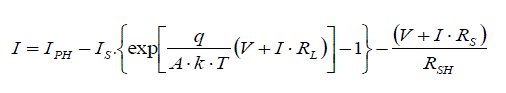
| A photovoltaic cell is basically a PN semiconductor junction diode that converts energy. As the sun light drops on PV
cells, photo-power acts like a forward diode on a large surface. The current expression emerging as a result of the
sunlight hitting on the cell is given in 1. |
 (1) (1) |
| In this expression, photo-current, saturation current, load resistance, series equivalent circuit resistance, parallel
equivalent circuit resistance, terminal voltage, load current, Boltzman’s constant, temperature of PV panel and diode
ideality factor are denoted by IPH, IS, RL, Rs, RSH, V, I, k, T and A respectively. The equivalent circuit diagram for a
solar cell is shown in figure 3[12]. |
| PV module is used in this study has electrical parameters are given in Table 1.In general, PV solar panels reach their
maximum power point at around 25°C. |
| Boost converter, as its name implies, is a structure that boosts the voltage. Its simplified circuit diagram is shown in
figure 4. In PV systems, input voltage defined as Vs is the voltage in the panel while output voltage, defined as V0, is the
battery or load voltage. |
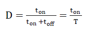
| Mosfet or Igbt is used as switching element. D (duty cycle) is given equation (2), which describes relative conduction
time, equals to switching element conduction time (ton) divided by signal period which is the total conduction and cutoff
time (T = Ton + Toff). |
 (2) (2) |
| The conversion is performed in this converter as follows |
| While switching element (S) turn on, PV structure injects additional energy to inductance through driving current over
inductance (L). Then, switching element is cut off and reverse current force in the inductance charges the capacity
element over the diode. The relationship between output voltage and input voltage is as follows: |
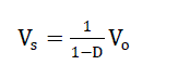 (3) (3) |
 (4) (4) |
| Boost structures are often preferred in stand-alone systems and when panel voltage is lower than battery voltage.
This paper is to examine the various in efficiency, stability and quality of energy conversion for solar systems in
unsteady conditions. Especially, the effects of changeable irradiation over an PV arrays were observed on two
alternative modeled systems in order to determine which case performed better in variable conditions. To do it, two
solar energy conversion systems were experimented. Also, by utilizing MATLAB simulation, the effects MPPT in
photovoltaic energy conversion were assessed. |
TEXT DETECTION |
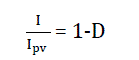
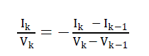
| This algorithm is also called hill climbing.The incremental conductance (IC) algorithm is derived from the PV array
power together respect to voltage and setting the equal to zero. The algorithm is given by the following equation (5). |
 (5) (5) |
| By accouting for the depence of the PV current on the voltage, it is possible to express such a condition as follows
equation (6) [13]. |
 (6) (6) |
| So that the validty of condition (5) is equivalent to follows equation (7). |
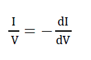 (7) (7) |
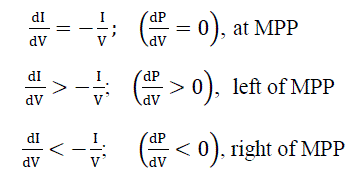
| which means that left-hand side of equation (7) represents the opposite of the PV array’s instantaneous conductance, as
the right-hand side represents its incremental conductance. |
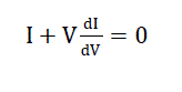
| As a conclusion, the method requires the application of a repeated perturbation of the voltage value, until the next
condition occurs equation(8)[14]. |
 (8) (8) |
| Where the subscript k and k-1 refer to two consecutive samples of the PV voltage and current values.The conventional
algorithm (IC) is shown figure(5) [15]. |
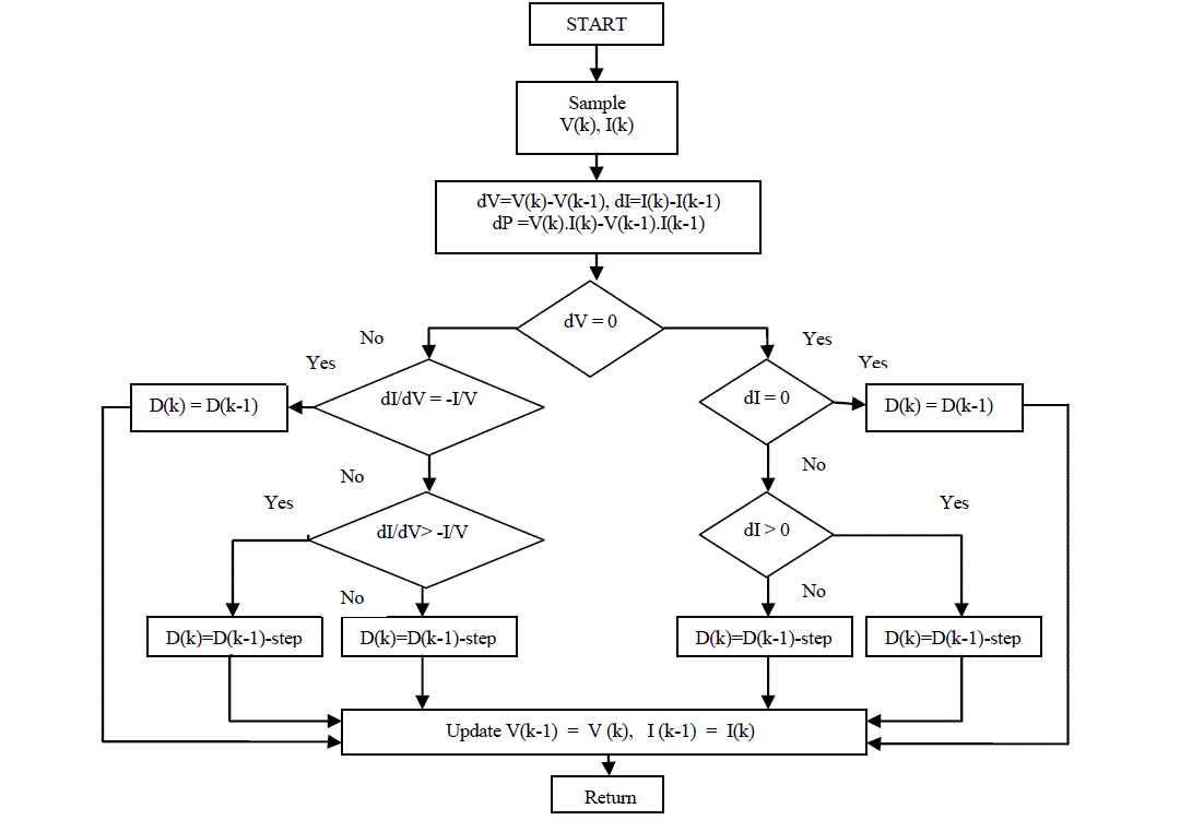 |
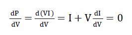
| At the maximum power point, the equations occurs in the following eq. (9a, 9b, 9c). |
 |
| Equation (9a) is repeat of equation (7) for accordance, equation (9b) and (9c) are used to determine the direction where
a perturbation must occur to move the operating point toward the MPP, and the perturbation is repeated until equation
(9a) is pleased. When the maximum power point is reached, the MPPT go on to work at this point up to a change in
current measured. This change in current will correlate to a change in irradiance on the array. The increment step
decide how fast the MPP is tracked. Rapid tracking can be succeed with large increments however, the system may not
work completely at the MPP and ripple around in place of it; because of that there is a trade off. In the variable, instead
of fixed step coefficient used to increase or decrease duty cycle, dI, exhibiting amount of current change, is used in
order to approach maximum power point in parameter to an increase or decrease. |
| In figure (6), MPPT block structure where simulation is performed is shown. MPPT is a power tracking system that
enables to obtain maximum power from PV panels. In MPPT block, DC/DC converter is controlled by IC algorithm
through producing duty cycle. As a result of this, the maximum power level from PV panel is reached. |
RESULTS OF A COMPARISON BETWEEN STEP SIZES |
| The control code duty cycle was written MATLAB inceremental conductanca algorithm code and was tested and run
using MATLAB Function block in MATLAB/Simulink. In simulations, two cases are considered to compare with step
sizes. In first case, outputs of DC/DC converter (DC system) are considered with among larger, medium, small fixed
step sizes when insolation increases. In second one, larger-small fixed sizes and variable step sizes are also considered
when insolation increases and decreases. |
Case I |
| Results obtained from the modeling in MATLAB/SIMULINK are presented in this case. Solar irradiation is around
1000 W/m2 at starting point. Irradiation is increased to about 1040 W/m2 linearly until 0.5 th second. In view of this
change, which can be considered as fast. As can bee seen in figure 7, small step size is 3. 10−3 to obtain less power
value after about 0.15second, but less power ripples occur than medium step size (6. 10−3 ). |
| In figure 8 case, To make clear differences among the fixed step sizes methods: medium step size is increased to
9.10−3 value (large step size) under same conditions. Small step size is to obtain less power with less power ripples.
Hower, In figure 7 and figure 8, medium and large step sizes occurs large power ripples in the PV system. |
| Simulation outcomes were showed, the outcomes were compared to the algorithms with fixed step sizes, if step sizes
decreases as the working point close the maximum power point, but the tracking will be slow. In contrast, if step sizes
increases as the working point away the maximum power point, but the tracking will be fast. |
Case II |
| Incremental conductance algorithm usually uses fixed iteration step size determined by the requirements of the
accuracy at steady state and the response speed of maximum power point [15]. In this case, about differences between
fixed and variable step size methods: Solar insolation is about 1000 W/ m² at starting point it is increased and decreased
to about 1150 W/m² levels. |
| In figure 9 The variable step size, which depends on the changing solar insolation with changing the panel current (ΔI) ,
to faster identfy maximum power point and to obtain more power value from the PV modules. Small fixed step size
take places slower tracking. In addition, it occurs less power ripple. |
| In figure 10, Large fixed step size occurs faster tracking and large power ripples. In both figures, variable step size
shows better performence in the PV system. |
CONCLUSION |
| In this study, Incremental conductance(IC) algorithm-the most used algorithm were applied in MPPT system under
various conditions. The small, medium, large fixed step sizes and variable step size which depends on changing panel
current were applied for comparing. In the step sizes algorithm, Variable step size method has a good advantage in
dealing with minimizing ripples and developing performence in the MPPT algorithm. It is also possible to suggest that
changes in the algorithm will detect no complications in state of hardware, which makes it correct for experimental
objects. |
| |
Tables at a glance |
 |
| Table 1 |
|
| |
Figures at a glance |
 |
 |
 |
 |
 |
| Figure 1 |
Figure 2 |
Figure 3 |
Figure 4 |
Figure 5 |
| |
 |
 |
 |
 |
| Figure 6 |
Figure 7 |
Figure 8 |
Figure 9 |
|
| |
References |
- Panwar S., Saini R.P, Development and simulation of solar photovoltaic model using Matlab/simulink and its parameter extraction .(ICCCE2012) International Conference on Computing and Control Engineering, pp 2-5, 12 - 13 April, 2012.
- Hernanz J.A.R and Campayo J.J, Two photovoltaic cell simulation models in Matlab/Simulink. (IJTPE Journal ISSN 2077-3528) Internationaljournal on “Technical and Physical Problems of Engineering”2012, pp; 45-47.
- Hussein KH., Muta I., Hoshino T., Osakada M., Maximum photovoltaic power tracking: An Algorithm for Rapidly ChangingAtmosphericConditions. Proc. Inst. Elect. Eng. –Gen. Trans. Distrib., 1995; 142; No.1; 59-64.
- Hohm DP.,Ropp ME., Comparative study of maximum point tracking algorithms using an experimental, prorammable, maximum power pointtracking test bed. In: Proc. 28th IEEE Photovoltaic Spec. Conf., 1699-1702, 2000.
- Safari A., Mekhilef. Simulation and hardware implementation of incremental conductance MPPT with direct control method using Cukconverter. IEEE Trans Industrial Electronics ;2011; 58; No 4; 1154-1161.
- Salas V. and et al.2005. Evaluation of a new maximum power point tracker (MPPT) applied to the photovoltaic stand alone systems. SolarEnergy Materials and Solar Cells; 2005; 87 ; pp.807-815.
- Esram T., Chapman PL. Comparison of photovoltaic array maximum power point tracking techniques., IEEE Trans on Energy Conversion;2007; 22; No 2; 439-449.
- Wanzeller M.G., Alves R.N.C., Santos W.A.Current control loop for tracking of maximum power point supplied for photovoltaic array.IEEETr. on Instrumentation and Measurement; 2004; 53; 1304-1310.
- Onat N., Recent Developments in Maximum Power Point Tracking Technologies for Photovoltaic Systems. International Journal ofPhotoenergy. Volume 2010, Article ID 245316, [doi:10.1155/2010/245316].
- Kok S.T., Saad M., Modified Incremental Conductance Algorithm for Photovoltaic System under Partial Shading Conditions and LoadVariation. IEEE Transactions on Industrial Electronics. 2014, Vol.61, No. 10. [doi:10.1109/TIE.2014.2304921].
- Burger, B.; Kranzer, D.; ”Extreme high efficiency PV power converters”, Power Electronics and Applications. EPE’09.13 th EuropeanConference , pp. 1-13, 8-10 september , 2009.
- Özçelik M.A., Yılmaz A.S., Effect of Maximum Power Point Tracking in Photovoltaic Systems and Its Improving and Its Application ofWireless Energy Transmission, 1 st Journal Conference on Clean Energy and Technologies, 2014; Paris/France.
- Mohamed A.E., Zhengming Z., MPPT techniques for photovoltaic applications. Renewable and Sustainable Energy Reviews, 2013,793-813.[doi:10.1016/j.rser.2013.05.022].
- Nicola F., Giovanni P., Giovanni S., Massimo V., Power Electronics and Control Techniques for Maximum Energy Harvesting in PhotovoltaicSystems. International Standard Book Number: 978-1-4665-0690-9, CRC Press. 2013, page: 71-74.
- Abdourraziq M. A., Maaroufi M., A new variable step size INC MPPT method for PV systems. IEEE Multimedia Computing and Systems(ICMCS) International Conference. 2014.
|