This paper presents an investigation into the advantage of polyphase machine over conventional three phase machine. It is also shown by finite-element analyses that, by appropriately defining the pole–arc to pole–pitch ratio, fractional slot winding and selecting proper slot per pole combination the cogging torque can be minimized. The analysis is carried out for a three phase and five phase permanent magnet brushless direct current motor.
Keywords |
| polyphase, cogging torque, finite element, permanent magnet |
INTRODUCTION |
| Permanent magnet (PM) brushless motor drives are increasingly used in ‘more electric’ aircraft systems due to
their high efficiency and high power density . Light weight and small size are the key advantages of such drives over
other competing technologies in aircraft applications ranging from electrical power generation to electromechanical
actuators for flight control and environmental control systems [1]-[2]. |
| In a three phase machine, energy is taken at the rate of 6 pulses for one electrical revolution of the machine
and that in a five phase machine each revolution requires 10 pulses per cycle. Therefore to deliver the same energy in
one revolution a three phase machine require larger magnitude pulses leading to higher torque ripple. It is desirable to
reduce the cogging torque, results from the interaction of permanent magnet magnetomotive force (MMF) harmonics
and air-gap permeance harmonics due to slotting, since it does not contribute to the average torque and may cause
speed ripple and vibration, particularly at light load and low speed. Numerous methods for reducing the cogging torque,
such as skewing the stator slots and/or rotor magnets, shaping the magnets, optimizing the pole–arc to pole–pitch ratio
of the magnets, employing a fractional number of slots per pole, etc., have been proposed. Machines equipped with
interior- magnet rotors generally have a higher torque density due to the saliency torque component and require less
permanent magnet material. They also exhibit a higher demagnetization withstand capability, which is an important
consideration under flux-weakening operation. The power rating of the converter should meet the required level for the
machine and driven load. However, the converter ratings cannot be increased over a certain range due to the limitation
on the power rating of semiconductor devices. One solution to this problem is using multi-level inverter where switches
of reduced rating are employed to develop high power level converters. The advent of inverter fed motor drives also
removed the limits of the number of motor phases. This fact made it possible to design machine with more than three
phases and brought about the increasing investigation and applications of multi-phase motor drives. |
| In order to develop a reliable three phase motor therefore now a day, quadruplex winding is provided which
necessitates requirement of more semiconductor devices and hall sensors and hence demands more complex circuitry.
This short coming of a three phase topology can be resolved by providing a simplex wound fractional slot winding
multiphase winding. The multiphase topology can itself be defined as a reliable and redundant topology. A multi-phase
permanent-magnet (PM) motor exhibits a high fault tolerant capability, as it can be designed to reduce the fault
occurrence as well as to operate indefinitely in the presence of fault. With multi independent phases, in the event of
failure of one or more, the remaining healthy phases let the motor to operate properly [1]-[2]. Multi-phase motor drives
permit a boost in torque by reducing the amplitude and increasing the frequency of torque pulsation, reducing the stator
current per phase without increasing the voltage per phase, increasing the reliability and power density, allowing the
design of very compact high efficiency drives with intrinsic fault-tolerant capabilities [3]. |
COMPARISON BETWEEN THREE PHASE AND FIVE TOPOLOGY |
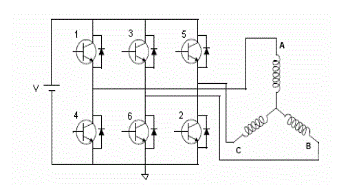
| The PMBLDC motor is fed by a 3-phase inverter as shown in fig.1. Three phase Brushless DC Motor is
operated by means of an electronic six-step commutation system. Six-step commutation is a cost-effective means of
electronic commutation, due to the simple and relatively inexpensive feedback and drive devices. In six-step
commutation, only two out of the three Brushless DC Motor windings are used at a time. Steps are equivalent to 60
electrical degrees, so six steps makes a full, 360 degree rotation. One full 360 degree loop is able to control the current,
due to the fact that there is only one current path. Six-step commutation is typically useful in applications requiring
high speed and commutation frequencies. A six-step Brushless DC Motor usually has lower torque efficiency than a
sine-wave commutated motor. As mentioned, in the control scheme, torque production follows the principle that
current should flow in only two of the three phases at any instant. The stator windings of the motor are energized in
pairs by switching the transistors of the inverter in the sequence as shown in table1, for rotation in a given direction.
The sequence is reversed for rotation in the opposite direction. The table 1 also gives the period of conduction along
with the devices which are conducting during that period. The governing voltage equation of three phase system is: |
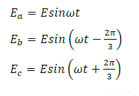 (1) (1) |
| Each semiconductor device will therefore conducts or 120 electrical degrees and the power output by a three phase
motor is 1.5 times greater compared to a single phase motor . Similarly higher number of phases increases the out by
corresponding factor which will be discussed in the paper. |
| In multi-phase machines, by dividing the required power between multiple phases, more than the conventional
three, higher power levels can be obtained and power electronic converters with limited power range can be used to
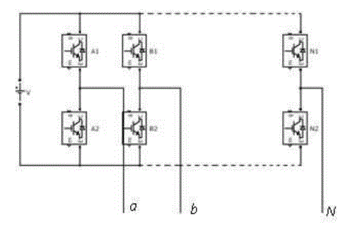
drive the multi-phase machine. The drive for a multiphase topology in general is as shown in fig2, and for a five phase
drive 10 step commutation is require and the commutating sequence is as in Table2.In general for an n-phase motor nphase
subtracted by one phase will be contributing to the output power. Each semi converter device in the five phase
drive will have to conduct for a duration of 144 electrical degrees. The pulsation in the output power is reduced which
increases the motor efficiency. The governing voltage equations for a five phase system are given by: |
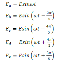 (2) (2) |
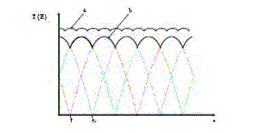
| The average output power torque produced for a three phase and five phase motor shows that the ripple amplitude is
reduced and ripple frequency is increased with more number of phases as shown in Fig3 , show the comparison o
average voltage under different operating conditions. The peak to peak ripple percentage in a three phase system is 15%
whereas it is reduced to 5% in a five phase system. The simulation result will show the reduced ripple in phase voltages
which validate the theory. Selecting the number of phases is also critical according to the applications because of the
circuitry. Increased number of phases increases the complexity of circuit hence increasing the requirement of
semiconductor devices. |
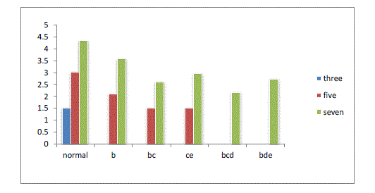
| Fig4 shows the fault tolerant capability as well as the improvement in power by the application of multiphase topology.
A five phase motor can be operated with constant power until two phases gets faulty and for a seven phase topology the
motor can be operated with constant power up to three phases gets faulty. The analysis can be extended to any number
of phases , but such a drive will increase the complexity of the circuit. The constant power mentioned is attained by
exiting the phases with improved current by suitably modeled drive system. Therefore for the same volume and rated
machine, by design algorithm increased power density can be attained by multiphase system. |
DESIGN OF THE MOTOR |
| The specifications of the experimental motor is as in Table 3.The initial design of the BLDC includes the
determination of the main dimensions including stator inner diameter and effective length of the rotor, for the specific
flux density, electric and magnetic loading, and speed, the output power is proportional to rotor volume. |
| The higher the number of poles, the smaller is the stator outer diameter for a given rotor diameter.
Furthermore, from the motor point of view, the copper loss is reduced when increasing the number of poles, because
the end windings become shorter. However, increasing the number of poles will lead to a higher basic switching
frequency and hence an increase in iron losses. This increased loss is however mitigated due to the reduced stator back iron depth and thus reduces to some extent the iron losses. The risk of demagnetization for the PMs also reduces with
the increasing number of poles. From the power converter point of view, a higher switching frequency is required for a
higher number of poles. A pole number of 16 is selected in the design . Selection number of slots mainly depends on
the cogging torque and end copper requirement. If the ratio of slot number to pole number is even, then every edge of
every pole lines up with every slot, causing cogging. If a fractional slot combination is used, fewer pole edges line up
with the slots and hence reduced cogging torque. Here a fractional slot winding is designed to reduce the cogging
torque. |
| In order to calculate the number of turns the motor design equations are used [4]-[5].
In general EMF contributing to the electromagnetic power is |
 (3) (3) |
| where L is the active motor length,Dr is the rotor outer diameter, Nph is the number of phases, Nph-1 is the number of
phases conducting simultaneously, Nt the number of turns per phase, Kw is the winding factor, Bg the air-gap magnetic
flux density and n the rotational speed in rev/s. |
| The general equation for electromagnetic torque is: |
 (4) (4) |
| where, i is the square-wave current amplitude. The equations are solved for three phase and five phase machines. The
electromagnetic power (p0 ) and torque are always positive because negative EMF times with negative current feeding
gives a positive product. The specifications of the selected parameters are shown in Table3 and Table4. |
FINITE ELEMENT ANALYSIS RESULTS |
| By using the finite element analysis (FEA) it is possible to solve the electromagnetic state of the machine. When
the machine geometry is described into the FEA-software, and solved to view the generated back EMF generated. The
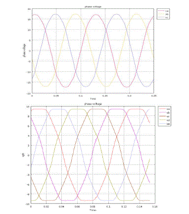
simulation done for three phase and five phase BLDC back EMF waveforms are as shown in Fig5. It can be seen that
the phase voltage amplitude has reduced, ripple amplitude is reduced and ripple frequency has increased with multiple
phases. In analogous to voltage waveform the current waveform can be studied. |
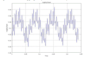
| The simulation is carried out for cogging torque which is produced by interaction of the poles with the stator teeth
when the stator is not excited. Fig6 shows the cogging torque a 60 slots 16 pole motor. |
CONCLUSIONS |
| A three phase and five phase fault-tolerant PM BLDC motor characteristics has been analyzed in the healthy-mode and
faulty-mode operation with the general voltage equations. The analysis has pointed out that a 5-phase motor is able to
run up to rated torque even with one or two phase open, by proper increase of the feeding currents in the healthy
phases. In faulty mode operation of a multiphase system, the average torque is unaffected, while the incoming torque
ripple does not prevent the overall behavior. Also the advantage of fractional slot windings motor in view of cogging
torque is also verified by simulation. |
| |
Tables at a glance |
 |
 |
 |
 |
| Table 1 |
Table 2 |
Table 3 |
Table 4 |
|
| |
Figures at a glance |
 |
 |
 |
| Figure 1 |
Figure 2 |
Figure 3 |
| |
 |
 |
 |
| Figure 4 |
Figure 5 |
Figure 6 |
|
| |
References |
- L. Parsa, H.A. Toliyat, “Fault-Tolerant Five-Phase permanent magnetmotor drives”, Industry Applications Conference, 2004. 39th IAS AnnualMeeting. Conference Record of the 2004 IEEE, Volume 2, 3-7 Oct. 2004 Page(s):1048 - 1054 vol.2
- Mecrow, A. Jack, and J. Haylock, “Fault–Tolerant permanent–magnet machine drives”, IEE Proc., Electr. Power Applications, vol.143, no. 6,pp. 437–442, Dec. 1996.
- Min Dai, Ali Keyhani and Tomy Sebastian, "Torque ripple analysis of a PM Brushless DC motor using Finite Element Method" ,IEEE Transactions on energy conversion, Vol. 19, No. 1, March 2004.
- I.R. Handershot, T.J.E. Miller, “Design of Brushless Permanent Magnet Motors”, Oxford, U.K.: Oxford, 1994
- D. C. Hanselman, Brushless Permanent Magnet Motor Design. New York: McGraw-Hill, 1994
|