Keywords
|
| Frequency control, interleaved Two-stage flyback converter, DC motor, power factor correction(PFC),Total harmonic distortion (THD). |
INTRODUCTION
|
| Nowadays, the use of high-brightness light-emitting diode is increasing in a lot of outdoor lighting applications such as street lights, tunnel lights, and security lights, because of its high luminous efficacy, ease to drive, the absence of a mercury problem and long lifetime and for this a flyback converter is applicable. |
| The PF is required that is higher than 0.9, and the total harmonic content has to meet the IEC61000-3-2 Class C lighting equipment standard.To achieve high efficiency and good PF and THD in wide output power range, this paper proposes a pulse duty cycle pulse frequency modulation (PDPFM) control method for an interleaved Two-stage flyback (ITSF) converter and this overcomes the disadvantages of single stage fly back converter which can be implemented only for low power application, has low power factor, less efficient with high harmonic factor. A shunt DC motor is chosen for high power application which connects the armature and field windings in parallel or shunt with a common D.C. power source.By using critical conduction mode PWM chips with FPGA technique, the output power, THD and power factor is improved [8].The proposed circuit overcomes the limitations of theconventional single-stage PFC flyback with a constant boost inductance at high line while meeting required line-current harmonic specifications at low line [2]. The two output voltages can be controlled with a single pulse width integrated modulator. The double regulation may be sustained over a wide spread of loads [4]. The proposed converter is configured with proper numbers of series and parallel connectedbasic cells in order to fulfill the required output voltage and power levels, respectively. This leads to flexibility in device selection [11]. |
PROPOSED INTERLEAVED TWO-STAGE FLY BACK CONVERTER
|
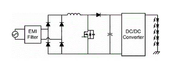
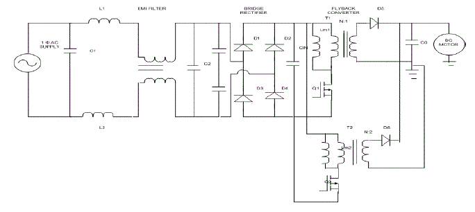
| In the Two-stage structure, the first stage is the ac–dc converter for PFC and the second stage is the dc–dc converter for regulating the output voltage or current. A critical conduction mode (CRM) boost converter is widely used for the first stage and forward, flyback, half- bridge and LLC converters are used for the second stage because they have high PF and efficiency. The two power stages are controlled separately. The proposed control method adopts DCM operation which can achieve high PF for wide output power range and low harmonic distortion. In the proposed method, the interleaved DCM flyback converter is basically controlled by frequency modulation. The flyback converter used here will boost the current and voltage double the time of single stage for overall system performance improvement and which can be used for high power application such as industrial lighting. The load used here is a DC motor for which the speed and torque characteristics are determined and achieving high efficiency. |
Operation Principle
|
| The Electromagnetic interference (EMI, also called radio-frequency interference or RFI when in radio frequency) is disturbance that affects an electrical circuit due to either electromagnetic induction or electromagnetic radiation emitted from an external source. There are Differential mode EMI and Common-mode EMI. |
DESIGN OF EMI FILTER
|
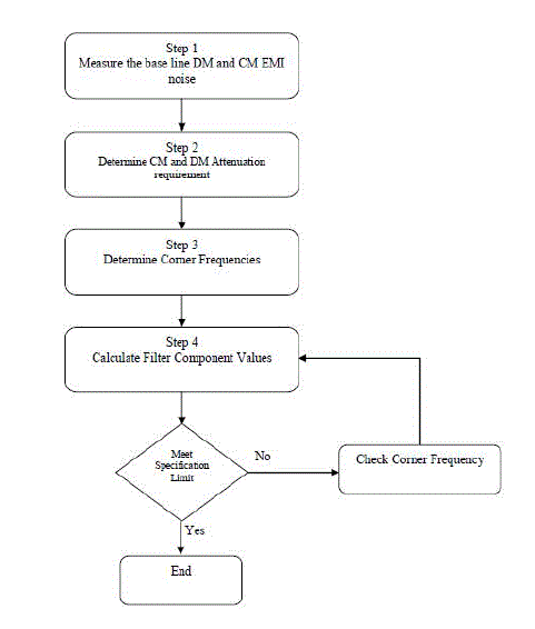
| An EMI filter has to be designed so that the conducted emission of the product can satisfy the relevant regulatory limit. Fig. (4), shows the steps for the proposed filter design procedure. |
| 1. The first step that must be considered in EMI filter design is accurate measurement of the base line (i.e. without filter) common mode EMI noise spectrum, (VCM,measured)dB and differential-mode EMI noise spectrum, (VDM,measured)dB of the device under test by means of the measurement system. |
| 2. The second step is to determine the required CM-noise attenuation (Vreq, CM)dB and DM-noise attenuation (Vreq, DM)dB using the following two equations: |
| (Vreq, CM)dB = (VCM, measured)dB – (Vlimit)dB + CF |
| (Vreq, DM)dB = (VDM, measured)dB – (Vlimit)dB + CF |
| 3. The third step is to determine the minimum corner frequency of second order L-C filter for CM and DM according to the attenuation requirement for all frequency spectrums. |
| 4. The final step in designing is to determine the inductor and capacitor component values (LCM,CCM) and (LDM,CDM) of the conducted EMI filter from the corner frequencies (fR,CM) and(fR,DM). |
FLYBACK CONVERTER
|
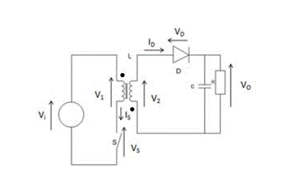
| The flyback converter is used in both AC/DC and DC/DC conversion with galvanic isolation between the input and any outputs. More precisely, the flyback converter is a buck-boost converter with the inductor split to form a transformer, so that the voltage ratios are multiplied with an additional advantage of isolation. When driving for example a plasma lamp or a voltage multiplier the rectifying diode of the boost converter is left out and the device is called a flyback transformer. |
INTERLEAVED TWO-STAGE STRUCTURE OF FLYBACK CONVERTER
|
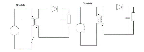
| In the above figures, for theon-state, the energy is transferred from the input voltage source to the transformer (the output capacitor supplies energy to the output load) whereas, in the off-state, the energy is transferred from the transformer to the output load (and the output capacitor). |
SPECIFICATIONS OFINTERLEAVED TWO- STAGE FLYBACK CONVERTER
|
| CRM boost - 387 μH |
| inductance (L) |
| Flyback magnetizing - 1452 μH |
| inductance (Lm1) |
| Turns ratio (Np : Ns) - 49 : 25 |
| Flyback switching - 67 kHz |
| frequency (fsw) |
| The flyback converter is an isolated power converter. The two prevailing control schemes are voltage mode control and current mode control (in the majority of cases current mode control needs to be dominant for stability during operation). Both require a signal related to the output voltage. There are three common ways to generate this voltage. The first is to use an optocoupler on the secondary circuitry to send a signal to the controller. The second is to wind a separate winding on the coil and rely on the cross regulation of the design. The third consists on sampling the voltage amplitude on the primary side, during the discharge, referenced to the standing primary DC voltage.This topology is now replacing ringing choke converters (RCCs) in applications such as mobile phone chargers. |
POWER FACTOR CORRECTION
|
| The flyback topology is an extension of the basic boost topology widely used in power-factor-correcting front-end stages in many power supplies and electronic ballasts. It is therefore possible to obtain a high power factor without adding additional switching stages and inductors simply by operating the circuit from a full-wave rectified voltage without dc bus smoothing and using a similar control approach. |
 |
EFFICIENCY AND POWER LIMITS
|
| The basic flyback converter can provide efficiencies of above 80% at power levels up to about 50 W. LED drivers requiring a high output current often use a two-stage topology comprising a boost front end followed by a flyback output stage. Since the first stage produces a regulated high-voltage dc bus, the design of the flyback second stage can be greatly simplified and optimized for efficiency with only a small output capacitor to remove high-frequency ripple. |
 |
SIMULATION OF THE PROPOSED SYSTEM
|
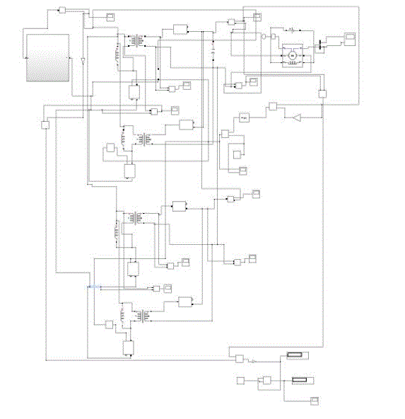
| An input of 230v AC supply is given, a pulsating DC is obtained. The output of two stage voltage and current is boosted to improve the system performance. The method of tuning the parameters is done by PI controller which optimizes the error value. The power factor obtained is high with low harmonic distortion and high efficiency. |
SIMULATION RESULTS
|
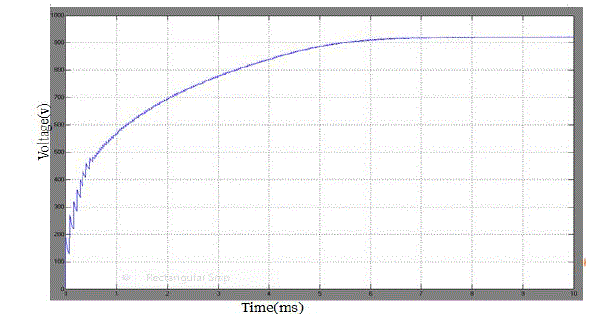
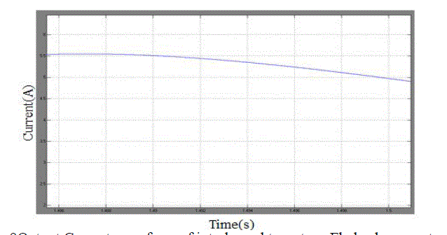
| In the above two figures, the boosted voltage and current waveform is shown. The output voltage of a two stage is 900v.Similarly, in case of current for a large load such as a DC motor is used which generates a current value of about 6A. |
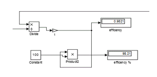
| In the fig 10, the power factor of a two stage process is high (0.98) which is equal to unity. Due to boosted voltage and current, the system will have high frequency response and still the power factor obtained is high. |
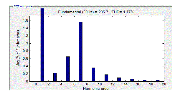
| In the fig 11, Harmonic distortion by FFT analysis for a two stage process is 1.77% which is the required output for a two stage process having low harmonic distortion achieved after the simulation. |
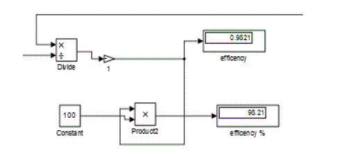
| In the fig 12,the two stage fly back converter shows increase in efficiency of around 98% for a DC motor due to improved system performance. |
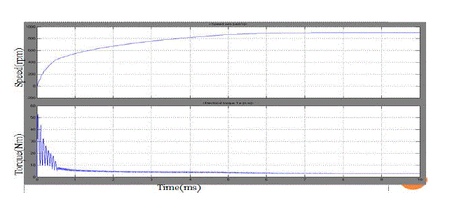
| In the fig 13, the speed and torque characteristics of a DC motor are obtained.The motor has a high starting torque, so the motor torque and current will be same and as speed increases the current decreases. Similarly, when torque decreases the current also decreases. |
CONCLUSION
|
| The proposed control method increases the switching frequency, the turn-ON time and the duty cycle under heavy load with low ac line condition for low rms current and it decreases under light load with high ac line condition for low switching loss. Therefore, the proposed converter has high efficiency for wide input voltage and output load ranges. The results showed that the proposed converter has high efficiency, high PF, and low THD. Therefore, the proposed converter is considerably suitable for wide output range of high power applications. Since this project deals with high power application, these LED’s can be used in car beams and the flyback converter can be applicable where maximum LED lights are used. |
| |
Figures at a glance
|
 |
 |
 |
 |
 |
| Figure 1 |
Figure 2 |
Figure 3 |
Figure 4 |
Figure 5 |
| |
 |
 |
 |
 |
 |
| Figure 6 |
Figure 7 |
Figure 8 |
Figure 9 |
Figure 10 |
| |
 |
 |
 |
| Figure 11 |
Figure 12 |
Figure 13 |
|
| |
References
|
- J. A. Villarejo, J. Sebastian, F. Soto, and E. de Jodar, “Optimizing the design of single-stage power-factor correctors,” IEEE Trans. Ind.Electron.,vol. 54, no. 3, pp. 1472–1482, Jun. 2007.
- L. Huber and M. M. Jovanovic, “Single-stage single-switch input-current shaping technique with reduced switching loss,” IEEE Trans.Power Electron.,vol. 15, no. 4, pp. 681–687, Jul. 2000.
- SangCheol Moon, Gwan-Bon Koo, and Gun-Woo Moon,“A New Control Method of Interleaved Single-Stage Flyback AC–DC Converterfor Outdoor LED Lighting Systems,” IEEE Trans.Power Electron, vol. 28, no. 8, August 2013.
- H. E. Tacca,“Single-switch two-output flyback-forward converter operation,”IEEE Trans. Power Electron.,vol. 13, no. 5, pp. 903–911,Sep.1998.
- J. Zhang, F. C. Lee, and M. M. Jovanovic, “A novel interleaved Discontinuous-current-mode single-stage power-factor-correctiontechnique with universal-line input,” in Proc. IEEE Power Electron. Spec.Conf., 2001, vol. 2, pp. 1007–1012.
- D.Wang, X. He, and J. Shi, “Design and analysis of an interleaved flyback-forward boost converter with thecurrentautobalancecharacteristic,” IEEETrans. Power Electron., vol. 25, no. 2, pp. 489–498, Feb. 2010.
- Y.-C. Hsieh, M.-R.Chen, and H.-L. Cheng, “An interleaved flyback converter featured with zero-voltage transition,” IEEE Trans. PowerElectron.,vol. 26, no. 1, pp. 79–84, Jan. 2011.
- K. I. Hwu and Y. T. Yau, “An interleaved AC-DC converter based on current tracking,” IEEE Trans. Ind. Electron., vol. 56, no. 5, pp.1456–1463, May 2009.
- W. Wang, X. Zhang, and D. Xu, “Novel interleaved single-stage AC/DC Converter with a high power factor and high efficiency,” J.Power Electron.,vol.11, no. 3, pp. 245–255, May 2011.
- S. Park, Y. Park, S. Choi, W. Choi, and K. B. Lee,“Soft-switched interleaved boost converters for high step-up and high-power applications,”IEEE Trans. Power Electron., vol. 26, no. 10, pp. 2906–2914, Oct. 2011.
|