Keywords
|
| Adaptive control, distributed generation (DG), grid connection, stand-alone power supply, total sliding mode control (TSMC). |
INTRODUCTION
|
| In order to protect the natural environment on the Earth, the development of clean energy without pollution has a major representative role. The problems with energy supply and use are related to environmental concerns such as air pollution, acid precipitation, ozone depletion, forest destruction, and radioactive substance emissions. To prevent these effects, some potential solutions have evolved including energy conservation through improved energy efficiency, a reduction in fossil fuel use and an increase in environmentally friendly energy supply. Energy generated from clean, efficient and environmentally-friendly sources including fuel cell, photovoltaic, and wind energy, have been widely applied for distributed generation (DG) installations. However, the DG units often cannot directly support the electrical appliances with the same power qualities of the grid in terms of frequency and amplitude. There arises the need for a high-performance inverter with the abilities of both stand-alone operation and utility grid connection to ensure efficient utilization of DG units [1]. DG systems commonly need dc–ac converters or inverters as interfaces between their single-phase loads and sources. The basic mechanism of a PWM inverter is to convert the dc voltage to a sinusoidal ac output through the inverter-LC filter blocks. The performance is evaluated by the total harmonic distortion (THD), the transient response, and the efficiency. Thus, much attention has been paid to the closed-loop regulation of PWM inverters to achieve good dynamic response under different types of load. Synchronization issues are predominant when the PWM inverter is connected to the grid. For achieving a higher power factor in the grid connection, digital PLL can be used. Sliding Mode Control is one of the effective nonlinear robust control approaches since it provides system dynamics with an invariance property to uncertainties once the system dynamics are controlled in the sliding mode. The insensitivity of the controlled system to uncertainties exists in the sliding mode, but not during the reaching phase, i.e., the system dynamic in the reaching phase is still influenced by uncertainties. Recently, some researchers have adopted the idea of total SMC (TSMC) to get a sliding motion through the entire state trajectory, i.e., no reaching phase exists in the control process, so that the controlled system through the whole control process is not influenced by uncertainties. This paper attempts to extend the Adaptive TSMC (ATSMC) methods to voltage and current control of a single PWM inverter [3]. |
| This paper is organized into five sections. Following the introduction, the system description of a high performance inverter are described in section II. In section III, the control based on ATSMC methods are developed for the stand-alone and grid-connected power supply modes respectively. In addition, simulation analysis are performed to demonstrate the efficiency and applicability of the developed methodologies in Section IV. Finally, some conclusions are drawn in Section V. |
SYSTEM DESCRIPTION
|
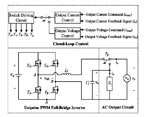
| Fig. 1 shows the proposed high-performance inverter scheme, including a unipolar PWM full-bridge inverter, an ac output circuit, and a closed-loop control method. The PWM inverter framework includes four power switches (TA+ TA-, TB+, and TB-) and a low-pass filter (Lf and Cf ). Moreover, ZL represents an output load in the stand-alone power supply mode, and vu denotes the utility voltage in the grid connected power supply mode. The switch Tg in Fig. 1 is designed to transfer different power-supply modes. In general, the inverter is working in the grid connected power supply mode to transmit the power of DG units into the power grid. When a fault on the utility is detected, the inverter is disconnected from the power grid by changing the switch Tg to supply the power of DG units for specific standalone loads, e.g., emergency electrical equipment with sustainable power capacity. If the utility power recovers, the proposed inverter is operated at the grid connected power supply mode again. All loads are supplied by the utility power if it is available. According to the change of control modes, the closed-loop control method can manipulate the output current (i0) with a high power factor in the grid connected power supply mode or control the output voltage (v0) with a low THD in the stand-alone power supply mode[3]. |
PWM INVERTER CONTROL
|
| A. ATSMC for Stand-Alone Power Supply Mode |
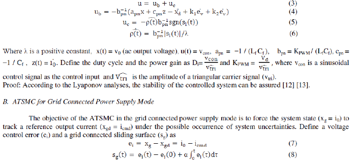
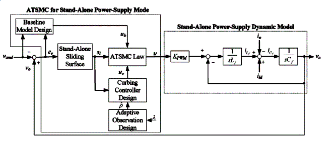
| The objective of the ATSMC in the stand-alone power supply mode is to force the system state (x = v0) to track a reference output voltage (xd = vcmd) under the possible occurrence of system uncertainties. Define a voltage control error (ev) and a stand-alone sliding surface (sl) as |
 (1) (1) |
 (2) (2) |
 |
| bound of the lumped uncertainty to alleviate the chattering phenomenon caused by the inappropriate selection of a conservative constant control gain in the curbing controller. The entire control methodologies of the ATSMC system are summarized in the following theorem [9] [3]. |
| Theorem 1: If the PWM inverter scheme is controlled by the three part ATSMC system described by eqn (3) – eqn (5) with the adaptive observation design shown in eqn (6), then the stability of the ATSMC system for the voltage control of the PWM inverter can be guaranteed. |
 |
| ei(0) is the initial value of ei(t) and α is a positive constant. |
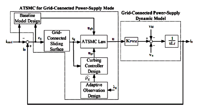
| The proposed ATSMC system for the grid connected power supply mode, as shown in Fig. 3, can be divided into three main parts. The first part addresses the performance design. The objective is to specify the desired performance in terms of the nominal model, and it is referred to as the baseline model design (ugb). Following the baseline model design, the second part is the curbing controller design (ugc) to totally eliminate the unpredictable perturbation effect from the parameter variations and external disturbance so that the baseline model design performance can be assured. Finally, the third part is the adaptive observation design ( pg? ) to estimate the upper bound of the current lumped uncertainty to alleviate the chattering phenomenon caused by the inappropriate selection of a conservative constant control gain in the curbing controller. The entire control methodology of the ATSMC system is summarized Theorem 2. |
| Theorem 2: If the PWM inverter scheme is controlled by the three part ATSMC system described by eqn (9) – eqn (11) with the adaptive observation design shown in eqn (12), then the stability of the ATSMC system for the current control of the PWM inverter can be guaranteed[11]. |
 |
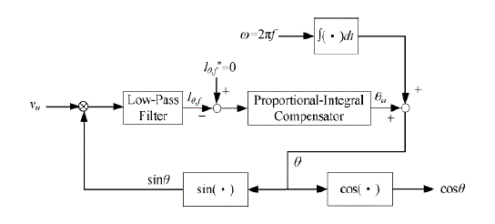
| C. Digital PLL Control |
 |
| Where θa is the compensation angle generated by a proportional – integral (PI) compensator, is the predetermined angular velocity of the utility power and θ0 is the predetermined initial phase angle. |
| By passing through a low pass filter, the signal (lθ,f) with only dc components can be expressed by the definitions of the estimated phase angle θc = θ0 + θa and the phase angle error θe = θu,0 - θc , where θu,0 is the phase angle of the utility voltage vu. The PI compensator produce the compensation phase angle which will gradually force the phase angle error to converge to zero. It means that the phase angle of the utility voltage can be obtained to compute the unit grid connected current command (iucmd). According to Theorem 2, the ATSMC system with the adaptive observation in can guarantee the stable current control of the inverter in the grid connected power supply mode, i.e., the current control error will converge to zero. Since the reference current command (icmd) with cosine waveform is produced by the digital PLL control, the THD within the grid connected current can be controlled in the grid connected power supply mode, even when the grid is noticeably distorted [11][13]. |
| The detailed processes of the transfer between the stand-alone and grid connected power supply modes are summarized as follows. |
| 1. Grid connected power supply mode to stand-alone power supply mode. |
| • Detect a fault on the utility. |
| • Sample the utility voltage and frequency |
| • Check for under/over voltage (OUV) and under/over frequency (OUF). |
| • If there are OUV and OUF, then open Tg, inorder to transfer to stand-alone mode. |
| • Implement ATSMC for stand-alone power supply mode. |
| 2. Stand-alone power supply mode to grid connected power supply mode. |
| • Detect that the grid is operating in nominal condition. |
| • Adjust the reference grid connected current (icmd) to match the frequency and phase of the grid voltage |
| • Close Tg, inorder to transfer back to grid connected mode. |
| • Implement ATSMC for grid connected power supply mode. |
SIMULATION RESULTS
|
| The performance of the proposed control strategy was evaluated by computer simulation using MATLAB / Simulink power system toolbox |
| A. Stand-Alone Power Supply Mode |
| The ATSMC provides triggering pulses for the switches in the PWM inverter. DC battery provides the constant DC voltage for the proposed inverter. In the unipolar PWM full- bridge inverter, an insulated-gate bipolar transistor module including four power switches is adopted, and a low-pass filter with the values of Lf = 80 mH and Cf = 50 μF is selected by considering the switching frequency and the output fundamental frequency. In this paper, the dc bus voltage (Vd) is set at 360 Vdc , and the reference ac output voltage (vcmd) is set at 220 Vrms at 50 Hz in the stand-alone power-supply mode. The parameters for the ATSMC system in the stand-alone power supply mode are chosen to achieve the best control performance by considering the requirement of stability as follows: |
| k1 = 7.2, k2 = 0.3, = 0.5 |
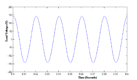
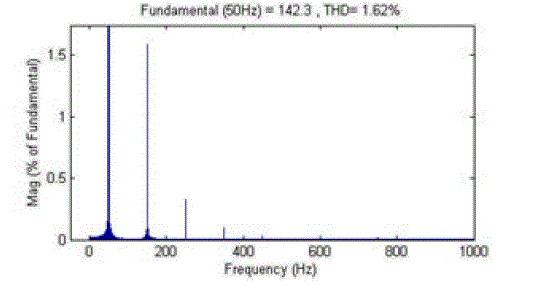
| The experimental voltage response of the stand-alone power supply mode with the proposed ATSMC under the nonlinear load composed of a rectifier with a resistor (500 Ω) inductor (500 μH) capacitor (500 μF) (RLC) load is shown in Fig. 5. From FFT analysis as shown in Fig. 6, the THD within the output voltage can be constricted inside 2% to maintain low output voltage harmonic, even under the nonlinear load condition. The proposed ATSMC can provide over 29.5% THD reduction than the proportional resonant voltage controller under the occurrence of dc bus voltage variations. Moreover, the proportional integral voltage controller usually need manual retuning before being transferred to the process under different operation conditions and uncertainties in practical applications [3]. |
| B. Grid Connected Power Supply Mode |
| The parameters for the ATSMC system in the grid connected power supply mode are chosen to achieve the best control performance by considering the requirement of stability as follows: |
| α = 13, λg = 0.5 |
| Referring to the sliding surface in eqn (8), the parameter α is decided by the convergent time of the current control error at the nominal system. The positive constant λg in eqn (12) can be determined according to the adaptation speed. |
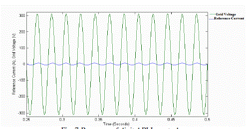
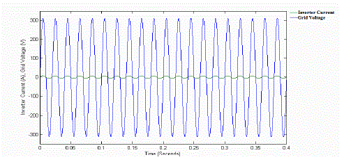
| Fig. 7 shows the experimental response of the digital PLL control scheme, where icmd denotes the grid connected current command. As can be seen from Fig. 7, one can obtain that the grid connected current command can be quickly controlled in phase with the utility voltage (vu) inside 50 ms. This performance is helpful to achieve the objective of unity power factor in the grid connected power supply mode. The experimental voltage and current responses of the grid connected power supply mode with the proposed ATSMC are shown in Fig. 8. As the inverter current is synchronized with the utility voltage, the grid-connected power factor is measured to be 99%. |
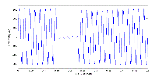
| The PWM inverter is designed for 1 KW. In grid connected mode, a 5 KW resistive load is connected between the grid and the inverter. Therefore the load is served by both utility grid and the inverter. Normally the PWM inverter operates in grid connected mode, then the ATSMC is in current control mode and provide triggering pulses to the switches in the PWM inverter. If there is any fault in the utility grid then a trip command given to the transfer switch and change the inverter to stand-alone power supply mode. At the same time, the ATSMC changes to voltage control mode to provide switching pulses to the PWM inverter. The fault condition is detected by an intentional islanding detection algorithm. Fig. 9 shows the load voltage waveform in both modes. |
| During the fault condition the load is supplied by the PWM inverter with the DC battery in stand-alone power supply mode. The ATSMC controls the output voltage of the inverter with a low THD. The PWM inverter maintains the magnitude of the load voltage at 220 V as same as that of grid connected mode. If the fault is cleared and the utility power recovers, then the transfer switch closes and the PWM inverter is operated in grid connected power supply mode again. Then the load is supplied by both the inverter and utility grid. According to the change of power supply modes, the ATSMC can manipulate the inverter current with a high power factor in grid connected power supply mode. Some research works have investigated that the grid connected power factor is measured to be 97%, and the THD within the grid connected current is about 12.5% for a PWM inverter with a conventional PI current controller in the grid connected power supply mode. Although this degenerated grid connected response can be improved by adjusting the control gains in the PI current controller, it will result in redundant human effort and time in the gain tuning of the PI current controller [3]. So the inverter with the ATSMC indeed yields better grid connected performance with a higher power factor and smaller THD values. |
CONCLUSION
|
| Renewable energy sources like solar, wind and micro-hydro power can be interfaced through the distributed power generation modules with the micro-grid system, which can operate in islanded mode and grid-connected mode. The modeling, control and simulation study of a Distributed Generation inverter developed using MATLAB / Simulink was presented in this paper. Stable control strategies were designed for a single PWM inverter addressing the issues of both stand-alone and grid connected power supply modes. An Adaptive Total Sliding Mode Controller was used for voltage and current control of the single phase inverter in stand-alone and grid connected power supply mode` respectively. This lead to the minimization of THD in the output voltage and the improvement of power factor of the output current of the inverter. Hence, the PWM inverter has been used to provide high power quality ac output through the proposed control technique. Robust control performance, high stand-alone power supply quality, high grid connected power supply quality and automatic transformation between the stand-alone and grid connected power supply modes are the advantages of the DG inverter with the ATSMC scheme. The simulation results obtained using the MATLAB/SIMULINK software environment were incorporated to verify the effectiveness of the proposed system. |
| |
Figures at a glance
|
 |
 |
 |
 |
 |
| Figure 1 |
Figure 2 |
Figure 3 |
Figure 4 |
Figure 5 |
| |
 |
 |
 |
 |
| Figure 6 |
Figure 7 |
Figure 8 |
Figure 9 |
|
| |
References
|
- S. Al-Hallaj, “More than Enviro-friendly: Renewable Energy is also Good for the Bottom Line”, IEEE Power Energy Magazine, Vol. 2, No. 3,May/June 2004.
- Y. Xue, L. Chang, S. B. Kjaer, J. Bordonau, and T. Shimizu, “Topologies of Single-Phase Inverters for Small Distributed Power Generators: AnOverview”, IEEE Transactions Power Electron, Vol. 19, No. 5, September 2004.
- Rong-Jong Wai, Chih-Ying Lin, Yu-Chih Huang and Yung-Ruei Chang, “Design of High-Performance Stand-Alone and Grid-Connected Inverterfor Distributed Generation Applications”, IEEE Transactions on Industrial Electronics, Vol. 60, No. 4, April 2013.
- R. J. Wai, W. H. Wang and C. Y. Lin, “High-performance stand-alone photovoltaic generation system", IEEE Transactions on IndustrialElectronics, Vol. 55, No. 1, January 2008.
- D. C. Lee and G. M. Lee, “Linear control of inverter output voltage in overmodulation”, IEEE Transactions on Industrial Electronics, Vol. 44,No. 4, August 1997.
- I. S. Kim and M. J. Youn, “Variable-structure observer for solar-array current estimation in a photovoltaic power-generation system”,Proceedings, Electrical Power Applications, Vol. 152, No. 4, July 2005.
- K. David Young, Vadim I. Utkin and UmitOzgner, “A Control Engineers Guide to Sliding Mode Control”, IEEE Transactions on ControlSystems Technology, Vol. 7, No. 3, May 1999.
- Debashis Das and Shishir Kumar Pradhan, “Modeling and Simulation of PV Array with Boost Converter: An Open Loop Study”, Thesis Report,2011.
- F. Plestan, Y. Shtessel, V. Bregeault and A. Poznyak, “New Methodologies for Adaptive Sliding Mode Control”, International Journal ofControl, February 2010.
- Rong Jong Wai and Wen Hung Wang, “Grid Connected Photovoltaic Generation System”, IEEE Transactions on Circuits and Systems, Vol.55, No. 3, April 2008.
- Rong Jong Wai and Wen Hung Wang, “Design of Grid Connected Photovoltaic Generation System With High Step Converter and SlidingMode Inverter Control”, IEEE International Conference on Control Applications, Vol. 50, No. 4, October 2007.
- RongJongWai and Kuo Min Lin, “Robust Decoupled Control of Direct Field Oriented Induction Motor Drive”, IEEE Transactions onIndustrial Electronics, Vol.52 No.3, June 2005.
- R. J. Wai, “Adaptive Sliding Mode Control for Induction Servomotor Drive”, IEE Proceedings Electrical Power Applications, Vol. 147 No. 6,November 2000
- Z. Yao, L. Xiao and Y. Yan, “Seamless Transfer of Single Phase Grid Interactive Inverters Between Grid Connected and Stand-alone Modes”,IEEE Transactions on Power Electronics, Vol. 25, No. 6, June 2010.
|