Keywords
|
| Vehicular ad hoc Network (VANET), Roadside units (RSU), Distributed hash table (DHT), Dedicated short communication (DSR), Capacity Maximization Placement (CMP). |
INTRODUCTION
|
| A Vehicular Ad-Hoc Network or VANET is a technology that uses moving cars as nodes in a network to create a mobile network. VANET turns every participating car into a wireless router or node, allowing cars approximately 100 to 300 meter of each other to connect and, in turn, create a network with a wide range. |
| As cars fall out of the signal range and drop out of the network, other cars can join in, connecting vehicles to one another so that a mobile Internet is created. It is estimated that the first systems that will integrate this technology are police and fire vehicles to communicate with each other for safety purposes. The improvement of the network technologies has provided the use of them in several different fields. One of the most emergent applications of them is the development of the Vehicular Ad-hoc Networks (VANETs), one special kind of Mobile Ad-hoc Networks (MANETs) in which the communications are among the nearby vehicles. |
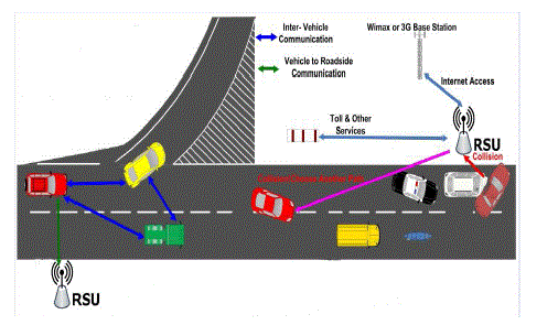
| VANETs are composed for a set of communicating vehicles equipped with wireless network devices that are able to interconnect each other without any pre-existing infrastructure (ad-hoc mode). We propose to utilize RSUs to route packets to distant locations. A vehicle S requesting to send a packet P to a distant vehicle D can send P to its nearest RSU (R1), which, in turn, sends P to the nearest RSU to D (R2) through the RSU network. R2 then sends P to D through multihop. We call our approach Carry and forwArd mechanisms for Dependable mEssage deLIvery in VanEts using Rsus (CAN DELIVER). The design of our system is divided into two basic parts: the first part governs routing from a vehicle to its nearest RSU, and the second part handles routing from RSUs to vehicles. |
PROPOSED CONCEPT
|
A) Motivation of the work
|
| The basic motivation behind using RSUs to route packets is that RSUs are a fixed infrastructure. It is much easier to a packet to a fixed target than to a remote moving object. In addition, the delay of sending the packet through the fixed RSU network is much less than through the VANET. We call our approach Carry and forward mechaNisms for Dependable mEssage deLIvery in VanEts using Rsus (CAN DELIVER). The design of our system is divided into two basic parts: the first part governs routing from a vehicle to its nearest RSU, and the second part handles routing from RSUs to vehicles. Determining an efficient yet cost-effective RSU placement is a key issue for vehicular networks. The simplest RSU placement strategy is uniform distribution, namely, RSUs are spaced apart at a fixed distance. While simple, this placement strategy leads to intermittent disconnection. We tackle the RSU placement problem one highway-like roadway. In this problem, each vehicle can access RSUs in two ways: i) direct delivery, which occurs when the vehicle enters the transmission of each RSU, and ii) multi-hop relaying, which takes place when the vehicle is out of RSU’s transmission range. We account for both access patterns in our placement strategy and formulate this placement problem via an Integer Linear Programming (ILP) model such that the aggregate throughput in the network can be maximized. |
B) Routing From a Vehicle to its Nearest RSU
|
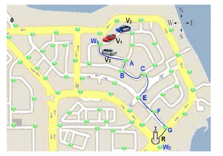
| When a vehicle S wants to send a packet P to an RSU R, it examines whether R is within its transmission range (r). If so, S sends P directly through the wireless channel. Else, S depends on other vehicles to carry P to R. First, S uses its digital map to calculate the shortest road path between its current location and the location of R. To reduce the computing complexity, and since the map is usually fixed, we propose that the shortest path between any two intersections can be calculated and stored so that vehicles use them when sending packets. Hence, we propose to deploy a virtual waypoint at each intersection. In addition, when the distance between two consecutive intersections is greater than r, it is divided into segments slightly less than r, and a waypoint is placed at the end of each segment. Fig. 2 shows an example of a map with waypoints. Each vehicle stores a list Lw that consists of three fields: Source Waypoint, Destination Waypoint, Shortest Path. Lw contains the shortest path between any two waypoints on the map. For example, in Fig. 1, if the “Source Waypoint” is (WS) and the “Destination Waypoint” is (WD), then the shortest path will be (WS,A,B,C,E,F,G,WD). |
| When a vehicle S needs to send a packet, it calculates using the digital map the nearest waypoint to its location, which will be the “Source Waypoint,” and the nearest waypoint to the destination location, which will be the “Destination waypoint.” Hence, S will send the packet to neighbors that are nearest to the “Destination Waypoint.” For example, in Fig. 1,2 vehicle V1wants to send a packet to RSU R. It obtains from its Lw the shortest path from its location to R, which consists of the waypoints {WS, A, B, C, E, F, G, and WD}, and calculates the distance from its current position to R as the sum of individual distances between consecutive waypoints that constitute the shortest path plus (or minus) the distance between its current location and the first waypoint. In Fig. 1, the distance between V1and R will be calculated by V1as {WSA + AB + BC + CE + EF + FG + GWD}+ V1WS. |
C) Routing Protocols
|
| DSDV requires that each node maintain two tables. The bulk of the complexity in DSDV is generating and maintaining these tables. The updates are transmitted to neighbors periodically or scheduled as needed. As growing of mobility and number of nodes in the network, the size of the bandwidth and the routing tables required to update these tables grows simultaneously. The overhead for maintaining and updating these tables will increase correspondingly. It is natural that heavy routing overhead will degrade the performance of the network. |
| Simulation results in shows that DSDV fails to converge if nodes don’t pause for at least 300 seconds during movement; the packet delivery ratio is in the range of 70%-92% at higher rate of mobility; packet loss is mainly caused by stale routing entries; in periodic updates transmission, routing overhead is constant with respect to the mobility rate; nearly optimal path can be selected in routing procedure. Another simulation was done in [5] under the condition of 1000m X 1000m rectangular movement region, 350m constant radio range for each mobile node, 0.4-0.6 m/sec for low mobility, 3.5-4.5 m/sec for high mobility, 512 bytes for the packets length, 1-10 connections/node, and 30 mobile nodes. |
| From the result in Table 1 we can see that the end-to end delay and the routing load increase with the mobility; but the routing load decreases with the number of connections of each node at same mobility. |
DHT IMPLEMENTATIONS
|
| Most notable differences encountered in practical instances of DHT implementations include at least the following: |
| • The address space is a parameter of DHT. Several real world DHTs use 128-bit or 160-bit key space |
| • Some real-world DHTs use hash functions other than SHA-1. |
| • In the real world the key could be a hash of a file's content rather than a hash of a file's name to provide content-addressable storage, so that renaming of the file does not prevent users from finding it. |
| • Some DHTs may also publish objects of different types. For example, key k could be the node ID and associated data could describe how to contact this node. This allows publication-of-presence information and often used in IM applications, etc. In the simplest case ID, is just a random number that is directly used as key K, (so in a 160-bit DHT ID will be a 160-bit number, usually randomly chosen). In some DHTs, publishing of nodes IDs is also used to optimize DHT operations. |
| • Redundancy can be added to improve reliability. The(k, data) key pair can be stored in more than one node corresponding to the key. Usually, rather than selecting just one node, real world DHT algorithms select i suitable nodes, with being an implementationspecific parameter of the DHT. In some DHT designs, nodes agree to handle a certain key space range, the size of which may be chosen dynamically, rather than hard-coded. |
| Some advanced DHTs like Kademlia perform iterative lookups through the DHT first in order to select a set of suitable nodes and send put(k,data) messages only to those nodes, thus drastically reducing useless traffic, since published messages are only sent to nodes that seem suitable for storing the key ; and iterative lookups cover just a small set of nodes rather than the entire DHT, reducing useless forwarding. In such DHTs, forwarding of put(k,data) messages may only occur as part of a self-healing algorithm: if a target node receives a put(k,data) message, but believes that k is out of its handled range and a closer node (in terms of DHT key space) is known, the message is forwarded to that node. Otherwise, data are indexed locally. This leads to a somewhat self-balancing DHT behavior. Of course, such an algorithm requires nodes to publish their presence data in the DHT so the iterative lookups can be performed. |
| A) Requirements |
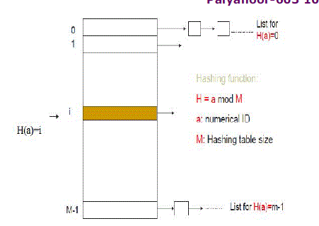
| • Data should be identified using unique numeric keys using hash function such as SHA-1 (Secure Hash Algorithm) |
| • Nodes should be willing to store keys for each other |
| B) Content Addressable Network |
| The overlay nodes are built on a 2-D coordinate space. |
| • Join: a new peer node Chooses a random point P in the 2-D space; Asks a node in P2P to find node n in P; Node n splits the zone into two, assigns ½ to the new nodes; |
| • Insert: a key is hashed on to a point in the 2-D space and is stored at the node whose zone contains the point’s space. |
| • Routing Table: each node contains the logic locations of all its neighbors in the 2D space. |
RESULTS AND DISCUSSION
|
| The performance of the proposed placement strategy is evaluated via NS-2 simulations to generate vehicle mobility patterns, under different scenarios. In this proposed system operates by using vehicles to carry and forward messages from a source vehicle to carry and forward messages from a source vehicle to a nearby RSU and, if needed, route these messages through the RSU network and, finally send them from an RSU to the destination vehicle. |
| Our proposed system consists of three modules |
| • RSU Deployment and Broadcasting between RSUs |
| • Hash table maintenance and updating it. |
| • Communication between Requested Nodes. |
| In first module the designing work will completed and RSUs all are placed in whole network without occurring a blind-space or free-space in our network. Then broadcasting between RSUs are happen by that broadcasting each and every RSU will notify that which are all the neighbor RSU and what is path to reach a particular RSU.A vehicle S directly sends a packet P to a destination vehicle D if the distance between two vehicles (S&D) in 300m.When a vehicle S wants to send a packet P to an RSU R, it examines whether R is within its transmission range (r). If so, S sends P directly through the wireless channel. Else, S depends on other vehicles to carry P to R. First, S uses its digital map to calculate the shortest road path between its current location and the location of R. A vehicle S requesting to send a packet P to a distant vehicle D can send P to its nearest RSU (R1), which, in turn, sends P to the nearest RSU to D (R2) through the RSU network. R2 then sends P to D through multihop. |
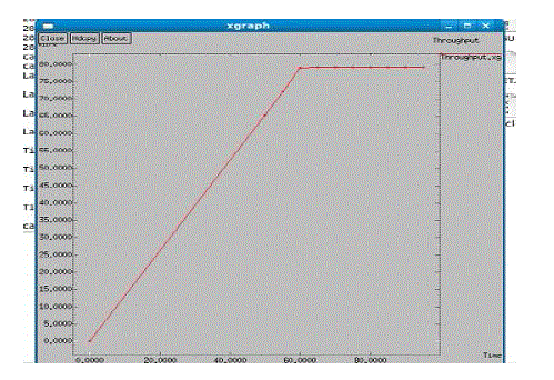
| Here the vehicular Adhoc network implemented with roadside infrastructure has been taken and the graph was successfully transmitted packets (Throughput). |
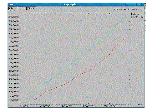
| Figure 4.1 shows the average rate of packet delivery of efficient data dissemination in vehicular Adhoc network. This result shows that Can DELIVER achieves 80-85 % good throughput. |
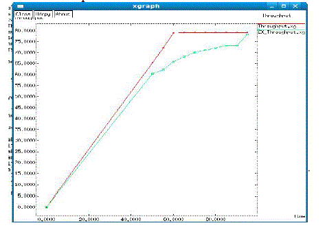
| It is shown in the Figure 4.2, delay analysis is made between the CAN DELIVER and SADV routing. This proves that sending packets through the RSU network reduces overall delay for far distances. This graph for average delay in transmission of packets versus number of vehicles is plotted. |
| In Figure 4.3 throughput analysis is made between the CAN DELIVER and CMP routing. This result shows that CMP achieves 85-90% good throughput. This graph for throughput in transmission of packets versus number of RSUs is plotted. |
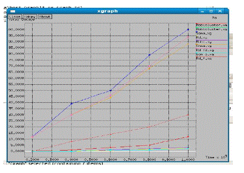
| It is shown in the Figure 4.4, throughput analysis is made between the Uniform placement,Hot Spot placement and CMP routing. This proves that CMP achieves 100% throughput. |
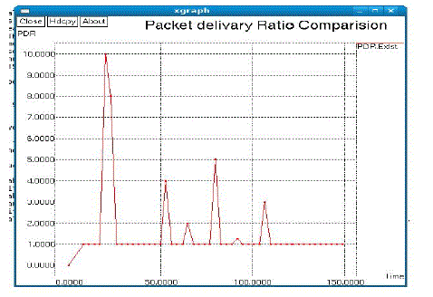
| In figure 4.5 representing the packet delivery ratio of Capacity Maximization Placement is high that the graph plotted for deliver packets (delivery ratio) versus transmission time. This shows that sending packets through RSU network improves the general delivery ratio. |
| This show that throughput analysis is made between the Uniform placement,Hot Spot placement and CMP routingand CAN DELIVER Apporoach. This proves that CMP achieves 100% throughput. |
CONCLUSION
|
| In this proposed a Capacity Maximization Placement (CMP) scheme which adapts to different vehicle population distribution and different vehicle speeds on the road. Specifically, when the vehicle population distribution exhibits more fluctuations, the set of RSUs is spaced apart more uniformly on the road; when there are only a few dense areas on the road, RSUs tend to be placed near these hotspots. Moreover, in a dense area, the relative speed among vehicles is smaller so that the link is more robust due to longer link lifetime. Therefore, proposed scheme prefers multi-hop relaying for vehicles so as to better utilize wireless resource. On the other hand, in a sparse area, the relative speed is more variable, thereby the link may be more error prone and unpredictable. The results show that our strategy leads to the best performance as compared with the uniformly distributed placement and the hot spot placement. This proposed system achieves 85-90% good throughput and sending packets through RSU network improves the general delivery ratio. This proves that sending packets through the RSU network reduces overall delay for far distances.More importantly, proposed solution needs the least number of RSUs to achieve the maximal aggregate throughput in the network, indicating that proposed scheme is indeed a cost effective yet highly efficient placement strategy for vehicular networks. |
| |
Tables at a glance
|
 |
 |
| Table 2.1 |
Table 4.1 |
|
| |
Figures at a glance
|
 |
 |
 |
 |
| Figure 1.1 |
Figure 2.1 |
Figure 3.1 |
Figure 4.1 |
| |
 |
 |
 |
 |
| Figure 4.2 |
Figure 4.3 |
Figure 4.4 |
Figure 4.5 |
|
| |
References
|
- Ahlswede .R, Cai.N, Li.S, and Yeung.R(2012), “Networkinformation flow,” IEEE Trans. Inf. Theory, vol. 46, no. 4, pp.1204–1216.
- AtefAbdrabou and WeihuaZhuang(2012),”Probabilistic delay control and road side unit placementfor vehicular adhoc networks with disruptedconnectivity”, IEEE. vol.29, no. 1, pp. 129-139.
- Aslam .B, Wang. P, and Zou .C (2011), “Aneconomical, deployable and secure vehicular ad hocnetwork,” in Proc. MILCOM, San Diego, CA , pp.1–7.
- Bae .Y and VaidyaN.H , “Location-aided routing(LAR) in mobile ad hoc networks,” in Proc. MobiCom,Dallas, TX, pp. 66–75.
- Casteigts .A, Nayak .A, and Stojmenovic.I,“Communication protocols for vehicular vehicularadhocnetworks,” Wirel. Commun. Mobile Comput., vol. 11, no. 5,Pp.567– 582.
- Chung-Ju Chang, Tsung-Jung Wu and Wanjiun Liao(August 2012) ,” A cost-effective strategy for road-sideunit placement in vehicular networks”, IEEE Trans. Comm,vol. 60, no. 8, pp. 2295-2303.
- Daniel Baselt, Florian Knorr, Martin Mauve, andMichael Schreckenberg , (October 2012), ” ReducingTraffic Jams via VANETs”, IEEE Trans. Vehicular Tech,vol. 61, no.8, pp. 3490- 3498.
- Ding .Y, Wang .C, and Xiao.L (Sep. 2007), “A staticnodeassisted adaptive routing protocol in vehicularnetworks ,” in Proc. VANET, pp. 59–68.
- Frank .R, Giordano .E, and Gerla .M, “TrafRoute:A different approach to routing in vehicularnetworks,” in Proc. VECON, pp. 521–528.
- Freudiger .J, Manshaei .M, HubauxJ.-P., and Parkes.D, “On non cooperative location privacy: A gametheoreticanalysis,” in Proc. CCS, pp. 324–337.
- Hassan Artail, KhaleelMershad, and MarioGerla (2012), ” We can deliver messages to farvehicles”, IEEE Trans.. Intelligent Trans. Pp 1-17.
- Ko .Y, Sim .M, and Nekovee .M, “ Wi-Fi basedbroadband wireless access for Users on the road, ” BTTechnol. J., vol. 24, no. 2, pp. 123–129.
- Leontiadis . I., Marfia. G, Mack.D, Pau G.,Mascolo. C, and Gerla .M, “On the effectiveness of anopportunistic traffic management system for vehicular networks,” IEEE Trans. Intell. Transp. Syst., vol. 12, no. 4pp.1537–1548.
- Li .L and Sun .L, “Seer: Trend- prediction-basedgeographic messages forwarding in sparse vehicularnetworks,” in Proc. ICC, pp. 1–5.
- Mehdi Khabazian, Mustafa Mehmet- Ali andSonia Aïssa (2012), “Performance Modeling of SafetyMessages Broadcast in Vehicular Ad Hoc Networks”, IEEETrans. Pp. 1-8.
|