Keywords
|
| Dual-band Antenna, Folded Slot Antenna, GALILEO, GLONASS, GNSS, GPS, Slotted Antenna. |
INTRODUCTION
|
| With the deployment of several GNSS such as GPS, GLONASS and GALILEO, and with the growing need to develop systems capable of receiving signals from any GNSS, it is necessary to design a compact antenna operating in all frequency bands for at least the three major systems: GPS, GALILEO and GLONASS. |
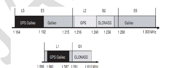
| As shown in Fig1, the GPS satellites transmit signals using three different bands centred on the frequencies: |
| L1: 1 575.42 MHz , L2: 1 227,60 MHz, L5: 1 176,45 MHz. |
| The GALILEO satellites transmit signals using three different bands centred on the frequencies: |
| L1: 1 575.42 MHz , E6: 1 278.75 MHz , E5: 1 191.79 MHz |
| And the GLONASS satellites transmit signals using two different bands centred on the frequencies: |
| G1: 1 248 MHz, G2: 1 600 MHz [1]-[3]. |
| One of the ways to design a broadband and multiband antenna is to set-up slots on the radiation elements [4], [5]. |
| In this paper, a novel dual-band rectangular CPW folded slot antenna is presented. This antenna is designed for operating in all the bands of the three GNSS Systems GPS, GALILEO and GLONASS. Also the antenna is simulated by “FEKO 6.3” [6], manufactured and measured by “Feedback Antenna Lab 52-200”. |
LITEARTURE SURVEY
|
| With the proliferation and miniaturization of telecommunications systems and their integration in restricted environments, such as Smart-phones, tablets, cars, airplanes, and other embedded systems. The design of compact multi-bands and Ultra Wide Band (UWB) antennas becomes a necessity. For designing this kind of antennas, several techniques are used such as using fractal geometries or adding slots to the radiating elements [7]-[10]. |
ANTENNA GEOMETRY
|
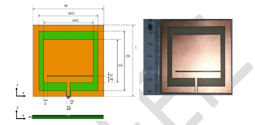
| The geometry of the proposed antenna is shown in fig2. The antenna is printed on a FR4 dielectric substrate of relative permittivity εr = 4.3, thickness H=1.6mm, loss tangent = 0.025 and fed by a 50 Ω CPW transmission line with a signal strip width Wf and a gap distance G between the signal strip and the ground plane. Several studies have used this mode of feeding because it’s one of the techniques to increase the Bandwidth of the antenna [10]-[14]. |
| The parameters of the antenna are: W=60mm, Ws1=50mm, Ws2=42mm, L=60mm, Ls1=50mm, Ls2=36mm, G=0.5mm, Wf=1.5mm, D=3mm, L1=1mm and H=1.6mm. |
DESIGN OF THE ANTENNA
|
A. The patch antenna
|
| It is very important for the simulation by FEKO to estimate the resonant frequency to have an idea about the dimensions of the patch antenna. |
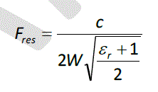
| Based on the TLM (Transmission Line Model), the resonant frequency (Fres) of the patch antenna is approximated by the equation (1)[15] |
 (1) (1) |
| With: c = 3.108ms-1 |
| εr: the relative permittivity of the dielectric |
| W: the width of the patch |
| For example, if fres=2.2GHz and εr = 4.3, the width of the patch is 42mm. |
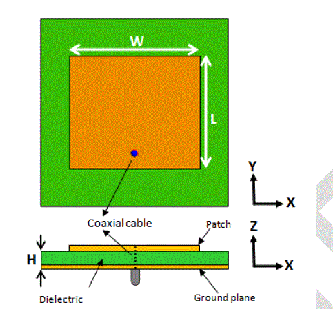
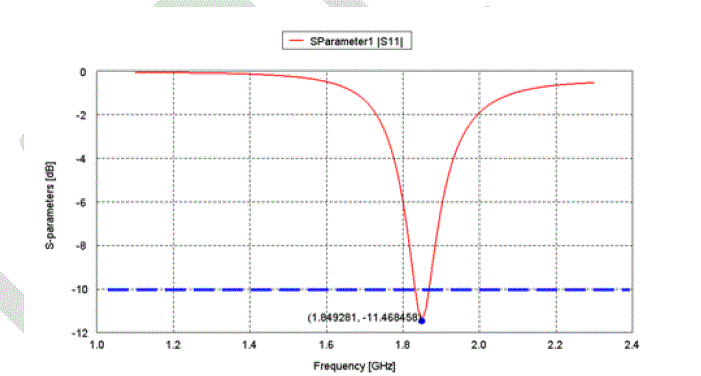
| Using the FEKO software to design a patch antenna with the following parameters: W=42mm, L=36mm, and H=1.6mm (Fig.3) The S11 characteristic of the simulated structure is depicted in Fig4. From the results, it is evident that the antenna operates at the frequency 1849MHz whose S11= -11.46dB with a bandwidth (-10 dB) of 38 MHz. We observe that this value is different for the resonant frequency given by the TLM model because the FEKO software is based on a full wave method: the Method of the Moment (MoM). The full wave methods like the MoM, the Finite Integral Technique (FIT), and Finite Element Method (FEM) are more accurate compared to the TLM method[7] [12] |
B. Feeding methods of the patch antenna
|
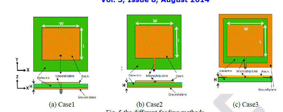
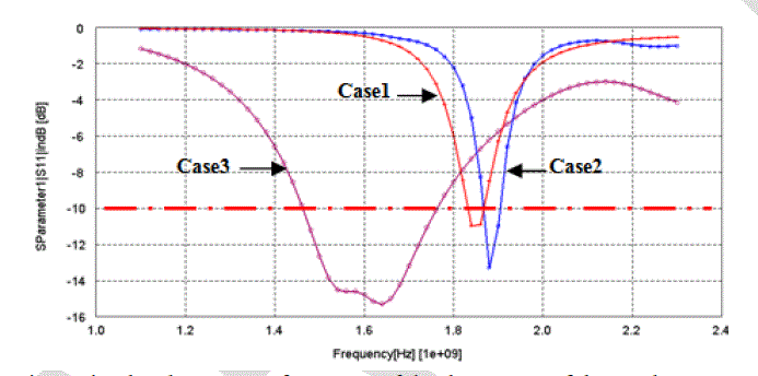
| There are many configurations that can be used to feed a patch antenna. In this section we compare the effect of three feeding methods: coaxial probe (Fig.5 - case1), Microstrip line with the ground plane in the reverse face of the patch (Fig.5 – case2), and Microstrip line with the ground plane in the same face of the patch (Fig.5 – case3). |
| We note that for the case 3 (Fig.6) the resonant frequency is lower than for the case 1 and 2. This is an important advantage to design a miniaturized antenna without increasing its volume and surface. We note also that the bandwidth is larger than those of case 1 and case 2. |
C. The choice of H1
|
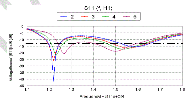
| To generate multi-resonance antenna, we setup a slot on the patch antenna as shown in fig.2. The H1 parameter is the position of this slot. |
| We will vary the H1 parameter from 2 to 5mm with step of 1mm. we obtain the result shown in (Fig.7). We can consider that the H1=2mm is the most appropriate for the GNSS applications; the table1 shows the detail of the result. |
| We note that for H1=2mm and H1=3mm the antenna operates for all the bands of all the GNSS Systems. |
RESULTS AND DISCUSSION
|
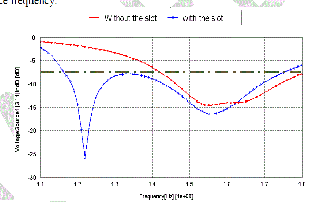
| First we simulated the patch antenna with and without the slot. The figure (Fig8) shows that the set up of the slot provides a new resonance frequency. |
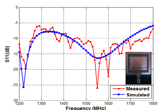
| After that, we manufactured the antenna on a PCB (Printed Circuit Board) and we measured the S11 of the slotted patch antenna with the Feedback Antenna Lab 57-200, which can measure the S11 parameter in the band of 1200-1800MHz. We note that the measured and simulated S11 of the antenna are nearly the same, even if we observe that there is a small instability in the measured S11 due to the measurement environment (fig9). |
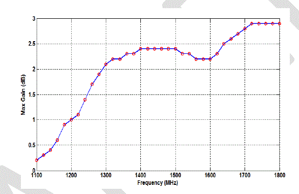
| Also, the simulated maximum total gain of the antenna varies between 0.2dB and 2.9dB in the band of 1200-1800MHz (Fig10). |
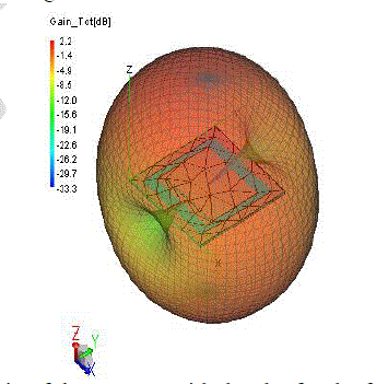
| We observe also that the simulated 3D total gain of the antenna is bi-directional (Fig11) |
CONCLUSION
|
| A dual-band rectangular CPW folded slot antenna is simulated with “FEKO 6.3” and measured by “FeedBack Antenna Lab 52-200”. |
| The antenna operates for all the bands of the GNSS Systems (L1-L2-L5-E5-E6-G1-G2) and its maximum gain varies between 0.2dB and 2.9dB in the band of 1200-1800MHz. |
| Also, further refinement can be done to improve the gain and to miniaturize the antenna. |
| |
Tables at a glance
|
 |
| Table 1 |
|
| |
Figures at a glance
|
 |
 |
 |
 |
 |
| Figure 1 |
Figure 2 |
Figure 3 |
Figure 4 |
Figure 5 |
| |
 |
 |
 |
 |
 |
| Figure 6 |
Figure 7 |
Figure 8 |
Figure 9 |
Figure 10 |
| |
 |
| Figure 11 |
|
| |
References
|
- P.MisraandP.Enge, Global Positioning System: Signals, Measurements, and Performance. Lincoln, MA, USA: Ganga-Jamuna Press, 2010.
- N. Samama, Global Positioning: Technologies and Performance. New York, NY, USA: Wiley, 2008.
- Jean-Marc Piéplu, GPS et Galileo: Systèmes de positionnement par satellites, Eyrolles, ISBN : 978-2-212-11947-3, 2006
- FEKO 6.3 User’s Manual,” EM Software & Systems-S. A, October 2013, pp.1-1.
- Ahmad A. Gheethan and Dimitris E. Anagnstou, "Broadband and Dual-Band Coplanar Folded-Slot Antennas (CFSAs) " IEEE Antennas andPropagation Magazine, Vol. 53, No.1, pp 80-89, February 2011.
- Long Zheng, and Guangming Wang, "DESIGN OF TRIPLE-FREQUENCY FOLDED SLOT ANTENNA FOR 2.4/3.5/5.2/5.8-GHz WLANAPPLICATIONS", Progress In Electromagnetics Research Letters, Vol. 43, pp115-123, 2013
- K. F. Lee, S. L. S. Yang, and A. A. Kishk, “Dual- and multiband U-slotpatch antennas,” IEEE Antennas Wireless Propag. Lett., vol. 7, pp. 645–647, 2008.
- C. Hsieh, T. Chiu, and C. Lai, “Compact dual-band slot antenna at the corner of the ground plane,” IEEE Trans. Antennas Propag., vol. 57, no.10, pt. 2, pp. 3423–3426, Oct. 2009.
- PengGao, Shuang He, Xubo Wei, Ziqiang Xu, Ning Wang, and Yi Zheng , “Compact Printed UWB Diversity Slot Antenna With 5.5 –GHz Band-Notched Characteristics”, IEEE Antennas and Wireless Propagation Letters, Vol. 13, 2014, pp 376-379
- A. Reha and A. Oulad Said, "Tri-Band Fractal Antennas for RFID Applications," Wireless Engineering and Technology, Vol. 4 No. 4, 2013,pp. 171-176. doi: 10.4236/wet.2013.44025.
- A. Mak, C. R. Rowell, R. D. Murch, and M. Chi-Lun, “Compact multiband planar antenna for 2.4/3.5/5.2/5.8-GHz wireless applications,” IEEEAntennas Wireless Propag. Lett., vol. 11, pp. 144–147, 2012.
- D. C. Chang, B. H. Zeng, and J. Liu, “CPW-fed circular fractal slot antenna design for dual-band applications,” IEEE Trans. Antennas Propag.,vol. 56, no. 12, pp. 3630–3637, Dec. 2008.
- Bala, B.D. ; Rahim, M.K.A. ; Murad, N.A. ; Ismail, M.F. ;Majid, H.A. , Design and Analysis of Metamaterial Antenna Using TriangularResonator, Microwave Conference Proceedings (APMC), 2012 Asia-Pacific
- Ming Chen, Chi-Chih Chen, A Compact Dual-Band GPS Antenna Design, IEEE ANTENNAS AND WIRELESS PROPAGATION LETTERS,pages 245-248, VOL. 12, 2013
- Constantine A. Balanis, Antenna Theory - Analysis and Design, A JOHN WILEY & SONS, INC. PUBLICATION, 2005.
|