Keywords
|
| Near-Field Antenna Measurement, Inverted quad-ridge horn antenna, Wideband Antennas, Dual Polarized Antennas, Ansoft HFSS. |
INTRODUCTION
|
| Microwave communication deals with systems that both radiate and receive electromagnetic energy. Each of these systems requires some type of antenna to grab the energy. Antennas are the fundamental component of modern communication systems. A large variety of antennas are developed to date, they range from simple structures such as monopoles and dipoles to complex structures such as phased arrays. The particular type of antenna selected for a certain purpose depends on the system requirements.Antenna measurement is also a major field of concern. Currently, different testing methods correlate to two different regions used to measure antennas. The far-field region, also referred to as the Radiating Far-Field or the Fraunhoffer Zone, is defined as the zone where the electromagnetic wave pattern does not change with distance [1]. Antenna manufacturers only undertake the more costly and resource demanding farfield test infrequently. Although there is not a strict definition of the far-field, one common approximation for electrically large antennas mathematically represents this area as d ≥ 2D2/λ, where d is the distance from the antenna to the sensor, D the largest dimension of the antenna, and λ the wavelength. Another common approximation which makes no mention of the antenna size is that d>10λ [1]. |
| Usually antenna measurements are done in far-field range. Far-field measurements have several disadvantages which include problems due to weather, electromagnetic interference, security concerns, etc. The antenna developers use anechoic chambers where the range length r > 2D2/λ, which in many cases dictates large distances. Thus to meet the distance anechoic chamber distance should be increased which is uneconomical. Horn antenna was selected due to its ease of construction and wideband performance. Introducing ridges into the horn widens the bandwidth usage as well as provide smooth impedance transfer from guide impedance 50 ohms to free-space impedance 377 ohms. An inverted quad-ridged horn antenna was chosen because of its inherent robustness, wide bandwidth, high gain, high directivity performance and high peak power handling capacity. Specifically the band considered is 1-18 GHz. The next step is designing the antenna with accurate dimensions so that it would meet the aforementioned characteristics. Therefore it is necessary to use simulation programs to test performance of the antenna before fabrication. In order to calculate the full three-dimensional electromagnetic field inside a structure and the corresponding S-parameters, High Frequency Structure Simulator (HFSS) software is used. This paper analyzes the performance of an inverted quad-ridge horn antenna to be used as a probe for near-field antenna measurements. |
LITERATURE SURVEY
|
| [1] Simulation study of a 4-28 GHz double ridged conical horn antenna The work is done on a double ridged horn antenna which is conical in shape. The designed horn offers a VSWR of less than 1.6 over its entire frequency bandwidth. The geometry as well as design of ridges is presented here. CST Microwave Studio is the software used. |
| [2] A Comparison of Double-Ridged and Quad-Ridged Hom Antenna for Microwave Tumor detection The authors Hana Amjadi, Mohammed Ismail presents a study of high-resolution and high-contrast microwave imaging in early breast tumors detection. |
| [3] Design and measurement techniques for Circularly polarized , dual fed, High Gain, Light weight, Wideband Conical Horn Antenna with Suppressed Sidelobes and High performance radome for space applications. |
| The paper discusses the design and measurement techniques of a circularly polarized, high gain conical horn antenna for space application. |
| [4] A new 2-18 Ghz Quad-Ridged Horn antenna |
| New designs of an wideband (2–18 GHz) quad-ridged pyramidal horn antenna is presented by Dubrovka And S. I. Piltyay. In the operating frequency range VSWR doesn't exceed 1.8.The work explains about a quad-ridged horn antenna. The antenna is dual-polarized. The paper explains that when broadband or ultra wideband horns are required, ridges in the waveguide transition portion as well as in the flare section are required. Inserting ridges in the E/H plane of a waveguide lowers the lowest cut-off frequency and at the same time increases the cut-off frequency of the next higher mode. The process has been done on a pyramidal horn antenna. |
| [5] Design of Waveguide Fed Broadband Circular Polarization Truncated Horn Antenna for High Power Applications |
| In this paper, Theng Huat Gan and Eng Leong Tan have described the design of a waveguide fed broadband CP truncated horn antenna for high power applications. It consists of a CP truncated horn antenna and a truncated-square to rectangular waveguide transition. CP modes were obtained by truncating the corners of the horn. |
| [6] Measuring accurate low cross polarization using broad band, dual polarized probes |
| It has been shown here that broad band probes with relatively low axial ratios can be calibrated for better performance. The paper describes about measurement of low cross polarization which can be used as near-field probe. The author’s Patrick Pelland and Allen Newell compares open ended waveguide to linear polarized probes and concludes that OEWG need not be calibrated but linear polarized probes are to be calibrated. |
| [7] Spherical near field testing of small antennas from 800mhz to 18ghz |
| This paper has evolved to cover the entire frequency band from 800MHz to 18GHz. The new system offers wider bandwidth, the speed advantages of a probe array while the mechanical rotation allows for unlimited angular resolution over the full sphere. L. J. Foged, J. Estrada, and P. O. Iversen have discussed about the measurement accuracies by comparison with reference data which helps to get an idea on the performance characteristics of such antennas. |
| [8] Wideband scalable probe for spherical near-field antenna measurements |
| The authors Oleksiy S. Kim, Sergey Pivnenko, and Olav Breinbjerg presents a design of an open-boundary quadridged horn to be used as a wideband scalable dual-linearly polarized probe for spherical near-field antenna measurements. The return loss, VSWR measurement and radiation pattern measurements is discussed here. |
HORN ANTENNA
|
| A. Structure of a Horn Antenna |
| Horns are the most widely used microwave antennas for measurement applications. Horn antennas are used in radio frequency applications above 300 MHz [2]. This type of antennas consists of a flaring metal waveguide shaped like a horn to direct radio waves in a beam. They are mostly used as feeders for standard calibration to measure other antenna’s gains, and as directive antennas for radar guns, automatic door openers and microwave radiometers. They have low SWR broad bandwidth and simple construction and adjustments. |
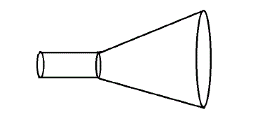
| A horn antenna generally represented as in Figure 1 is used to guide radio frequency microwave signals in a particular direction by controlling the direction of waves so that they can cover a greater distance with more accuracy. A simple horn antenna structure is shown in fig.1. Normally for near field antenna measurements open ended waveguides are used. The disadvantage of these open ended waveguide is that they have lower gain[3]. For more gain, a larger aperture is desirable but a longer waveguide is not. So if the waveguide size is slowly expanded or tapered into a larger aperture we get a horn thus increasing the impedance matching and thus provide a better gain performance [4]. |
DESIGN
|
| The design considerations of the probe antenna are discussed below. The project specifications are as follows. |
| • Type of antenna Dual polarized probe |
| • Frequency BW 1-18GHz |
| • Return loss < -10 dB |
| • VSWR < 2:1 |
| • Polarization Dual Linear H & V |
| • Antenna gain 7 dBi |
| • Impedance 50 Ohm |
B. Design of circular ridged waveguide
|
| Circular waveguides offer implementation advantages over rectangular waveguide in that installation is much simpler when forming runs for turns and offsets - particularly when large radii are involved - and the wind loading is less on a round cross-section, meaning towers do not need to be as robust. Manufacturing is generally simpler, too, since only one dimension - the radius - needs to be maintained [5]. |
C. Design of conical horn
|
| Simulations were used to tweak the device, but the baseline geometry for the conical horn was found using formulas. |
D. Quad ridged structure
|
| Ridged horn antennas are formed by loading the ridges centrally inside the horn antennas. The primary function of the ridges is to widen the operating bandwidth of the original horn. By virtue of this property, ridged horns are useful in wideband applications such as EMC/EMI measurements, medical imaging and electronic warfare applications. The ridged conical horn is considered since it has better performance and is easy to construct rather than any other horns. In light of this, the design of a conical ridged horn antenna is considered in this work [7]. |
| One advantage of quad-ridged horn antenna is the ability to transmit and receive dual linear polarization. The Figure 6 reveal that in the case of quad ridged horn, it is the aperture area with uniform phase that is shrinking as frequency is increased. This is obtained predominantly using ridge profile. Since the proposed antenna is dual polarized, instead of circular is replaced by a ridged waveguide [8]. |
SIMULATION RESULTS
|
| The HFSS model of the ridged waveguide structure is given in the below Figure 6. The dimensions of the horn antenna have been adjusted to be conveniently operating at 9.5 GHz centre frequency. The simulation uses the antenna solver. The dimensions of the antenna are as follows: |
| Length of the antenna (l) =130 mm |
| Diameter of circular waveguide section (d) =30 mm |
| Diameter of flared section (horn) =50 mm |
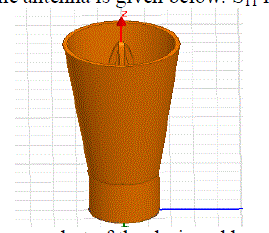
| Traditional dual polarized field probes are generally based on an Ortho Mode Junction (OMJ) with externally balanced feeding. The OMJ structure is completely symmetrical using two pairs of excitation pins, one pair for each polarization. The pins are feed from a pair of high precision 3dB, 0º / 180º hybrids in order to ensure the correct matching and to maximize the cross polar performance[8]. Since hybrid couplers do not satisfy wideband characteristics a ridged waveguide is designed. Ridges are inserted to provide wide bandwidth. A ridged waveguide was first designed to satisfy the specification. So first step was inserting ridges and iterating. As the ridges were inserted VSWR was not satisfied for the whole bandwidth. A screenshot of the inverted quad ridge horn antenna is shown in the figure 4. |
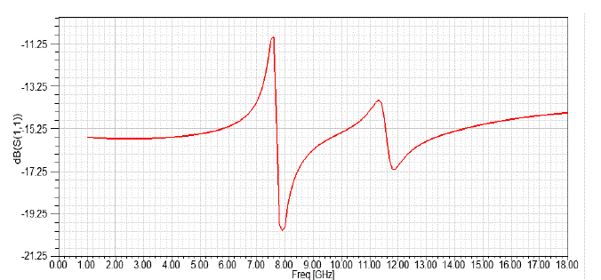
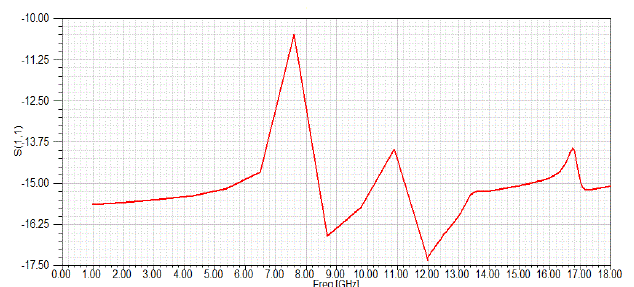
| The plot of reflection coefficient of the antenna is given below. S11 less than -10dB will be the desired value. |
| So the range of frequency below -10dB is of particular interest here. From the plot it is clear that the bandwidth of the antenna is 18GHz. |
E. VSWR for Horizontal Polarization
|
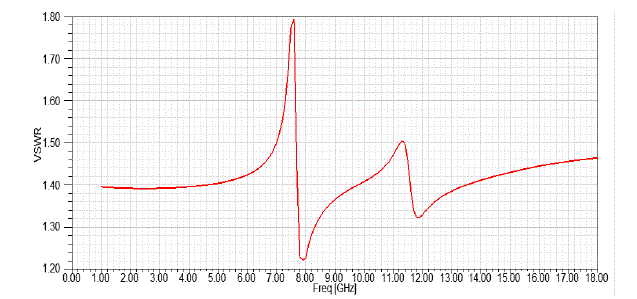
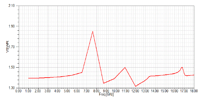
| The plot shown in fig.5 shows that VSWR specification is satisfied for the whole range of frequency and was found to be less than 1.8. Thus for horizontal polarization the antenna works in 1-18GHz frequency range. The maximum value of VSWR was found to be less than 1.9. |
F. Return loss for Horizontal Polarization
|
| The Return loss for horizontal polarization is plotted in fig.6. It was found to be within the specification. |
G. VSWR for vertical Polarization
|
| The retun loss was found to be less -10dB in fig.7 for vertical polarization. Thus the characteristics were met for particular specification. |
H. Return loss for vertical Polarization
|
| The maximum value of VSWR in fig.8 was found to be less than 1.9. The average VSWR was found to be 1.6295. |
I. Antenna Pattern
|
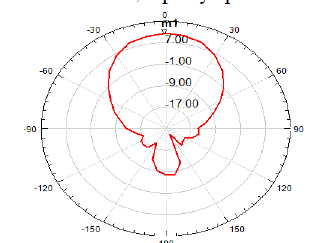
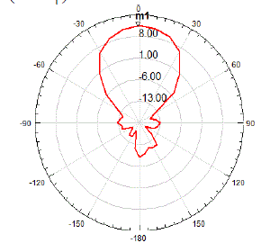
| A radiation pattern is a way of plotting the radiated energy from an antenna. This energy is measured at various angles at a constant distance from the antenna. In the polar-coordinate graph, points are located by projection along a rotating axis (radius) to an intersection with one of several concentric, equally-spaced circles. |
J. Beam Width
|
| The angular range of the antenna pattern in which at least half of the maximum power is still emitted is described as a Beam Width. Bordering points of this major lobe are therefore the points at which the field strength has fallen in the room around 3 dB regarding the maximum field strength. This angle is then described as beam width or aperture angle or half power (- 3 dB) angle - with notation Θ (also φ). |
| The beamwidth Θ is exactly the angle between the 2 red marked directions in the upper pictures. The angle Θ can be determined in the horizontal plane (with notation ΘAZ) as well as in the vertical plane (with notation ΘEL).The beam width is calculated as 600. |
K. Polar plot
|
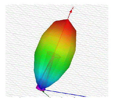
| The Figure below shows the 3D polar plot of the conical horn antenna. The energy distribution can be inferred from the polar plot. The red colour indicates the maximum field distribution. Horn antenna being a directive antenna has a major lobe directed from the flare opening. |
FABRICATION, MEASUREMENTS AND RESULTS
|
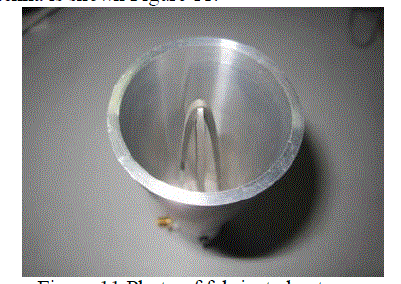
| The inverted quad ridged horn has been built in pieces. The conical part is build using lathe machine. The ridged part s are built using a numerically controlled milling machine. The ridges are bolted onto the sidewall. A coaxial cable is fed through one ridge with centre conductor connected to the opposite ridge. The coaxial line of the second polarization is physically above the first one. The inverted quad ridge horn antenna was machine fabricated using Aluminium of 3mm thickness. The photo of fabricated antenna is shown Figure 11. |
RESULTS AND DISCUSSION
|
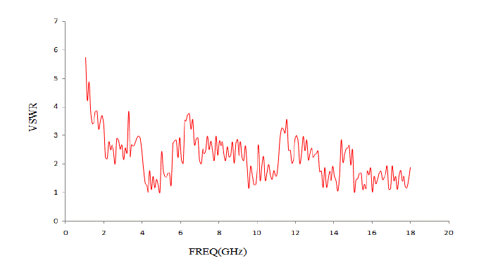
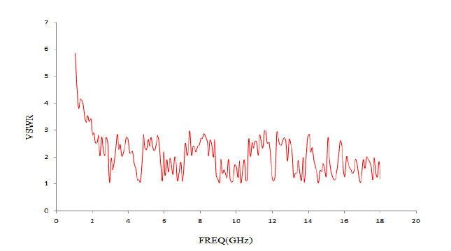
| Simulation results show that the antenna has a good performance for 1-18GHz. Thus wide bandwidth is satisfied during simulation. The VSWR and return loss criteria were also met. After fabrication the VSWR was measured values shows that the VSWR measured is less than 3 for the whole band of frequencies whereas the average VSWR for Vertical polarization is 2.5 and that of horizontal polarization is 2.2. |
| Even though there is a slight difference in measured and simulated values, a VSWR up to 2 was the specification but an antenna works good enough if the VSWR does not exceed 3:1. Thus the antenna is considered to work good for frequencies 1GHz and beyond thus providing a wide bandwidth. |
CONCLUSION
|
| After many years of development and independent industry evaluation, near-field antenna testing has come of age and is the preferred approach for characterizing antennas. Conventional far-field measurement ranges often are not adequate for testing such antennas accurately. Near-field measurement techniques have been developed to increase accuracy, throughput, lower costs, and provide antenna diagnostics. A near-field probe which is compact, having wider bandwidth and which causes fewer interactions to the AUT is to be designed. A horn antenna is considered an antenna whose bandwidth is wide and thus it is possible to measure antennas which have frequencies that fall in high frequency bands like L, S, C and X. A ridged waveguide offers measurement in wide range of frequencies. Inverting the ridges gives four symmetrical access point is obtained and thus dual polarization can be measured. This antenna is small in size thus reducing the coupling between the AUT and the probe. |
| |
Figures at a glance
|
 |
 |
 |
 |
 |
| Figure 1 |
Figure 2 |
Figure 3 |
Figure 4 |
Figure 5 |
| |
 |
 |
 |
 |
 |
| Figure 6 |
Figure 7 |
Figure 8 |
Figure 9 |
Figure 10 |
| |
 |
 |
| Figure 11 |
Figure 12 |
|
| |
References
|
- Near-field Measurement [online]Available:http://www. electronicinstrument.com/emmat
- L.J. Foged,A.Giacomini, “Wideband dual polarized probes for near-field Measurement”, IEEE Int. Symposium on Antennas andProp.2007,June,pp 10-15,USA
- Oleksiy S.Kim ,Sergey Pivnenko, and Olav Breinbjerg, ”Wideband Scalable Probe For Spherical Near-field Antenna Measurements",Proceedings of the 5th EUCAP, pp.1781-1785,2011
- Theng Huat Gan," Design of waveguide fed broadband circular polarization truncated horn antenna for high powerapplications",MicrowaveConference Proceedings (APMC),2011
- Chin Yeng Tan,Selvan K,"Simulation study of a 4-28GHz double ridged conical horn antenna",RF and Microwave conference,2008,IEEEInternational
- Richard C Johnson, Antenna Engineering handbook, second edition, McGraw-Hill Book Company ,1993
- Foged, L.J. Estrada, J, Iversen P.O, " Spherical near-field testing of small antennas from 800MHz to 18GHz",Antennas and PropagationSociety International Symposium,IEEE, 2007
- R. Dehdasht-Heydari, H. R. Hassani, and A. R. Mallahzadeh,"A new 2 to 18 Ghz quad-ridged horn antenna"Progress In Electromagnetics Research, PIER 81,pg: 183195, 2008
|