Keywords
|
| WCM, VGA Cable, Photo Darlington, LDR, LASER, etc. |
INTRODUCTION
|
| Setting up of a wireless connection between the CPU and the Monitor (screen).For designing purpose first Section study and understanding the computer Second section See the Challenged involved for setting connection between CPU and monitor Third section discuss Proposed method for CPU to Computer monitor. Section four discusses the future work for WCM. |
| Feasible for the CPU to computer monitor be kept far away from the rest of the components of the computer. Of course it is possible proposed method is discussed in this paper. WCM is available costing $750 in the US, feasible in a much lesser cost. |
RELATED WORKS OF WIRELESS COMPUTER MONITOR
|
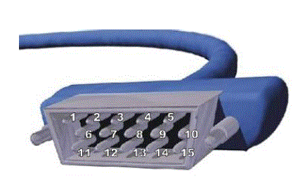
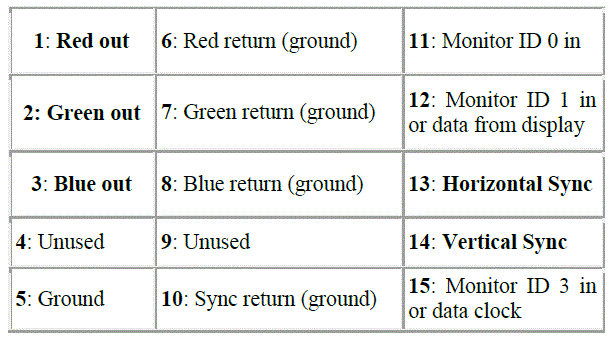
| Objective is setting up of a wireless connection between the CPU and the Monitor (screen). Computer monitor to CPU cable called Analog (VGA) because most monitors require the signal information in analog (continuous electrical signals or waves) form and not digital (pulses equivalent to the binary digits 0 and 1), they typically use an analog connection. Display information is in analog form, it is sent to the monitor through a VGA cable. The cable connects at the back of the computer to an analog connector (also known as a D-Sub connector) that has 15 pins in three rows VGA connector like this has three separate lines for the red, green and blue color signals, and two lines for horizontal and vertical sync signals. In a normal television, all of these signals are combined into a single composite video signal. |
CHALLENGES INVOLVED
|
| Challenging at the outset due to the heavy bandwidth consideration. i.e. 1024 (rows) *768(columns) *60 (refreshes per second) *32 (bit per pixel) = 184320 Kilo Bytes per Second = 180 Megabytes per second. |
| It is important that we maintain the great signal quality and the resolution, because the small distance between the eye and the monitor. This whopping amount of bandwidth may not be very easy to avail. |
| Now the available options for wireless communication between CPU and Monitor there are three proposed method for feasibility in this work. |
| A. IR transmission. |
| B. FM/ AM transmission. |
| C. Transmission though Optical medium. |
| A. IR TRANSMISSION/ DETECTION METHOD FOR WCM |
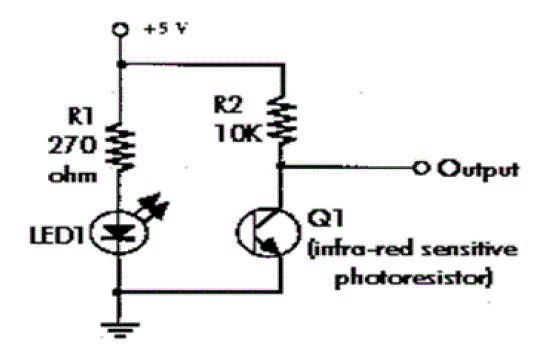
| Possible circuit uses of IR transmission use intensity modulation of an Infrared LED in the transmitter along with an Infrared-sensitive photo resistor as a detector IR Transmission would not be feasible due to the high bandwidth/ data-rate requirement, further they are limited in distance, due to divergent nature of the beam . |
| B. FM TRANSMISSION METHOD FOR WCM |
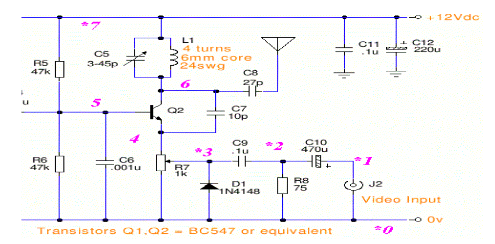
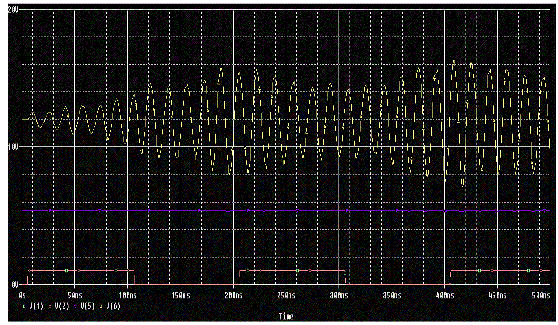
| In FM Transmission method uses a FM Transmission Circuit after PSpice coding of the FM transmission we see that output is not periodic, when the input is a periodic pulse and hence the demodulator or receiver circuit becomes too complicated. |
| Further for FM, the bandwidth available is not broad so, we had to abandon this idea as well as the idea of AM transmission, due to the above reasons. |
| C. TRANSMISSION THOUGH OPTICAL MEDIUM |
| Goal is to transmit 5 signals |
| 1. Red |
| 2. Green |
| 3. Blue |
| 4. Horizontal Sync. ( ≈ 67 KHz) |
| 5. Vertical Sync. (≈ 67 Hz.) |
| Now the Sync (Synchronization signals), methods used for multiple access for transmitting the various (5 required signals), in the optical communication domain uses a Spatial Division Multiple Access in this multiple access is a satellite communications mode that optimizes the use of radio spectrum and minimizes system cost by taking advantage of the directional properties of dish antennas These antennas are highly directional, allowing duplicate frequencies to be used for multiple surface zones. |
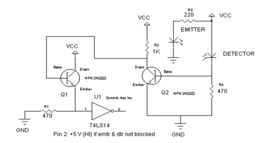
| SDMA is most convenient to implement, if we use laser torch, where light does not diverge to any appreciable extent. So we use a combination of LASER torch with an IR transmitter. Now we build a optical transmitter circuit and receiver circuit for Wireless computer monitor. |
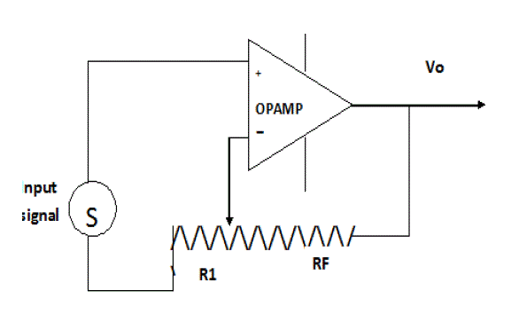
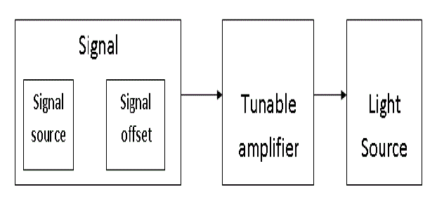
| In the Transmitter side we use a tunable amplifier, to give variable voltage, which would in turn modulate the intensity of the light source (LASER, LED etc.) |
OPTICAL RECEIVER CIRCUIT
|
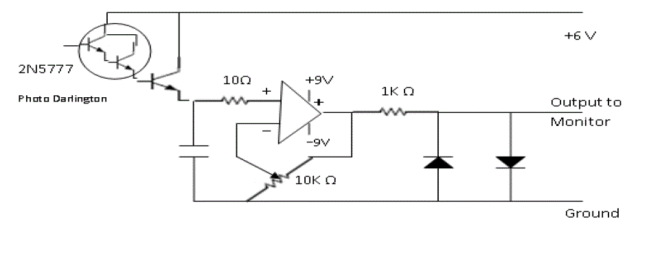
| In the Receiver side we use optical Receiver optical receiver consists of Photo Darlington (2N5777). It is an optical transducer which converts optical signal into electrical signal, when light is incident on photo Darlington it starts working i.e. the photo current flow in photo diode. There is very small current flow which is in mA, due to this small current a voltage is generated by the second transistor. After amplifying the voltage by use of a Darlington amplifier stage, we use low noise Operational Amplifier which amplifies the output voltage generated by transistor. Then we use a protection circuit, which consist of two diode connected in anti-parallel, to limit the voltage output to the monitor. |
FUTURE WORK
|
| In the Receiver the chief problem in this type of communication is the large scale „noiseâÃâ¬ÃŸ light e.g. sunlight etc. that is present here, there and everywhere. So once we remove this type of noise, we are ready with the cheapest transmitter/ receiver. We do this by getting a frequency selective receiver. But our path still had a lot of challenges and problems. These problems were like |
| 1. Interference with ambient light in case we use a Light Detecting Resistance (LDR). |
| 2. Over-heating in case of a LASER, destroys the functionality of a laser torch very soon. It does not allow a torch to be lit continuously for more than 3-4 minutes. |
| 3. Laser requires a minimum threshold voltage, so an offset is required to be supplied. |
CONCLUSION
|
| In this paper, we have got a daunting task of making possible a wireless communication from the Processor of a computer to the Monitor. We further found that worldwide research on the topic on these days, and the wireless monitor is not yet properly in the market (only some trial basis ones have been launched). Worldwide production of the Wireless Monitor as of now is mostly based on lowered resolution, serial communication. We have attempted to transfer the signals in a parallel communication method. We used light modulation, as it has the least Electromagnetic interference. Once the wireless monitor is launched, it will be an excellent utility for people who like to fix the bulky CPU, and carry the light LCD monitor to another room. Further it will help in demonstration classes, where a teacher might wish to broadcast to all other. |
Figures at a glance
|
 |
 |
 |
 |
 |
| Figure 1 |
Figure 2 |
Figure 3 |
Figure 4 |
Figure 5 |
| |
 |
 |
 |
 |
| Figure 6 |
Figure 7 |
Figure 8 |
Figure 9 |
|
References
|
- Zeyu Zheng, Jianping Wang, Jin Wang, “A Study of Network Throughput Gain in Optical-Wireless (FiWi) Networks Subject to Peer-to-PeerCommunications”, in Proc. IEEE ICC 2009.
- D. Kotz and K. Essien. Analysis of a Campus-wide Wireless Network. In Proc. the Eighth Annual International Conference on MobileComputing and Networking (MOBICOM 2002)
- Y-C Hu, A. Perrig and D. B. Johnson, “Ariadne: A secure On-Demand Routing Protocol for Ad Hoc Networks,” in Proceedings of MOBICOM2002.
- A. Sinha and A. Chandrakasan “Dynamic Power Management in Wireless Sensor Networks” in IEEE Design & Test of Computers, Vol. 18, No.2, March-April 2001.
- Paulson, Linda Dailey, “A New Wi-Fi for Peer-to-Peer Communications”, IEEE Computer Society, Vol. 41, Issue 6, June 2008, pp. 19-21.
- H. Zhou, Y. Wang, and Q. Wang. Measuring Internet Bottlenecks: Location, Capacity, and Available Bandwidth. Networking and MobileComputing, 3619/2005:1052–1062, 2005.
- T. Wood, P. Shenoy, K.K. Ramakrishnan, and J. Merwe, The Case for Enterprise-Ready Virtual Private Clouds. In HotCloud, 2009.
- K. Dozer, C. Gauger, J .Spath, and S. Bodamer, "Evaluation of Reservation Mechanisms for Optical Burst Switching," AEU International Journalof Electonics and Communications, vol. 55(1), pp. 2017- 2022, January 2001.
|